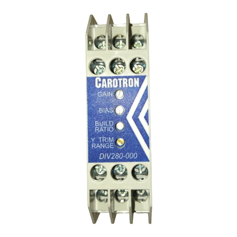
Carotron PI240-000 User manual

Proportional
Integral
Loop
Module
Instruction Manual
PI240-000

2
Table of Contents
1. General Description....................................................................................................... 3
2. Specifications ................................................................................................................ 3
2.1 Electrical ........................................................................................................... 3
2.2 Physical ............................................................................................................ 4
3. Installation ..................................................................................................................... 4
3.1 Wiring Guidelines ............................................................................................. 4
3.2 Signal Connections........................................................................................... 5
4. Description of Features & Adjustments ......................................................................... 6
5. Adjustment Procedure ................................................................................................... 7
5.1 Surface Follower Adjustment Procedure .......................................................... 8
5.2 Takeup (Winder) Adjustment Procedure ........................................................ 10
5.3 Letoff (Unwinder) Adjustment Procedure........................................................ 13
5.4 General PI Adjustment Procedure .................................................................. 16
6. Prints ........................................................................................................................... 17
C13702 PI240-000 Block Diagram .......................................................................17
C13701 PI240-000 Assembly ............................................................................... 18
C13703 PI240-000 General Connections.............................................................19
7. Standard Terms & Conditions of Sale .........................................................................21
List of Figures
Figure 1: Physical Dimensions .......................................................................................... 4
Figure 2: General Connections.......................................................................................... 5
Figure 3: Surface Follower Application Example ...............................................................8
Figure 4: Takeup (Winder) Application Examples ........................................................... 10
Figure 5: Letoff (Unwinder) Application Examples........................................................... 13

3
General Description
Model PI240-000 is designed for industrial applications that require a basic Proportional-
Integral (PI) loop controller. Some example applications include Dancer Positioning and
Loadcell Tension Control.
The PI module includes onboard multi-turn potentiometers for adjusting the Setpoint
(SP), Proportional Gain, Integral Time, and PI Trim. The module provides terminals for
connecting the process variable (PV or feedback) signal and an optional summing input
signal. Additional terminals also provide for an Enable and Teach inputs. Furthermore,
the Teach input can also be used to control the polarity (unipolar/bipolar) of the Integral
component. An internal jumper allows selection of a voltage or current output. Onboard
EEPROM is used to backup and retain the feedback calibration values during a power
loss.
Specifications
2.1 Electrical
D.C. Power Input
•24 VDC ±10%, 60mA max,
internally fused
+10VDC Reference Output
•10mA max
Feedback/Sum Inputs
•Range: 0-10VDC
•Input Impedance: 10
12
Ω
Potentiometers
•Turns: 15
Signal Output
•Voltage Output
Selected by position V on J2. This
circuit allows the output to source a
voltage level of up to +10 VDC into a
minimum resistance of 600 Ohms. If
resistance is too low, output linearity
may be affected.
•Current Output
Selected by position I on J2. This
circuit allows the output to source a
regulated current up to 20mA into a
maximum resistance of 500 Ohms.
Temperature Range
•0-55º
1
11
1
2
22
2

4
2.2 Physical
Figure 1: Physical Dimensions
Installation
3.1 Wiring Guidelines
To prevent electrical interference and to minimize start-up problems, adhere to the
following guidelines:
Use fully insulated and shielded cable for all signal wiring. The shield should be
connected to circuit common at one end only. The other end of the shield should be
clipped and insulated to prevent the possibility of accidental grounding.
Signal level wiring such as listed above should be routed separately from high level
power wiring (such as the A.C. line, motor, operator control, and relay control wiring).
When these two types of wire must cross, they should cross at right angles to each
other.
Any relay, contactor, starter, solenoid or other electro-mechanical device located in close
proximity to or on the same line supply as the PI240-000 should have a transient
suppression device such as an MOV or R-C snubber connected in parallel with its coil.
The suppressor should have short leads and be connected as close to the coil as
possible.
3
33
3

5
3.2 Signal Connections
Figure 2: General Connections

6
Description of Features & Adjustments
JUMPER J2
Selects the Output Mode between Voltage or Current. Position V on J2 selects the
Voltage Mode and the output is sourced from terminals 7 & 8. Position I on J2 selects
the Current Mode and the output is sourced on terminals 7 & 9.
PI ENABLE Input
This input is used to enable the PI loop. Typically, a dry contact is wired between
terminals 10 & 11. When the ENABLE contact is closed, the signal output on terminal 7
will be composed of the PI+Summing Input (terminal 5). Opening the contact will disable
the PI loop and only the Summing Input signal will be on the output.
SETPOINT Potentiometer
This adjustment is used to define the PI setpoint (SP). Range is from 0.00% (fully
counter-clockwise) to 100.00% (fully clockwise).
PROPORTIONAL GAIN (P GAIN) Potentiometer
Sets the amount of the loop output signal that is based on the error (Setpoint-Feedback).
Increasing the gain improves the loop response but can also increase overshoot and
cause instability if set too high. Range is from 0 (fully counter-clockwise) to 10 (fully
clockwise).
INTEGRAL TIME (I TIME) Potentiometer
The Integral Time adjustment eliminates steady-state error. Decreasing the integral time
improves loop response. However, setting it too low can cause oscillation. The
adjustment is in seconds and corresponds to the amount of time that the PI Output
signal would take to integrate from 0% to 100%. Range is from 0.010s (fully counter-
clockwise) to 60s (fully clockwise).
PI TRIM Potentiometer
This adjustment controls the amount of correction that the PI loop can provide. Range is
from 0% (fully counter-clockwise) to 100% (fully clockwise). 100% signal corresponds to
10V or 20mA depending upon jumper J2.
SUM Input
In many industrial applications, the PI output is only needed to provide a slight correction.
In these cases, there is often another signal that can provide the majority of the output.
The Sum Input provides a means to sum an external signal with the PI output. There is
no scaling for this input. Thus, whatever signal level is present on the Sum Input will also
be present on the output (terminal 7) in addition to the PI signal.
An example is where two material handling rolls (nip rolls/ S-Wraps) are separated by a
dancer. It is desired for the follower roll to match speed with the lead roll. A speed
signal from the lead drive can be connected to the Summing Input. This input signal will
be present on the output (terminal 7) that is connected as a reference to the follower
drive. The follower drive can now be calibrated to track the speed of the lead drive very
closely. The PI loop (using a dancer or a loadcell) then only needs to provide a very
small correction to this “Line Speed” summed signal so that the follower drive provides
the desired speed.
4
44
4

7
TEACH/BIPOLAR INPUT
Often, the process variable (PV, feedback) signal may not be a nominal 0 to 10VDC
signal due to mechanical limitations (especially on dancer feedback applications). The
Teach input can be used to calibrate the minimum and maximum voltage inputs levels.
Transitions on the Teach input (within one minute of applying power) cause the module
to learn the signal level currently applied to terminal 4. The order in which the minimum
and maximum signal levels are taught will affect the logic of the control loop. With
dancer systems, this would be the same as swapping the outer leads of the dancer
feedback potentiometer.
The Teach function must be initiated (not completed!) within one minute of power being
applied to the module. Initially start with the Teach input terminal disconnected and
apply power to the module. Apply either the minimum or maximum signal level (typically
minimum) to terminal 4. Teach this level by connecting the Teach input (terminal 12) to
circuit common (terminals 11). Next, apply the other extreme signal (typically the
maximum) to terminal 4. Teach this level by disconnecting the Teach input from circuit
common. If an error is made during the teach process, simply power down the module
and repeat the process above.
The Teach Input is also used to select the polarity of the integral component. In Unipolar
mode, the integral component is positive only and thus can only add to the Summing
signal. In Bipolar mode, the integral component can be positive or negative and can add
or subtract to the Summing Signal. Note that the unipolar/bipolar mode only reflects the
polarity of the integral component, not the polarity of the final output on terminal 7. The
final output (PI + Summing) on terminal 7 is a unipolar output only (i.e., it cannot go
negative).
After the one minute teach window has elapsed, the Teach input can be used to select
the polarity of the integral component. If terminal 12 is left unconnected, the INTEGRAL
component can only have a positive output (UNIPOLAR mode). If terminal 12 is
connected to common (terminal 11), the INTEGRAL component can have either a
positive or a negative polarity (BIPOLAR mode). If the Teach input is connected to
common when power is applied to the module, the teach function is bypassed and the PI
loop immediately enters the bipolar mode of operation.
Adjustment Procedure
WARNING! DURING CALIBRATION, THE PI240-000 MODULE WILL
PRODUCE AN OUTPUT. PLEASE DISCONNECT ANY EQUIPMENT
FROM THE MODULE THAT COULD BE DAMAGED OR CAUSE
INJURY DURING THIS PROCESS.
Proceed to Section 5.1, 5.2, 5.3 or 5.4 depending upon your application.
5
55
5

8
5.1 Surface Follower Adjustment Procedure
In a surface follower application, a Line Speed signal from the lead drive is connected to
the Summing Input on the PI module. This speed signal will pass through the module
and be present on the output, which is connected to the speed reference of the follower
drive. The follower drive’s surface speed should then be scaled to match the lead drive
as close a possible. A feedback device, such as a dancer or loadcell, can then be used
with the PI module to trim (slightly add or subtract) to the Line Speed signal to obtain the
desired speed and/or tension (Figure 3).
Step 1: Select Output Type
1. Select the type of output desired using Jumper J2. If a Voltage output is desired,
select V on J2 and use output terminals 7 (OUTPUT) and 8 (VOLTAGE
RETURN). If a Current output is desired, select I on J2 and use output terminals 7
(OUTPUT) and 9 (CURRENT RETURN).
Step 2: Connections
1. Make connections per drawing C13703 on page 19. Initially, there should be no
connection on the Teach input on terminal 12.
Step 3: Initial Setup
1. Initial commissioning should be performed without product in the machine.
2. Set Prop Gain potentiometer fully counter clockwise. Set all other potentiometers
to 8 turns clockwise. If the current positions are unknown or in doubt, rotate
potentiometer counter clockwise 20 turns, then clockwise 8 turns.
3. For dancer systems, verify that the full range of motion of the dancer does not
exceed the allowable electrical range (i.e., the potentiometer does not rollover
from min to max or vice versa).
Step 4: Teach Process Variable (Feedback)
1. The order in which the two extreme feedback levels (minimum and maximum) are
taught determines the logic of the control loop.
2. For Dancer systems, position the dancer at the extreme position that should force
the follower drive to increase in speed. For Loadcell systems, apply either no load
or full load (by hanging weights in the material path) to the loadcell that should
Figure 3: Surface Follower Application Example

9
cause the follower drive to increase in speed.
3. Apply power to the PI240-000 Module. Within one minute, connect the Teach
input (terminal 12) to circuit common (terminal 11).
4. For Dancer systems, position the dancer at the other extreme position that should
force the follower drive to decrease in speed. For Loadcell systems, apply the
other extreme signal (either no load of full load) that should cause the follower
drive to decrease in speed.
5. Disconnect the Teach input (terminal 12) from circuit common (terminal 11).
Step 5: Select Bipolar Integral
1
1. Wait at least one minute after applying power to the module and place a jumper
from the Teach input (terminal 12) to circuit common (terminal 11).
Step 6: Speed Match
1. Ensure the enable contact between terminals 10 & 11 is open.
2. Enable the lead and follower drives. Run the lead drive up to maximum desired
speed. The line speed reference signal that is connected to the Summing Input
on terminal 5 should be scaled to a maximum of approx. 8 volts (this allows an
additional 2 volts for the PI component).
3. Since any signal present on the Summing Input is also present on the output, the
follower drive should also be running. Using a handheld tachometer, adjust the
speed of the follower drive until its surface speed matches the lead drive. The
follower drive speed would typically be scaled by using its Max Speed or Analog
Input Gain adjustment.
Step 6: PI Trim
1. Manually force the dancer or loadcell feedback sensor so it is in the “speed up”
state.
2. Enable the PI loop by closing the contact across terminals 10 & 11. Verify that the
module output increases and causes the follower drive to increase in speed.
3. Likewise, manually force the dancer or loadcell feedback sensor so it is in the
“slow down” position and verify that the follower drive decreases in speed.
4. If the module exhibits opposite logic (i.e. increases speed when it should decrease
speed), then repeat Step 4 teaching the feedback levels in the opposite order.
5. With the feedback sensor in the “speed up” state, wait until the PI output saturates
(stops increasing) and adjust the PI Trim potentiometer until the follower drive
achieves the desired overspeed level (typically about 10%).
6. Stop all drives.
Step 7: Tune
1. Set Prop Gain potentiometer approx 8 turns clockwise.
2. Load material and run machine. For dancer systems, adjust the Setpoint
potentiometer to set the desired operating position of the dancer. For loadcell
systems, adjust the Setpoint potentiometer until the desired tension level is
achieved.
3. If necessary, adjust the Prop Gain and Integral Time potentiometers if any
instability is noticed or response time is sluggish.
1
NOTE! An alternate setup to the above would be to configure the PI module for unipolar operation. This
would then only allow the PI to add to the summed Line Speed signal. In this case, the follower drive speed
scaling performed in step 6 should be set slightly slower (5-10%) than the lead drive instead of a speed
match.

10
5.2 Takeup (Winder) Adjustment Procedure
In a takeup application, a Line Speed signal from the lead drive should be connected to
the Summing Input on the PI module. This speed signal will pass through the module
and be present on the output, which is connected to the speed reference of the takeup
drive. The takeup drive’s empty core surface speed should then be scaled to match the
lead drive as close a possible. A feedback device, such as a dancer or loadcell, can
then be used with the PI module to subtract from the Line Speed signal as the diameter
builds and slow the takeup drive down (Figure 4).
Step 1: Select Output Type
1. Select the type of output desired using Jumper J2. If a Voltage output is desired,
select V on J2 and use output terminals 7 (OUTPUT) and 8 (VOLTAGE
RETURN). If a Current output is desired, select I on J2 and use output terminals 7
(OUTPUT) and 9 (CURRENT RETURN).
Step 2: Connections
1. Make connections per drawing C13703 on page 19. Initially, there should be no
connection on the Teach input on terminal 12.
Step 3: Initial Setup
1. Initial commissioning should be performed with the smallest winder core that will
ever be used and without product in the machine.
2. Set Prop Gain potentiometer fully counter clockwise. Set all other potentiometers
to 8 turns clockwise. If the current positions are unknown or in doubt, rotate
potentiometer counter clockwise 20 turns, then clockwise 8 turns.
3. For dancer systems, verify that the full range of motion of the dancer does not
exceed the allowable electrical range (i.e., the potentiometer does not rollover
from min to max or vice versa).
Figure 4: Takeup (Winder) Application Examples

11
Step 4: Build Ratio
1. Determine the Build Ratio of the winder. If multiple sizes are used, calculate with
the smallest core diameter and largest maximum diameter. Note that the PI240-
000 module is only designed to handle build ratios of approximately 3 or less. For
larger Build Ratios, contact Carotron, Inc. for assistance.
lDiameter
MinimumRol
lDiameterMaximumRol
BuildRatio =
Step 5: Teach Process Variable (Feedback)
1. The order in which the two extreme feedback levels (minimum and maximum) are
taught determines the logic of the control loop.
2. For Dancer systems, position the dancer at the extreme position that should force
the follower drive to increase in speed. For Loadcell systems, apply either no load
or full load (by hanging weights in the material path) to the loadcell that should
cause the follower drive to increase in speed.
3. Apply power to the PI240-000 Module. Within one minute, connect the Teach
input (terminal 12) to circuit common (terminal 11).
4. For Dancer systems, position the dancer at the other extreme position that should
force the follower drive to decrease in speed. For Loadcell systems, apply the
other extreme signal (either no load of full load) that should cause the follower
drive to decrease in speed.
5. Disconnect the Teach input (terminal 12) from circuit common (terminal 11).
Step 6: Select Bipolar Integral
1. Wait at least one minute after applying power to the module and place a jumper
from the Teach input (terminal 12) to circuit common (terminal 11).
Step 7: Speed Match
1. Ensure the enable contact between terminals 10 & 11 is open.
2. Enable the lead and takeup drives. Run the lead drive up to maximum desired
speed. The line speed reference signal that is connected to the Summing Input
on terminal 5 should be scaled to a maximum of 9 volts.
3. Using a handheld tachometer, measure the surface speed of the lead drive. This
is the MaximumSurfaceSpeed. Adjust the (empty core) speed of the takeup drive
until its surface speed is slightly faster (10%) than this value. The takeup drive
speed would typically be adjusted by using its Max Speed or Analog Input Gain
adjustment.
Step 8: PI Trim
1. Manually force the dancer or loadcell feedback sensor so it is in the “slow down”
state.
2. Enable the PI loop by closing the contact across terminals 10 & 11. Verify that the
module output decreases and causes the takeup drive to decrease in speed.
3. Likewise, manually force the dancer or loadcell feedback sensor so it is in the
“speed up” state, and verify that the takeup drive increases in speed.
4. If the module exhibits opposite logic (i.e. increases speed when it should decrease
speed), then repeat Step 5 teaching the feedback levels in the opposite order.
5. With the dancer or loadcell in the “slow down” state, wait until the PI module
output on terminal 7 saturates (stops decreasing). Adjust the PI Trim

12
potentiometer until the takeup drive surface speed matches the
FinishSurfaceSpeed.
90.0×=
BuildRatio
faceSpeedMaximumSur
aceSpeedFinishSurf
For example, if the MaximumSurfaceSpeed (measured in step 7 above) is 300
Ft/Min, and the BuildRatio is 2.5, the FinishSurfaceSpeed is 108 Ft/Min.
6. Stop all drives.
Step 9: Tune
1. Set Prop Gain potentiometer approx 8 turns clockwise.
2. Load material and run machine. For dancer systems, adjust the Setpoint
potentiometer to set the desired operating position of the dancer. For loadcell
systems, adjust the Setpoint potentiometer until the desired tension level is
achieved.
3. If necessary, adjust the Prop Gain and Integral Time potentiometers if any
instability is noticed or response time is sluggish.

13
5.3 Letoff (Unwinder) Adjustment Procedure
In a letoff application, a Line Speed signal from the lead drive should be connected to the
Summing Input on the PI module. This speed signal will pass through the module and
be present on the output, which is connected to the speed reference of the letoff drive.
The letoff drive’s empty core surface speed should then be scaled to its max diameter
speed match. A feedback device, such as a dancer or loadcell, can then be used with
the PI module to add to the Line Speed signal as the diameter decreases and the letoff
speed increases (Figure 5).
Step 1:
Select Output Type
1. Select the type of output desired using Jumper J2. If a Voltage output is desired,
select V on J2 and use output terminals 7 (OUTPUT) and 8 (VOLTAGE
RETURN). If a Current output is desired, select I on J2 and use output terminals 7
(OUTPUT) and 9 (CURRENT RETURN).
Step 2: Connections
1. Make connections per drawing C13703 on page 19. Initially, there should be no
connection on the Teach input on terminal 12.
Step 3: Initial Setup
1. Initial commissioning should be performed with the smallest core that will ever be
used and without product in the machine. Load an empty core.
2. Set Prop Gain potentiometer fully counter clockwise. Set all other potentiometers
to 8 turns clockwise. If the current positions are unknown or in doubt, rotate
potentiometer counter clockwise 20 turns, then clockwise 8 turns.
3. For dancer systems, verify that the full range of motion of the dancer does not
exceed the allowable electrical range (i.e., the potentiometer does not rollover
from min to max or vice versa).
Figure 5: Letoff (Unwinder) Application Examples

14
Step 4: Build Ratio
1. Determine the Build Ratio of the letoff. If multiple sizes are used, calculate with
the smallest core diameter and largest maximum diameter. Note that the PI240-
000 module is only designed to handle Build Ratios of approximately 3 or less.
For larger Build Ratios, contact Carotron, Inc. for assistance.
lDiameter
MinimumRol
lDiameterMaximumRol
BuildRatio =
Step 5: Teach Process Variable (Feedback)
1. The order in which the two extreme feedback levels (minimum and maximum) are
taught determines the logic of the control loop.
2. For Dancer systems, position the dancer at the extreme position that should force
the follower drive to increase in speed. For Loadcell systems, apply either no load
or full load (by hanging weights in the material path) to the loadcell that should
cause the follower drive to increase in speed.
3. Apply power to the PI240-000 Module. Within one minute, connect the Teach
input (terminal 12) to circuit common (terminal 11).
4. For Dancer systems, position the dancer at the other extreme position that should
force the follower drive to decrease in speed. For Loadcell systems, apply the
other extreme signal (either no load of full load) that should cause the follower
drive to decrease in speed.
5. Disconnect the Teach input (terminal 12) from circuit common (terminal 11).
Step 6: Select Unipolar Integral
1. Ensure there is no jumper between terminals 11 and 12.
Step 7: Speed Match
1. Ensure the enable contact between terminals 10 & 11 is open.
2. Enable the lead and letoff drives. Run the lead drive up to maximum desired
speed. Using a handheld tachometer, measure the surface speed of the lead
drive. This is the MaximumSurfaceSpeed.
3. Divide 10V by the Build Ratio value to determine the maximum Summing Input
value. The line speed reference signal (from the lead drive) that is connected to
the Summing Input on terminal 5 should be scaled to slightly lower than this value.
For example, a Build Ratio of 2 would yield 10/2=5V. The Sum signal should then
be scaled approximately 10% lower to yield 4.5V.
4. Adjust the speed of the letoff drive until the empty core surface speed matches
the StartSurfaceSpeed.
90.0×=
BuildRatio
faceSpeedMaximumSur
ceSpeedStartSurfa
For example, if the MaximumSurfaceSpeed (measured above) is 350 Ft/Min, and
the BuildRatio is 2, the StartSurfaceSpeed is 158 Ft/Min. The letoff drive speed
would typically be adjusted by using its Max Speed or Analog Input Gain
adjustment.

15
Step 8: PI Trim
1. Manually force the dancer or loadcell feedback sensor so it is in the “speed up”
state.
2. Enable the PI loop by closing the contact across terminals 10 & 11. Verify that the
module output increases and causes the letoff drive to increase in speed.
3. Likewise, manually force the dancer or loadcell feedback sensor so it is in the
“slow down” state, and verify that the letoff drive decreases in speed.
4. If the module exhibits opposite logic (i.e. decreases speed when it should increase
speed), then repeat Step 5 teaching the feedback levels in the opposite order.
5. With the feedback sensor in the “speed up” state, wait until the PI output saturates
(stops increasing) and adjust the PI Trim potentiometer until the letoff drive
surface speed is approximately 10% faster than the MaximumSurfaceSpeed.
6. Stop all drives.
Step 9: Tune
1. Set Prop Gain potentiometer approx 8 turns clockwise.
2. Load material and run machine. For dancer systems, adjust the Setpoint
potentiometer to set the desired operating position of the dancer. For loadcell
systems, adjust the Setpoint potentiometer until the desired tension level is
achieved.
3. If necessary, adjust the Prop Gain and Integral Time potentiometers if any
instability is noticed or response time is sluggish.

16
5.4 General PI Adjustment Procedure
The following is a generic procedure for setting up the PI module.
Step 1: Select Output Type
1. Select the type of output desired using Jumper J2. If a Voltage output is desired,
select V on J2 and use output terminals 7 (OUTPUT) and 8 (VOLTAGE
RETURN). If a Current output is desired, select I on J2 and use output terminals 7
(OUTPUT) and 9 (CURRENT RETURN).
Step 2: Connections
1. Make connections per drawing C13703 on page 19. Initially, there should be no
connection on the Teach input on terminal 12.
Step 3: Initial Setup
1. Set Prop Gain potentiometer fully counter clockwise. Set all other potentiometers
to 8 turns clockwise. If the current positions are unknown or in doubt, rotate
potentiometer counter clockwise 20 turns, then clockwise 8 turns.
Step 4: Teach Process Variable (Feedback)
1. The order in which the two extreme feedback levels (minimum and maximum) are
taught determines the logic of the control loop.
2. Apply the feedback signal level (either minimum or maximum) to terminal 4 that
should cause the output to increase. Apply power to the module and within one
minute, connect the Teach input (terminal 12) to circuit common (terminal 11).
3. Apply the other extreme feedback signal level (either minimum or maximum) to
terminal 4 and disconnect the Teach input (terminal 12) from circuit common
(terminal 11).
Step 5: Select Unipolar or Bipolar
1. If bipolar operation is desired, wait at least one minute after the unit has been
powered and place a jumper from the Teach input (terminal 12) to circuit common
(terminal 11). No connection on terminal 12 selects unipolar.
Step 6: PI Trim
1. Manually force the feedback sensor so it is in the “increase output” state. Enable
the PI loop by closing the contact across terminals 10 & 11.
2. Verify that the module output signal increases.
3. Likewise, manually force the feedback sensor so it is in the “decrease output”
state and verify that the output decreases.
4. If the module exhibits opposite logic (i.e. increases speed when it should decrease
speed), then repeat Step 4 teaching the feedback levels in the opposite order.
5. Wait until the PI output saturates (stops increasing or decreasing) and adjust the
PI Trim potentiometer until the desired output level is achieved.
Step 7: Tune
1. Set Prop Gain potentiometer approx 8 turns clockwise.
2. Any signal applied to the Summing Input (terminal 5) will sum with the PI signal and
output on terminal 7.
3. If necessary, adjust the Prop Gain and Integral Time potentiometers if any
instability is noticed or response time is sluggish.

17
4.
Prints
6
66
6

18

19

20
Table of contents
Other Carotron Control Unit manuals
Popular Control Unit manuals by other brands

Burkert
Burkert 5411 operating instructions

TESY
TESY CN 06 100 EA CLOUD AS W quick start

Honeywell
Honeywell Hometronic HAV 20 Mounting and operation

Stenner Pumps
Stenner Pumps PCM series Installation and maintenance manual

Sharon Piping & Eqpt
Sharon Piping & Eqpt Sharpe Valves 53034 Installation, operation and maintenance instructions

Yoshitake
Yoshitake GD-24 Installation & operation manual