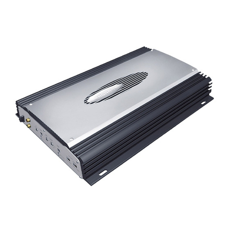
Carpower HPB-204 User manual

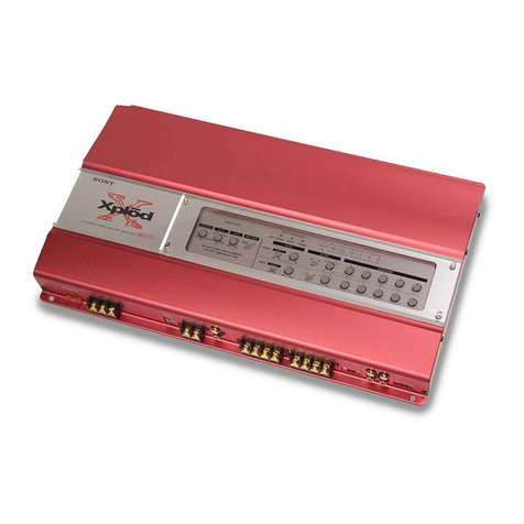
4-Kanal-Car-HiFi-Endstufe
4-Channel Car HiFi Power Amplifier
Amplificateur Hi-Fi Embarquée, 4 Canaux
Finale Di Potenza HiFi A 4 Canali Per Auto
HPB-204
Bestell-Nr. 14.2810
Montageanleitung • Mounting instructions
Notice d’utilisation • Istruzioni per il montaggio
Manual de instrucciones • Instrukcja montazowa
Veiligheidsvoorschriften • Sikkerhedsoplysninger
Säkerhetsföreskrifter • Turvallisuudesta

2
Vor der Montage ...
Wir wünschen Ihnen viel Spaß mit dem neuen
Gerät von CARPOWER. Bitte lesen Sie diese
Montageanleitung vor dem Betrieb gründlich
durch. Die Anleitung soll Ihnen eine schnelle und
einfache Montage ermöglichen. Hier finden Sie
dazu alle nötigen Informationen. Durch die Be-
achtung der Anleitung werden außerdem eventu-
elle Schäden am Gerät durch unsachgemäße
Montage vermieden. Heben Sie die Anleitung für
ein späteres Nachlesen auf.
Der deutsche Text beginnt auf der Seite 4.
Prior to Mounting ...
We wish you much pleasure with the new unit by
CARPOWER. Please read these operating
instructions carefully prior to operating the unit.
With these operating instructions a quick and
easy mounting will be possible. You will find all
necessary information here. By following these
instructions possible damage to the unit due to
improper mounting will be prevented. Please
keep the operating instructions for later use.
The English text starts on page 7.
Avant toute installation ...
Nous vous souhaitons beaucoup de plaisir à utili-
ser cet appareil CARPOWER. Lisez ce mode
dʼemploi entièrement avant toute utilisation. Cette
notice a pour objectif de faciliter le montage. Vous
y trouverez toutes les informations nécessaires.
En outre, en respectant les conseils donnés, vous
éviterez tout mauvais montage et donc dʼendom-
mager lʼappareil. Conservez la notice pour pou-
voir vous y reporter ultérieurement.
La version française se trouve page 10.
Prima del montaggio ...
Vi auguriamo buon divertimento con il vostro
nuovo apparecchio CARPOWER. Leggete atten-
tamente le istruzioni prima di mettere in funzione
lʼapparecchio. Le istruzioni che contengono tutte
le informazioni necessarie Vi permettono un mon-
taggio rapido e semplice. Rispettando quanto
spiegato nelle istruzioni evitate eventuali danni
allʼapparecchio in seguito ad un montaggio non a
regola dʼarte. Conservate le istruzioni per poterle
consultare anche in futuro.
Il testo italiano inizia a pagina 13.
D
A
CH
GB
Förskrift
Vi önskar dig mycket nöje med din nya enhet från
CARPOWER. Läs gärna säkerhetsinstruktio-
nerna innan du använder enheten. Genom att
följa säkerhetsinstruktionerna kan många pro-
blem undvikas, vilket annars kan skada enheten.
Spara instruktionerna för framtida användning.
Du finner säkerhetsinstruktionerna på sidan 24.
Ennen virran kytkemistä …
Toivomme, että uusi CARPOWER laitteesi tuo
sinulle paljon iloa ja hyötyä. Ole hyvä ja lue käyt-
töohjeet ennen laitteen käyttöönottoa. Luettuasi
käyttöohjeet voit käyttää laitetta turvallisesti ja
vältyt laitteen väärinkäytöltä. Ole hyvä ja säilytä
käyttöohjeet myöhempää tarvetta varten.
Turvallisuusohjeet löytyvät sivulta 25.
F
B
CH
I
SFIN
Antes del montaje …
Tenemos de agradercerle el haber acquirido un
equipo CARPOWER y le deseamos un agrada-
ble a montar este equipo fácilmente. Por favor,
lea esta manual de instrucciones atentamente
antes de hacer funcionar el aparato. Todos los
informaciones necesarios están incluidos. Para
observar las instrucciones daños por un montaje
inadecuado están evitados. Por favor, guarde las
instrucciones para una futura utilización.
El texto en español empieza en la página 16.
Voordat u inschakelt ...
Wij wensen u veel plezier met uw nieuw toestel
van CARPOWER. Lees de veiligheidsvoorschrif-
ten, alvorens het toestel in gebruik te nemen.
Door de veiligheidsvoorschriften op te volgen zal
een slechte werking vermeden worden, en zal
een eventueel letsel aan uzelf en schade aan uw
toestel tengevolge van onzorgvuldig gebruik wor-
den voorkomen.
U vindt de veiligheidsvoorschriften op pagina 22.
Przed uruchomieniem ...
Życzymy Państwu zadowolenia z nowego pro-
duktu CARPOWER. Dzięki tej instrukcji montażu,
będą państwo w stanie poznać wszystkie funkcje
tego urządzenia. Dzięki tej instrukcji obsługi będą
Państwo w stanie poznać wszystkie funkcje urzą-
dzenia. Stosując się do instrukcji unikną państwo
błędów i ewentualnego uszkodzenia urządzenia
na skutek nieprawidłowego użytkowania. Pro-
simy zachować instrukcję.
Tekst polski zaczyna się na stronie 19.
Inden De tænder for apparatet ...
Vi ønsker Dem god fornøjelse med Deres nye
CARPOWER apparat. Læs oplysningerne for en
sikker brug af apparatet før ibrugtagning. Følg
sikkerhedsoplysningerne for at undgå forkert bet-
jening og for at beskytte Dem og Deres apparat
mod skade på grund af forkert brug. Gem venligst
denne betjeningsvejledning til senere brug.
Du finder sikkerhedsanvisningen på side 23.
E
NL
B
PL
DK
wwwwww..ccaarrppoowweerr..ccoomm

HIGH INPUT
LR
REAR
FRONT
POWER ON
MAXMIN
GAIN
REAR
MAXMIN
GAIN
FRONT
LOW INPUT
R
L
R
L
REAR FRONT
3
12345
HIGH INPUT
LR
REAR
FRONT
POWER ON
MAXMIN
GAIN
REAR
MAXMIN
GAIN
FRONT
LOW INPUT
R
L
R
L
REAR FRONT
15
FUSE
SPEAKER
R L
REAR
FRONT
REMBATT GND
POWER INPUT
Front
Fuse
On = 12V
L
min. 4Ω
max.
20cm
Power
capacitor
optional
12345678
TP
Bass
Tre
EJECT CD/RADIO
AM
FM
CD Menu
LRear R
L R Front
+
–
+
–
R
min. 4Ω
Rear
L
min. 4Ω
+
–
+
–
R
min. 4Ω
15
FUSE
SPEAKER
R L
REAR
FRONT
REMBATT GND
POWER INPUT
678910

4
D
A
CH
Auf der ausklappbaren Seite 3 finden Sie
alle beschriebenen Bedienelemente und An-
schlüsse.
1 Übersicht der Bedienelemente
und Anschlüsse
1Hochpegel-Eingänge HIGH INPUT zum An-
schluss an Lautsprecherausgänge, alternativ zu
den Eingangsbuchsen (5) für Line-Pegel
2Trimmregler GAIN REAR zur Eingangspegelan-
passung der beiden hinteren Kanäle
3Betriebsanzeige
4Trimmregler GAIN FRONT zur Eingangspegel-
anpassung der beiden vorderen Kanäle
5Cinch-Buchsen LOW INPUT für die Eingangs-
signale (Line-Pegel)
6Lautsprecheranschlüsse SPEAKER
7Sicherung: 15 A
Eine geschmolzene Sicherung nur durch eine
gleichen Typs ersetzen!
8Anschluss BATT für die Betriebsspannung
9Steuereingang REM zum Einschalten der End-
stufe über eine 12-V-Spannung
10 Masseanschluss GND
2 Sicherheitshinweise
Die Endstufe entspricht der Kfz-Richtlinie. Die Prüf-
nummer ist auf dem Gerät angegeben.
GVerwenden Sie für die Reinigung nur ein trocke-
nes, weiches Tuch, auf keinen Fall Chemikalien
oder Wasser.
GWird das Gerät zweckentfremdet, nicht richtig
installiert, falsch bedient oder nicht fachgerecht
repariert, kann keine Haftung für daraus resultie-
rende Sach- oder Personenschäden und keine
Garantie für das Gerät übernommen werden.
3 Vorsicht bei hohen Lautstärken
Bei ausgeschaltetem Motor sollte die Car-HiFi-
Anlage nicht längere Zeit mit hoher Lautstärke
betrieben werden. Die Autobatterie wird schnell
entladen und liefert dann eventuell nicht mehr
genügend Energie zum Starten.
4 Einsatzmöglichkeiten
Diese kompakte 150-W-Endstufe ist speziell für Car-
HiFi-Anlagen konzipiert und kann vier Lautsprecher
antreiben.
5 Montage
Bei der Auswahl des Montageplatzes unbedingt die
folgenden Punkte beachten:
GDas 12-V-Stromversorgungskabel von der Bat-
terie zur Car-HiFi-Endstufe sollte so kurz wie
möglich sein. Es ist günstiger, längere Lautspre-
cherkabel zu verwenden und dafür ein kürzeres
Stromversorgungskabel.
GDie Masseleitung von der Endstufe zum Fahr-
zeugchassis sollte ebenfalls so kurz wie möglich
sein.
GUm die entstehende Wärme der Car-HiFi-End-
stufe ableiten zu können, muss eine ausrei-
chende Belüftung gewährleistet sein.
VORSICHT Stellen Sie die Lautstärke nie sehr
hoch ein. Extrem hohe Lautstärken
können das Gehör schädigen. Das
Ohr gewöhnt sich an hohe Lautstär-
ken und empfindet sie nach einiger
Zeit als nicht mehr so hoch. Erhöhen Sie darum
eine einmal hoch eingestellte Lautstärke nach der
Gewöhnung nicht weiter.
Während des Autofahrens dürfen Signaltöne z. B.
von einem Rettungswagen, nicht durch eine zu
hohe Lautstärke der Car-HiFi-Anlage übertönt
werden.
Soll das Gerät endgültig aus dem Betrieb
genommen werden, übergeben Sie es zur
umweltgerechten Entsorgung einem örtli-
chen Recyclingbetrieb.
WARNUNG Beim Anschluss der Car-HiFi-End-
stufe an die Autobatterie ist beson-
dere Sorgfalt geboten. Bei Kurz-
schlüssen können gefährlich hohe
Ströme fließen. Schrauben Sie des-
halb unbedingt vor dem Anschluss die
Minusklemme der Autobatterie ab.
Die Endstufe muss fest und fachgerecht an einer
mechanisch stabilen Stelle im Fahrzeug montiert
werden, damit sie sich nicht löst und zu einem
gefährlichen Geschoss wird.
Während des Betriebs kann das Gerät heiß wer-
den. Platzieren Sie darum keine hitzeempfind-
lichen Gegenstände in der Nähe und berühren
Sie die Endstufe nicht während des Betriebs.

5
D
A
CH
GWegen der beim Bremsen auftretenden Kräfte
muss die Endstufe an einer mechanisch stabilen
Stelle fest angeschraubt werden.
Die Endstufe über die vier Bohrungen am Kühlkör-
per an geeigneter Stelle festschrauben.
6 Endstufe anschließen
GDer Anschluss der Car-HiFi-Endstufe an das
Bordnetz darf nur durch qualifiziertes Fachper-
sonal erfolgen.
GUnbedingt vor dem Anschluss die Minusklemme
der Autobatterie abschrauben, um die Gefahr
eines Kurzschlusses während der Installation zu
vermeiden.
GDie erforderlichen Kabel so verlegen, dass
deren Isolierung nicht beschädigt werden kann.
Der gesamte Anschluss ist in der Abbildung 3 auf
der Seite 3 dargestellt.
6.1 Stromversorgung
6.1.1 Masseanschluss
Den Masseanschluss GND (10) über ein Kabel mit
einem Querschnitt von mindestens 7,5 mm2(z. B.
CPC-100/SW von CARPOWER) mit der Masse
des Autos oder besser direkt mit der Minusklemme
der Autobatterie verbinden.
Hinweise
1. Bei Verwendung der Karosserie als Masseanschluss
muss die verwendete Stelle einen guten elektrischen
Kontakt zur Hauptkarosserie aufweisen (z. B. durch aus-
reichend viele Schweißpunkte). Eventuell vorhandener
Lack am Kontaktpunkt muss vollständig entfernt werden.
2. Zur Vermeidung von Masseschleifen muss die Masse
des Autoradios an die Stelle gelegt werden, an der auch
die Endstufe an Masse liegt.
6.1.2 Betriebsspannung
Den Anschluss BATT (8) über ein Kabel mit der
Plusklemme der Autobatterie verbinden. Um den
Spannungsverlust durch das Kabel gering zu hal-
ten, sollte ein Kabel mit einem Mindestquerschnitt
von 7,5 mm2verwendet werden (z. B. CPC-100/RT
von CARPOWER). Um die neu verlegte 12-V-
Leitung gegen einen Kurzschluss abzusichern,
muss eine Vorsicherung in unmittelbarer Nähe
der Batterie zwischengesetzt werden (max. 20 cm
Kabellänge zur Batterie). Den Sicherungswert ent-
sprechend der Stromaufnahme aller an der 12-V-
Leitung angeschlossenen Geräte wählen.
Zur Stabilisierung der Betriebsspannung für die
Endstufe und der damit verbundenen Leistungs-
steigerung sowie Klangverbesserung wird ein
Power-Kondensator empfohlen (z. B. CAP-… von
CARPOWER).
6.1.3 Steuerspannung zum Einschalten
Die Car-HiFi-Endstufe wird durch eine Steuer-
spannung von +12 V am Anschluss REM (9) einge-
schaltet. Den Anschluss REM mit dem 12-V-Schalt-
ausgang vom Autoradio verbinden (Anschluss für
eine Motorantenne, eventuell mit der Motoran-
tenne parallel schalten).
6.2 Eingänge
Die Signaleingänge LOW INPUT (5) der Endstufe
über Cinch-Kabel mit den Line-Ausgängen am
Autoradio (oder einer anderen Signalquelle) ver-
binden:
Front links mit der Buchse FRONT L
Front rechts mit der Buchse FRONT R
Rear links mit der Buchse REAR L
Rear rechts mit der Buchse REAR R
Sind am Autoradio keine Ausgänge für die hinteren
Kanäle (Rear) vorhanden, den Autoradio-Ausgang
des linken Kanals über ein Y-Kabel (z. B. CBA-
25/SW von CARPOWER) mit den beiden Endstu-
fen-Eingängen FRONT L und REAR L verbinden
und den Ausgang des rechten Kanals über ein
zweites Y-Kabel mit den beiden Eingängen FRONT
R und REAR R.
Sind am Autoradio keine Line-Ausgänge vor-
handen, können die Lautsprecherausgänge des
Autoradios mit den Hochpegel-Eingängen HIGH
INPUT (1) der Endstufe verbunden werden. Ein
passendes Anschlusskabel liegt der Endstufe bei.
6.3 Lautsprecher
Die größte Ausgangsleistung wird beim Anschluss
von 4-Ω-Lautsprechern oder einer Lautsprecher-
gruppe mit einer Gesamtimpedanz von 4 Ω pro
Kanal erreicht (z. B. zwei 8-Ω-Lautsprecher parallel
geschaltet).
Die Lautsprecher an die Klemmen SPEAKER (6)
anschließen:
REAR R ⊕= Pluspol Lautsprecher hinten rechts
REAR R ⊖= Minuspol Lautsprecher hinten rechts
REAR L ⊖= Minuspol Lautsprecher hinten links
REAR L ⊕= Pluspol Lautsprecher hinten links
Wichtig!
Alle Lautsprecher müssen 2-polig angeschlossen
werden, d. h. ohne gemeinsamen Massean-
schluss.
Bei der Auswahl geeigneter Lautsprecher unbe-
dingt deren mechanische und elektrische Belast-
barkeit im Zusammenhang mit der genutzten
Endstufenleistung berücksichtigen
(Technische Daten, Seite 6).

6
D
A
CH
FRONT R ⊕= Pluspol Lautsprecher vorne rechts
FRONT R ⊖= Minuspol Lautsprecher vorne rechts
FRONT L ⊖= Minuspol Lautsprecher vorne links
FRONT L ⊕= Pluspol Lautsprecher vorne links
7 Inbetriebnahme
1) Zuerst zur Grundeinstellung die Regler GAIN
(2, 4) ganz nach links in die Position MIN dre-
hen.
2) Die Car-HiFi-Anlage komplett einschalten. Die
Betriebsanzeige (3) leuchtet rot.
3) Die Signalquelle, z. B. das Autoradio, auf maxi-
male, nicht verzerrende Lautstärke einstellen.
4) Die Regler GAIN maximal so weit aufdrehen,
dass keine Verzerrungen auftreten. Der linke
Regler REAR ist für die hinteren Lautsprecher,
der rechte Regler FRONT für die vorderen Laut-
sprecher.
Mit den Reglern lässt sich auch die Balance
zwischen den vorderen und hinteren Lautspre-
chern einstellen, falls am Autoradio dafür kein
Regler vorhanden ist.
5) Sind in der Car-HiFi-Anlage weitere Endstufen
eingesetzt, zur Anpassung der Lautstärke aller
Endstufen untereinander die jeweils zu lauten
im Pegel reduzieren.
7.1 Schutzschaltung
Die Endstufe ist mit einer Schutzschaltung gegen
Überhitzung, Überlastung und gegen Kurzschlüsse
an den Lautsprecherausgängen gesichert. Die
Schutzschaltung spricht außerdem an, wenn bei
einem Defekt der Endstufe eine Gleichspannung
auf die Lautsprecherausgänge gelangt. Bei akti-
vierter Schutzschaltung sind die Lautsprecheraus-
gängen von der Endstufe abgekoppelt.
8 Technische Daten
Ausgangsleistung
max. Leistung: . . . . . . . 150 W
Sinusleistung an 4 Ω: . . 4 × 20 W
Frequenzbereich: . . . . . . . 20 – 20 000 Hz
minimale
Lautsprecherimpedanz: . . 4 Ω
Eingänge
Eingangsempfindlichkeit/-impedanz
Line (Cinch-Buchsen): . 0,2 – 4,6 V/13 kΩ
High Input: . . . . . . . . . . 2,3 – 7 V/250 Ω
Störabstand: . . . . . . . . . . 97 dB (A-bewertet)
Kanaltrennung: . . . . . . . . > 42 dB
Stromversorgung: . . . . . . 11 – 16 V /15 A
Einsatztemperatur: . . . . . 0 – 40 °C
Abmessungen: . . . . . . . . . 180 × 50 × 155 mm
Gewicht: . . . . . . . . . . . . . . 870 g
Änderungen vorbehalten.
Wichtig!
Vor dem ersten Einschalten sollte die komplette
Verdrahtung der Endstufe noch einmal auf Rich-
tigkeit überprüft werden. Erst danach die Minus-
klemme der Autobatterie wieder anschließen.
Tipp
Um Störeinstrahlungen durch die Autoelektrik so
gering wie möglich zu halten, sollte der Nennaus-
gangspegel der Signalquelle min. 1,5 V betragen.
Diese Bedienungsanleitung ist urheberrechtlich für MONACOR
®
INTERNATIONAL GmbH & Co. KG geschützt.
Eine Reproduktion für eigene kommerzielle Zwecke – auch auszugsweise – ist untersagt.

All operating elements and connections de-
scribed can be found on the fold-out page 3.
1 Operating Elements
and Connections
1High level inputs HIGH INPUT to connect
speaker outputs, as an alternative to the input
jacks (5) for line level
2Trimming control GAIN REAR to match the
input level of the two rear channels
3POWER LED
4Trimming control GAIN FRONT to match the
input level of the two front channels
5RCA jacks LOW INPUT for the input signals
(line level)
6SPEAKER terminals
7Fuse 15 A
Always replace a blown fuse by one of the same
type!
8Terminal BATT for the operating voltage
9Control input REM to activate the power ampli-
fier via a 12 V voltage
10 Ground terminal GND
2 Safety Notes
The power amplifier corresponds to the directive for
automobiles. The test number can be found on the
unit.
GFor cleaning only use a dry, soft cloth; never use
water or chemicals.
GNo guarantee claims for the unit and no liability
for any resulting personal damage or material
damage will be accepted if the unit is used for
other purposes than originally intended, if it is not
correctly installed or operated, or if it is not
repaired in an expert way.
3 Caution!
Operation at High Volume
When the engine has been switched off, the car
Hi-Fi system should not be operated at high volume
for a longer period of time. The car battery will
quickly be discharged and may not be able to sup-
ply the power required for starting the car.
4 Applications
This compact 150 W power amplifier is specially
designed for car Hi-Fi systems and is capable of
driving four speakers.
5 Installation
Always observe the following items when selecting
the place of installation:
GThe 12 V power supply cable from the battery to
the car Hi-Fi power amplifier should be as short
as possible. It is better to use longer speaker
cables and a shorter power supply cable instead.
GThe ground cable from the power amplifier to the
chassis of the car should also be as short as pos-
sible.
GProvide sufficient ventilation to dissipate the heat
from the car Hi-Fi power amplifier.
GAs forces occur during braking, screw down the
power amplifier at a mechanically stable place.
Via the four drill holes provided on the heat sink,
screw down the power amplifier at a suitable place.
CAUTION Never adjust a very high volume.
Extremely high volumes may dam-
age your hearing! Your ear will get
accustomed to high volumes which
do not seem to be that high after
some time. Therefore, do not further increase a
high volume after getting used to it.
While you are driving, make sure that sound sig-
nals (e. g. from an ambulance) will not be drowned
by the volume of the car Hi-Fi system.
If the unit is to be put out of operation
definitively, take it to a local recycling plant
for a disposal which will not be harmful to
the environment
WARNING Take particular care when connect-
ing the car Hi-Fi power amplifier to
the car battery. In case of short cir-
cuits, there may be dangerously high
currents. Therefore, prior to connect-
ing, always unscrew the negative ter-
minal of the car battery.
Install the power amplifier rigidly and expertly at a
mechanically stable place in the car so that it will
not work loose and turn into a dangerous projec-
tile.
The unit may heat up during operation. Therefore,
do not place any objects sensitive to heat close to
it and do not touch the power amplifier while in
operation.
7
GB

6 Connecting the Power Amplifier
GThe connection of the car Hi-Fi power amplifier
to the electric system of the car must always be
carried out by qualified and skilled personnel.
GBefore connecting, always unscrew the negative
terminal of the car battery to prevent the risk of
short circuit during installation.
GLay the necessary cables in such a way that their
insulation will not be damaged.
The complete connection can be found in figure 3
on page 3.
6.1 Power supply
6.1.1 Ground connection
Connect the ground terminal GND (10) via a cable
with a minimum cross section of 7.5 mm2(e. g.
CPC-100/SW from CARPOWER) to the ground of
the car or better directly to the negative terminal of
the car battery.
Notes
1. When using the chassis as a ground connection, make
sure that the spot used for it has a good electrical con-
tact to the main chassis (e. g. by a sufficient number of
welding points). Completely remove any lacquer at the
point of contact.
2. To prevent ground loops, apply the ground of the car
radio to the same spot where the power amplifier is
grounded.
6.1.2 Operating voltage
Connect the terminal BATT (8) via a cable to the
positive terminal of the car battery. To keep the volt-
age loss by the cable as low as possible, a cable
with a minimum cross section of 7.5 mm2should be
used (e. g. CPC-100/RT from CARPOWER). To
protect the newly laid 12 V cable against short cir-
cuit, insert an additional fuse very close to the bat-
tery (maximum cable length to the battery: 20 cm).
Select the fuse value according to the power con-
sumption of all units connected to the 12 V cable.
A power capacitor is recommended (e. g. CAP-…
from CARPOWER) to stabilize the operating volt-
age for the power amplifier, thus increasing the
power and improving the sound.
6.1.3 Control voltage for activation
The car Hi-Fi power amplifier is activated by a
+12 V control voltage at the terminal REM (9). Con-
nect the terminal REM to the 12 V control output of
the car radio (connection for a motor antenna; con-
nect in parallel to the motor antenna, if necessary).
6.2 Inputs
Connect the signal inputs LOW INPUT (5) of the
power amplifier via RCA cables to the line outputs
of the car radio (or another signal source):
front left to the jack FRONT L
front right to the jack FRONT R
rear left to the jack REAR L
rear right to the jack REAR R
If the car radio is not equipped with outputs for the
rear channels, connect the output of the car radio of
the left channel via a Y cable (e. g. CBA-25/SW
from CARPOWER) to the two inputs FRONT L and
REAR L of the power amplifier and the output of the
right channel via a second Y cable to the two inputs
FRONT R and REAR R.
If the car radio is not equipped with line outputs,
connect the speaker outputs of the car radio to the
high level inputs HIGH INPUT (1) of the power
amplifier. A matching connection cable is supplied
with the power amplifier.
6.3 Speakers
The highest output power is reached when con-
necting 4 Ω speakers or a speaker group with a
total impedance of 4 Ω per channel (e. g. two 8 Ω
speakers connected in parallel).
Connect the speakers to the terminals SPEAKER (6):
REAR R ⊕= positive pole speaker right rear
REAR R ⊖= negative pole speaker right rear
REAR L ⊖= negative pole speaker left rear
REAR L ⊕= positive pole speaker left rear
FRONT R ⊕= positive pole speaker right front
FRONT R ⊖= negative pole speaker right front
FRONT L ⊖= negative pole speaker left front
FRONT L ⊕= positive pole speaker left front
Important!
All speakers must be connected with 2 poles, i. e.
without a common ground connection.
When selecting suitable speakers, always pay
attention to their mechanical and electrical capa-
bility in connection with the power that is used by
the power amplifier
(specifications, page 9).
8
GB

7 Setting into Operation
1) For basic setting, set the controls GAIN (2, 4) to
the left stop (position MIN).
2) Completely switch on the car Hi-Fi system. The
POWER LED (3) will show red.
3) Adjust the signal source, e. g. the car radio, to
the maximum non-distorting volume.
4) Only turn up the controls GAIN to such an extent
that there will be no distortion. Use the left con-
trol REAR for the rear speakers; use the right
control FRONT for the front speakers.
The controls also allow to adjust the balance
between the front and rear speakers if there is
no balance control on the car radio.
5) If further power amplifiers are used in the car
Hi-Fi system, attenuate the levels which are too
high to match the volume of all power amplifiers
to each other.
7.1 Protection circuit
The power amplifier is equipped with a protection
circuit against overheating, overload and short cir-
cuits at the speaker outputs. The protection circuit
will also respond if there is a DC voltage at the
speaker outputs in case of a defect of the power
amplifier. If the protection circuit is activated, the
speaker outputs will be disconnected from the
power amplifier.
8 Specifications
Output power
Maximum power: . . . . . . . 150 W
RMS power at 4 Ω: . . . . . 4 × 20 W
Frequency range: . . . . . . . . 20 – 20 000 Hz
Minimum
speaker impedance: . . . . . . 4 Ω
Inputs
Input sensitivity/impedance
Line (RCA jacks): . . . . . . . 0.2 – 4.6 V/13 kΩ
High input: . . . . . . . . . . . . 2.3 – 7 V/250 Ω
S/N ratio: . . . . . . . . . . . . . . . 97 dB (A weighted)
Channel separation: . . . . . . > 42 dB
Power supply: . . . . . . . . . . . 11 – 16 V /15 A
Ambient temperature: . . . . . 0 – 40 °C
Dimensions: . . . . . . . . . . . . . 180 × 50 × 155 mm
Weight: . . . . . . . . . . . . . . . . 870 g
Subject to technical modification.
Important!
Prior to initial operation, check the power amplifier
for correct wiring before reconnecting the nega-
tive terminal of the car battery.
Hint
To keep the interference by the electric system of
the car as low as possible, the signal source
should have a rated output level of 1.5 V as a min-
imum.
9
GB
All rights reserved by MONACOR
®
INTERNATIONAL GmbH & Co. KG. No part of this instruction manual may
be reproduced in any form or by any means for any commercial use.

10
Ouvrez le présent livret page 3, dépliable, de
manière à visualiser les éléments et branche-
ments.
1 Eléments et branchements
1Entrées niveau élevé HIGH INPUT pour bran-
cher aux sorties haut-parleurs à la place des
prises dʼentrée (5) pour niveau ligne
2Réglage trimmer GAIN REAR pour adapter le
niveau dʼentrée des deux canaux arrières
3Témoin de fonctionnement
4Réglage trimmer GAIN FRONT pour adapter le
niveau dʼentrée des deux canaux avants
5Prises RCA LOW INPUT pour les signaux dʼen-
trée (niveau ligne)
6Bornes haut-parleurs SPEAKER
7Fusible 15 A
Tout fusible fondu doit impérativement être rem-
placé par un fusible de même type !
8Branchement BATT pour la tension de fonction-
nement
9Entrée de commande REM pour activer lʼampli-
ficateur via une tension 12 V
10 Branchement masse GND
2 Conseils dʼutilisation
et de sécurité
Cet amplificateur répond à la directive sur les véhi-
cules. Le numéro de test est indiqué sur lʼappareil.
GPour le nettoyer, utilisez un chiffon sec et doux,
en aucun cas de produits chimiques ou dʼeau.
GNous déclinons toute responsabilité en cas de
dommages matériels ou corporels résultants si
lʼappareil est utilisé dans un but autre que celui
pour lequel il a été conçu, sʼil nʼest pas correcte-
ment installé ou utilisé ou sʼil nʼest pas réparé par
une personne habilitée, en outre, la garantie
deviendrait caduque.
3 Mise en garde en cas de
volumes élevés
Lorsque le moteur du véhicule est éteint, lʼinstalla-
tion de Hi-Fi embarquée ne devrait pas fonctionner
trop longtemps avec un volume élevé ; la batterie
du véhicule se décharge rapidement et ne sera
éventuellement plus en mesure de fournir une puis-
sance suffisante pour démarrer.
4 Possibilités dʼutilisation
Cet amplificateur compact 150 W est spécialement
conçu pour des installations de Hi-Fi embarquée et
peut faire fonctionner 4 haut-parleurs.
5 Montage
Lorsque vous choisissez le lieu dʼinstallation de lʼap-
pareil, respectez en tout cas les points suivants :
GLe cordon dʼalimentation 12 V reliant la batterie à
lʼamplificateur devrait être aussi court que possi-
ble ; il est préférable dʼutiliser des câbles haut-
parleurs plus longs et un cordon dʼalimentation
plus court en revanche.
ATTENTION Ne réglez jamais le volume trop
fort. Des volumes extrêmement
élevés peuvent endommager
lʼouïe. Lʼoreille sʼhabitue à des
volumes élevés et, après un certain
temps, ne les perçoit plus de la même manière.
Cʼest pourquoi nʼaugmentez pas le volume une
fois que vous y êtes habitué.
Pendant la conduite, les signaux sonores, par
exemple, dʼune ambulance, ne doivent pas être
masqués par un volume trop fort de lʼinstallation
de Hi-Fi embarquée.
Lorsque lʼappareil est définitivement retiré
du service, vous devez le déposer dans une
usine de recyclage adaptée pour contribuer
à son élimination non polluante.
AVERTISSEMENT Lorsque vous reliez lʼamplifica-
teur à la batterie de la voiture,
soyez très prudent ; en cas de
court-circuit, des courants très
élevés et donc dangereux circu-
lent. Cʼest pourquoi avant tout
branchement, nʼoubliez pas de
dévisser la borne moins de la
batterie.
Lʼappareil doit être solidement fixé de manière
appropriée dans un endroit mécaniquement sta-
ble dans la voiture pour éviter quʼil ne se dévisse
et ne se transforme en projectile dangereux.
Pendant son fonctionnement, lʼappareil peut
devenir très chaud ; ne placez pas à proximité
dʼobjets sensibles à la chaleur et ne le touchez
pas pendant son fonctionnement.
CH
B
F

11
GLe câble de la masse reliant lʼamplificateur au
châssis du véhicule devrait également être aussi
court que possible.
GPour permettre une évacuation correcte de la
chaleur dégagée par lʼamplificateur, veillez à
assurer une ventilation suffisante.
GA cause des forces survenant lors de freinage,
veillez à visser lʼamplificateur solidement à un
endroit mécaniquement stable.
Vissez lʼamplificateur via les quatre trous sur le
refroidisseur à lʼendroit adéquat.
6 Branchements
GLe branchement de lʼamplificateur au système
électrique de la voiture ne doit être effectué que
par un technicien habilité et qualifié.
GPour éviter tout court-circuit éventuel lors de
lʼinstallation, et ainsi tout dégât, dévissez impé-
rativement la borne moins de la batterie de la
voiture avant le branchement.
GPlacez les câbles nécessaires de telle sorte que
leur isolation ne soit pas endommagée.
Le schéma 3, page 3, présente le branchement
complet.
6.1 Alimentation
6.1.1 Branchement masse
Reliez la borne masse GND (10) via un cordon
dʼune section minimale de 7,5 mm2(par exemple
CPC-100/SW de CARPOWER) à la masse du
véhicule ou encore mieux, directement à la borne
moins de la batterie de la voiture.
Conseils
1. Si vous utilisez la carrosserie comme branchement
masse, lʼendroit utilisé doit avoir un bon contact élec-
trique avec la carrosserie principale (par exemple avec
un nombre suffisant de points de soudure). Il faut com-
plètement enlever toute laque sur le point de contact.
2. Pour éviter tout bouclage de masse, la masse de lʼau-
toradio doit être placée à lʼendroit où lʼamplificateur est
aussi à la masse.
6.1.2 Tension de fonctionnement
Reliez la borne BATT (8) via un cordon à la borne
plus de la batterie du véhicule. Pour que les pertes
de tension générées par le câble soient les plus fai-
bles possibles, la section minimale du câble utilisé
devrait être de 7,5 mm2(par exemple CPC-100/RT
de CARPOWER). Pour protéger le cordon 12 V
nouvellement placé contre tout court-circuit, il faut
insérer à proximité immédiate de la batterie un fusi-
ble supplémentaire (longueur maximale du câble à
la batterie 20 cm). Sélectionnez la valeur du fusible
en fonction de la consommation de lʼensemble des
appareils reliés au câble 12 V.
Pour stabiliser la tension de fonctionnement
pour lʼamplificateur, pour lʼaugmentation de puis-
sance et la meilleure tonalité consécutives, il est
recommandé dʼutiliser un condensateur de puis-
sance (par exemple CAP-... de CARPOWER).
6.1.3 Tension de commande pour allumer
Lʼamplificateur de Hi-Fi embarquée est allumé par
une tension de commande de +12 V à la borne
REM (9). Reliez la borne REM à la sortie de com-
mande 12 V de lʼautoradio (branchement pour une
antenne motorisée, si nécessaire à brancher en
parallèle à lʼantenne motorisée).
6.2 Entrées
Reliez les entrées de signal LOW INPUT (5) de
lʼamplificateur via des cordons RCA aux sorties
ligne sur lʼautoradio (ou une autre source de
signal).
Front gauche à la prise FRONT L
Front droit à la prise FRONT R
Rear gauche à la prise REAR L
Rear droit à la prise REAR R
Si sur lʼautoradio, aucune sortie pour les canaux
arrières (Rear) nʼest prévue, reliez la sortie autora-
dio du canal gauche via un cordon en Y (par exem-
ple CBA-25/SW de CARPOWER) aux deux
entrées ampli FRONT L et REAR L et reliez la sor-
tie du canal droit via un second cordon en Y aux
deux entrées FRONT R et REAR R.
Si lʼautoradio nʼest pas doté de sorties ligne, les
sorties haut-parleurs de lʼautoradio peuvent être
reliées aux entrées niveau élevé HIGH INPUT (1)
de lʼamplificateur. Un cordon de branchement cor-
respondant est livré.
6.3 Haut-parleurs
La puissance de sortie la plus importante est
atteinte lorsquʼon branche des haut-parleurs 4 Ω
ou un groupe de haut-parleurs avec une impé-
dance totale de 4 Ω par canal (par exemple deux
haut-parleurs 8 Ω branchés en parallèle).
IMPORTANT !
Tous les haut-parleurs doivent être reliés avec
deux pôles, cʼest-à-dire sans branchement masse
commun.
Lors de la sélection des haut-parleurs adaptés,
veillez à prendre en compte la capacité méca-
nique et électrique du haut-parleur selon la puis-
sance utilisée de lʼamplificateur (caractéris-
tiques techniques page 12).
CH
B
F

12
Reliez les haut-parleurs aux bornes SPEAKER (6) :
REAR R ⊕= pôle plus haut-parleur arrière droit
REAR R ⊖= pôle moins haut-parleur arrière droit
REAR L ⊖= pôle moins haut-parleur arrière gauche
REAR L ⊕= pôle plus haut-parleur arrière gauche
FRONT R ⊕= pôle plus haut-parleur avant droit
FRONT R ⊖= pôle moins haut-parleur avant droit
FRONT L ⊖= pôle moins haut-parleur avant gauche
FRONT L ⊕= pôle plus haut-parleur avant gauche
7 Fonctionnement
1) Comme réglage de base, tournez dʼabord les
réglages GAIN (2, 4) entièrement à gauche sur
la position MIN.
2) Allumez entièrement lʼinstallation de Hi-Fi
embarquée, le témoin de fonctionnement (3)
brille en rouge.
3) Réglez la source de signal, par exemple lʼauto-
radio, sur le volume maximal non distordu.
4) Tournez les réglages GAIN au plus de telle sorte
quʼaucune distorsion nʼapparaisse. Le réglage
REAR gauche est pour les haut-parleurs
arrières, le réglage FRONT droit est pour les
haut-parleurs avants.
Avec les réglages, vous pouvez également
régler la balance entre les haut-parleurs avants
et arrières si aucun réglage de balance nʼest
prévu sur lʼautoradio.
5) Si dʼautres amplificateurs sont utilisés dans
lʼinstallation de Hi-Fi embarquée, diminuez le
niveau de ceux qui sont trop forts pour adapter
le volume de tous les amplificateurs entre eux.
7.1 Circuit de protection
Lʼamplificateur est protégé par un circuit de protec-
tion contre les surchauffes, surcharges et les
courts-circuits aux sorties haut-parleurs. Le circuit
de protection se déclenche également en cas de
présence de tension continue aux sorties haut-par-
leurs si lʼamplificateur est défectueux. Si le circuit
de protection est activé, les sorties haut-parleurs
sont déconnectées de lʼamplificateur.
8 Caractéristiques techniques
Puissance de sortie
Puissance max. : . . . . . . . 150 W
Puissance RMS
sous 4 Ω : . . . . . . . . . . . . . 4 × 20 W
Bande passante : . . . . . . . . 20 – 20 000 Hz
Impédance
haut-parleurs minimale : . . . 4 Ω
Entrées
Sensibilité/Impédance dʼentrée
Ligne (prises RCA) : . . . . 0,2 – 4,6 V/13 kΩ
High Input : . . . . . . . . . . . 2,3 – 7 V/250 Ω
Rapport signal/bruit : . . . . . . 97 dB (pondéré A)
Séparation des canaux : . . . > 42 dB
Alimentation : . . . . . . . . . . . . 11 – 16 V /15 A
Température fonc. : . . . . . . . 0 – 40 °C
Dimensions : . . . . . . . . . . . . 180 × 50 × 155 mm
Poids : . . . . . . . . . . . . . . . . . 870 g
Tout droit de modification réservé.
Important!
Avant la première mise sous tension, vérifiez lʼen-
semble du câblage de lʼamplificateur encore une
fois, reconnectez ensuite la borne moins de la bat-
terie.
Conseil
Pour que les interférences générées par le sys-
tème électrique du véhicule demeurent les plus
faibles possibles, le niveau de sortie nominal de la
source de signal devrait être de 1,5 V au moins.
CH
B
F
Notice dʼutilisation protégée par le copyright de MONACOR
®
INTERNATIONAL GmbH & Co. KG. Toute repro-
duction même partielle à des fins commerciales est interdite.

A pagina 3, se aperta completamente, vedrete
sempre gli elementi di comando e i collega-
menti descritti.
1 Elementi di comando
e collegamenti
1Ingressi a livello alto HIGH INPUT per il colle-
gamento con le uscite per altoparlanti, in alter-
nativa alle prese dʼingresso per livello Line (5)
2Regolatore trim GAIN REAR per adattare il
livello dellʼingresso dei due canali posteriori
3Spia di funzionamento
4Regolatore trim GAIN FRONT per adattare il
livello dellʼingresso dei due canali anteriori
5Prese RCA LOW INPUT per i canali dʼingresso
(livello Line)
6Contatto per altoparlanti SPEAKER
7Fusibile: 15 A
Sostituire un fusibile difettoso solo con uno dello
stesso tipo!
8Contatto BATT per la tensione dʼesercizio
9Ingresso di comando REM per accendere il
finale tramite una tensione 12 V
10 Contatto di massa GND
2 Avvertenze di sicurezza
Il finale è conforme alla direttiva per autovetture. Il
numero dʼomologazione è indicato sullʼapparec-
chio stesso.
GPer la pulizia usare solo un panno morbido,
asciutto; non impiegare in nessun caso prodotti
chimici o acqua.
GNel caso dʼuso improprio, dʼinstallazione sba-
gliata, dʼimpiego scorretto o di riparazione non a
regola dʼarte dellʼapparecchio, non si assume
nessuna responsabilità per eventuali danni con-
sequenziali a persone o a cose e non si assume
nessuna garanzia per lʼapparecchio.
3 Attenzione con alti volumi
Con il motore spento, lʼimpianto hifi non dovrebbe
essere usato con alti volumi, perché la batteria del-
lʼauto si scaricherebbe velocemente non fornendo
più lʼenergia necessaria per lʼavvio del motore.
4 Possibilità dʼimpiego
Questo finale compatto di 150 W è stato realizzato
specialmente per impianti di car-hifi ed è in grado di
pilotare quattro altoparlanti.
5 Montaggio
Nella scelta di un posto per il montaggio occorre
assolutamente considerare i seguenti punti:
GIl cavo di alimentazione 12 V dalla batteria al
finale car-hifi deve essere il più corto possibile. È
preferibile usare lunghi cavi per gli altoparlanti e
tenere corto il cavo di alimentazione.
GAnche il cavo della massa dal finale al telaio
della macchina deve essere il più corto possibile.
GPer poter dissipare il calore sprigionato dal finale
deve essere garantita una ventilazione suffi-
ciente.
ATTENZIONE Mai tenere molto alto il volume. A
lungo andare, il volume eccessivo
può procurare danni allʼudito! Lʼorec-
chio si abitua agli alti volumi e dopo
un certo tempo non se ne rende
più conto. Perciò non aumentare il
volume successivamente.
Durante la guida, i segnali acustici, p. es. di ambu-
lanze, non devono essere coperti da un volume
eccessivo dellʼimpianto di car-hifi.
Se si desidera eliminare lʼapparecchio
definitivamente, consegnarlo per lo smalti-
mento ad unʼistituzione locale per il rici-
claggio.
AVVERTIMENTO Collegando il finale car-hifi con la
batteria dellʼauto, è richiesta una
particolare attenzione. In caso di
cortocircuiti ci possono essere
delle correnti pericolosamente
forti. Perciò, prima di effettuare il
collegamento, svitare assoluta-
mente il morsetto negativo della
batteria dellʼauto.
Il finale deve essere montato nella vettura in modo
fisso e a regola dʼarte in un punto meccanica-
mente stabile, per escludere che possa staccarsi
diventando un proiettile pericoloso.
Durante il funzionamento, lʼapparecchio può
diventare molto caldo. Perciò non tenere degli
oggetti sensibili al calore nelle sue vicinanze e
non toccare il finale durante il funzionamento.
13
I

14
GPer le forze che si manifestano nelle frenate, il
finale deve esser avvitato in un punto meccani-
camente stabile.
Avvitare lo stadio finale in un posto adatto con quat-
tro viti, servendosi dei quattro fori sul dissipatore di
calore.
6 Collegare il finale
GIl collegamento del finale con la rete di bordo
devʼessere eseguito solo da personale qualifi-
cato.
GPer evitare eventuali cortocircuiti durante lʼinstal-
lazione, prima del montaggio scollegare assolu-
tamente il polo negativo della batteria auto.
GSistemare i cavi in modo tale che lʼisolamento
non possa subire danni.
Lʼintero collegamento è rappresentato in figura 3 a
pagina 3.
6.1 Alimentazione
6.1.1 Collegamento della massa
Collegare il contatto della massa GND (10) con la
massa dellʼauto, o meglio direttamente con il polo
negativo della batteria, servendosi di un cavo della
sezione non inferiore a 7,5 mm2(p. es. CPC-100/SW
di CARPOWER).
N.B.
1. Usando la carrozzeria come massa, il punto usato deve
presentare un buon contatto elettrico con la carrozzeria
principale (p. es. tramite un numero sufficiente di punti
di saldatura). La vernice eventualmente presente deve
essere tolta completamente.
2. Per evitare lʼeffetto di anelli di terra, la massa dellʼauto-
radio deve essere collegata allo stesso punto in cui è
collegata la massa del finale.
6.1.2 Tensione dʼesercizio
Collegare il contatto BATT (8) con il positivo della
batteria dellʼauto per mezzo di un cavo adeguato.
Per ridurre la perdita di tensione per mezzo del cavo,
si dovrebbe usare un cavo con sezione minima di
7,5 mm2(p. es. CPC-100/RT di CARPOWER). Per
proteggere la nuova linea 12 V contro i cortocircuiti,
occorre inserire un fusibile supplementare nella
diretta vicinanza della batteria (lunghezza mas-
sima del cavo verso la batteria 20 cm). Determinare
il valore del fusibile a seconda della potenza assor-
bita di tutti gli apparecchi collegati alla linea 12 V.
Per stabilizzare la tensione dʼesercizio per il
finale e il conseguente aumento della potenza e il
miglioramento del suono, si consiglia dʼimpiego di
un condensatore di potenza (p. es. CAP-… di CAR-
POWER).
6.1.3 Tensione di comando per lʼaccensione
Il finale si accende tramite una tensione di co-
mando di +12 V al contatto REM (9). Collegare il
contatto REM con lʼuscita di commutazione 12 V
dellʼautoradio (collegamento di unʼantenna moto-
rizzata; eventualmente collegare in parallelo con
lʼantenna).
6.2 Ingressi
Collegare gli ingressi dei segnali LOW INPUT (5)
del finale con le uscite Line sullʼautoradio (o di
unʼaltra sorgente di segnali) per mezzo di un cavo
RCA:
Front a sinistra con la presa FRONT L
Front a destra con la presa FRONT R
Rear a sinistra con la presa REAR L
Rear a destra con la presa REAR R
Se lʼautoradio non dispone di uscite per i canali
posteriori (rear), collegare lʼuscita per lʼautoradio
del canale di sinistra con i due ingressi del finale
FRONT L e REAR L servendosi di un cavo ad Y
(p. es. CBA-25/SW di CARPOWER), e lʼuscita del
canale di destra con i due ingresso FRONT R e
REAR R per mezzo di un secondo cavo ad Y.
Se lʼautoradio non dispone di uscite Line, le
uscite per altoparlanti dellʼautoradio possono es-
sere collegate con gli ingressi a livello alto HIGH
INPUT (1) del finale. Un cavo di collegamento
adatto è in dotazione.
6.3 Altoparlanti
La maggiore potenza allʼuscita si ottiene colle-
gando degli altoparlanti di 4 Ω o un gruppo di alto-
parlanti con impedenza totale di 4 Ω per canale
(p. es. due altoparlanti a 8 Ω collegati in parallelo).
Collegare gli altoparlanti ai morsetti SPEAKER (6):
REAR R ⊕= polo positivo altoparlante in fondo a destra
REAR R ⊖= polo negativo altoparlante in fondo a destra
REAR L ⊖= polo negativo altoparlante in fondo a sinistra
REAR L ⊕= polo positivo altoparlante in fondo a sinistra
FRONT R ⊕= polo positivo altoparlante davanti a destra
FRONT R ⊖= polo negativo altoparlante davanti a destra
FRONT L ⊖= polo negativo altoparlante davanti a sinistra
FRONT L ⊕= polo positivo altoparlante davanti a sinistra
Importante!
Tutti gli altoparlanti devono essere collegati a
2 poli, cioè senza massa comune.
Scegliendo gli altoparlanti adatti, occorre assolu-
tamente tener conto della loro potenza meccanica
e elettrica rispetto alla potenza usata del finale
(Dati tecnici, pagina 15).
I

15
7 Messa in funzione
1) Per unʼimpostazione base, girare i regolatori
GAIN (2, 4) tutto a sinistra in posizione MIN.
2) Accendere completamente lʼimpianto di car-hifi.
La spia di funzionamento (3) si accende di color
rosso.
3) Impostare la sorgente, p. es. lʼautoradio, con il
volume massimo non distorto.
4) Aprire i regolatori GAIN al massimo, esclu-
dendo comunque delle distorsioni. Il regolatore
sinistro REAR è per gli altoparlanti in fondo, il
regolatore destro FRONT per quelli davanti.
Con i regolatori si può impostare anche il
bilanciamento fra gli altoparlanti davanti e dietro
se lʼautoradio non dispone di questa possibilità.
5) Se nellʼimpianto di car-hifi sono impiegati altri
finali, per adattare il volume fra tutti i finali,
ridurre il livello dei finali con volume troppo alto.
7.1 Circuito di protezione
Il finale è equipaggiato con un circuito di protezione
contro surriscaldamento, sovraccarico e cortocir-
cuito alle uscite per altoparlanti. La protezione rea-
gisce anche se per un difetto del finale, alle uscite
per altoparlanti arriva una tensione continua. Con
la protezione attivata, le uscite per altoparlanti sono
disaccoppiati dal finale.
8 Dati tecnici
Potenza dʼuscita
Potenza max.: . . . . . . . . . 150 W
Potenza eff. con 4 Ω: . . . . 4 × 20 W
Gamma di frequenze: . . . . . 20 – 20 000 Hz
Impedenza minima
degli altoparlanti: . . . . . . . . . 4 Ω
Ingressi
Sensibilità/impedenza allʼingresso
Line (prese RCA): . . . . . . 0,2 – 4,6 V/13 kΩ
High Input: . . . . . . . . . . . . 2,3 – 7 V/250 Ω
Rapporto S/R: . . . . . . . . . . . 97 dB (valutato A)
Separazione canali: . . . . . . . > 42 dB
Alimentazione: . . . . . . . . . . . 11 – 16 V /15 A
Temperatura dʼesercizio: . . . 0 – 40 °C
Dimensioni: . . . . . . . . . . . . . 180 × 50 × 155 mm
Peso: . . . . . . . . . . . . . . . . . . 870 g
Con riserva di modifiche tecniche.
Importante!
Prima della prima accensione occorre controllare
ancora la correttezza del cablaggio completo del
finale. Solo allora collegare nuovamente il polo
negativo della batteria dellʼauto.
Un consiglio
Per ridurre al massimo delle interferenze provo-
cate dal sistema elettrico della macchina, il livello
nominale dʼuscita della sorgente di segnali do-
vrebbe essere non inferiore a 1,5 V.
I
La MONACOR
®
INTERNATIONAL GmbH & Co. KG si riserva ogni diritto di elaborazione in qualsiasi forma delle
presenti istruzioni per lʼuso. La riproduzione – anche parziale – per propri scopi commerciali è vietata.

16
Todos los elementos de funcionamiento y las
conexiones que se describen pueden encon-
trarse en la página 3 desplegable.
1 Elementos de Funcionamiento
y Conexiones
1Entradas de nivel alto HIGH INPUT para conec-
tar salidas de altavoces, como alternativa a las
tomas de entrada (5) para nivel de línea
2Control GAIN REAR para adecuar los niveles
de entrada de los dos canales traseros
3LED POWER
4Control GAIN FRONT para adecuar los niveles
de entrada de los dos canales delanteros
5Tomas RCA LOW INPUT para las señales de
entrada (nivel de línea)
6Terminales SPEAKER
7Fusible de 15 A
¡Cambie siempre un fusible fundido por otro del
mismo tipo!
8Terminal BATT para el voltaje de funciona-
miento
9Entrada de control REM para activar el amplifi-
cador mediante un voltaje de 12 V
10 Terminal de masa GND
2 Notas de Seguridad
El amplificador cumple con las directivas para vehí-
culos. El número de test puede verse en el aparato.
GUtilice sólo un paño suave y seco para la lim-
pieza; no utilice nunca ni agua ni productos quí-
micos.
GNo podrá reclamarse garantía o responsabilidad
alguna por cualquier daño personal o material
resultante si el aparato se utiliza para otros fines
diferentes a los originalmente concebidos, si no
se instala o se utiliza adecuadamente o no se
repara por expertos.
3 ¡ADVERTENCIA! Funcionamiento
en Volumen Elevado
Cuando el motor está apagado, el sistema HiFi del
coche no tendría que estar en funcionamiento con
un volumen alto durante mucho rato. La batería del
coche se descargará rápidamente y puede que no
tenga suficiente energía para arrancar el coche.
4 Aplicaciones
Este amplificador compacto de 150 W está dise-
ñado especialmente para sistemas Car HiFi y es
capaz de controlar cuatro altavoces.
5 Instalación
Preste siempre atención a los puntos siguientes
para seleccionar el lugar de instalación:
GEl cable de alimentación de 12 V desde la bate-
ría al amplificador Car HiFi tendría que ser lo
más corto posible. Es más recomendable utilizar
cables de altavoz más largos y un cable de ali-
mentación más corto.
GEl cable de masa del amplificador al chasis del
coche también tendría que ser lo más corto posi-
ble.
PRECAUCIÓN No ajuste nunca un volumen muy
elevado. Los volúmenes extrema-
damente elevados pueden dañar
su oído. Su oído se acostumbra a
los volúmenes altos que no lo pare-
cen tanto después de un rato. Por lo tanto, no
aumente un volumen alto que ya se había ajus-
tado antes de acostumbrarse a él.
Mientras conduzca, asegúrese de que las seña-
les sonoras (p. ej. una ambulancia) no se ahogan
por el volumen del sistema Car HiFi.
Si va a poner el aparato fuera de servicio
definitivamente, llévelo a la planta de reci-
claje de la zona para que su eliminación
no sea perjudicial para el medio ambiente.
ADVERTENCIA Tenga especial cuidado cuando
conecte el amplificador HiFi para
coche a la batería del coche. En
caso de cortocircuito, puede haber
un nivel de corriente peligroso.
Por lo tanto, antes de la conexión,
es indispensable desenroscar el
terminal negativo de la batería del
coche.
Instale el amplificador de un modo seguro y rígido
mediante expertos en un lugar del coche que sea
mecánicamente estable para asegurarse de que
no se suelta y no se transforma en un proyectil
peligroso.
El aparato se puede calentar durante el funciona-
miento. Por lo tanto, no coloque objetos sensibles
al calor cerca del aparato y no toque el amplifica-
dor durante el funcionamiento.
E

17
GOfrezca una ventilación suficiente para disipar el
calor del amplificador Car HiFi.
GDebido al efecto producido por las frenadas, hay
que atornillar fuertemente el amplificador a un
lugar mecánicamente estable.
Atornille con firmeza el amplificador en un lugar ade-
cuado mediante los cuatro agujeros del disipador.
6 Conexión del Amplificador
GLa conexión del amplificador Car HiFi al sistema
eléctrico del coche sólo puede llevarla a cabo el
personal cualificado.
GPara prevenir cortocircuitos durante la instala-
ción, es indispensable desconectar el terminal
negativo de la batería del coche antes de la
conexión.
GColoque el cableado de modo que su aisla-
miento no se dañe.
La conexión completa se muestra en la figura 3 de
la página 3.
6.1 Alimentación
6.1.1 Conexión de masa
Conecte el terminal de masa GND (10) mediante
un cable con un corte de sección mínimo de
7,5 mm2(p. ej. CPC-100/SW de CARPOWER) a la
masa del coche o mejor incluso, directamente al
terminal negativo de la batería del coche.
Notas
1. Cuando se utiliza el chasis como conexión de masa, la
localización ha de tener un buen contacto eléctrico con
el chasis principal (p. ej. con un número suficiente de
puntos de soldadura). Cualquier esmalte en el punto de
contacte debe eliminarse.
2. Para evitar bucles de masa, la masa de la autorradio
tiene que aplicarse en el mismo lugar en el que se
encuentra la masa del amplificador.
6.1.2 Voltaje de funcionamiento
Conecte el terminal BATT (8) al terminal positivo de
la batería del coche mediante un cable. Para man-
tener una pérdida mínima del voltaje por el cable,
hay que utilizar un corte mínimo de sección de
7,5 mm2, (p. ej. el CPC-100/RT de CARPOWER).
Para proteger el cable de 12 V recién tendido con-
tra cortocircuitos, introduzca un fusible adicional
cerca de la batería (máxima longitud del cable
hasta la batería: 20 cm). Elija el valor del fusible
según el consumo de todos los aparatos conecta-
dos al cable de 12 V.
Para estabilizar el voltaje de funcionamiento
para el amplificador y para una mejora del sonido y
un aumento de la potencia resultante, se reco-
mienda utilizar un capacitador (p. ej. CAP-… de
CARPOWER).
6.1.3 Voltaje de control para la activación
El amplificador Car HiFi se conecta y se desco-
necta con un control de voltaje de +12 V en el ter-
minal REM (9). Conecte el terminal REM a la salida
de control de 12 V de la autorradio (conexión para
una antena motor, si se necesita, para conectar en
paralelo a la antena motor).
6.2 Entradas
Conecte las entradas de señal LOW INPUT (5) del
amplificador mediante cables RCA a las salidas de
línea de la autorradio (u otra fuente de señal):
Delantero izquierdo A la toma FRONT L
Delantero derecho A la toma FRONT R
Trasero izquierdo A la toma REAR L
Trasero derecho A la toma REAR R
Si la autorradio no está equipada con salidas para
los canales traseros, conecte la salida de la auto-
rradio del canal izquierdo mediante un cable en Y
(p. ej. CBA-25/SW de CARPOWER) a las dos
entradas FRONT L y REAR L del amplificador y la
salida del canal derecho mediante otro cable en Y
a las dos entradas FRONT R y REAR R.
Si la autorradio no está equipada con salidas de
línea, conecte las salidas de altavoz de la autorra-
dio a las entradas de nivel alto HIGH INPUT (1) del
amplificador. Se entrega un cable de conexión ade-
cuado con el amplificador.
6.3 Altavoces
La mayor potencia de salida se alcanza cuando se
conectan altavoces de 4 Ω o un grupo de altavoces
con una impedancia total de 4 Ω por canal (p. ej.
dos altavoces de 8 Ω conectados en paralelo).
Conecte los altavoces a los terminales SPEAKER (6):
REAR R ⊕= polo positivo Altavoz posterior derecho
REAR R ⊖= polo negativo Altavoz posterior derecho
REAR L ⊖= polo negativo Altavoz posterior izquierdo
REAR L ⊕= polo positivo Altavoz posterior izquierdo
¡Importante!
Hay que conectar todos los altavoces con 2 polos,
es decir, sin la conexión de masa común.
Para elegir los altavoces adecuados, preste aten-
ción a su capacidad mecánica y eléctrica en cone-
xión con la potencia que se utiliza del amplificador
(especificaciones, página 18).
E

Manual de instrucciones protegido por el copyright de MONACOR
®
INTERNATIONAL GmbH & Co. KG. Toda
reproducción mismo parcial para fines comerciales está prohibida.
18
FRONT R ⊕= polo positivo Altavoz anterior derecho
FRONT R ⊖= polo negativo Altavoz anterior derecho
FRONT L ⊖= polo negativo Altavoz anterior izquierdo
FRONT L ⊕= polo positivo Altavoz anterior izquierdo
7 Puesta en Marcha
1) Para un ajuste básico, gire los dos controles
GAIN (2, 4) hacia el tope izquierdo (posición
MIN).
2) Conecte completamente el sistema Car HiFi. El
LED POWER (3) se ilumina en rojo.
3) Ajuste la fuente de señal, p. ej. la autorradio, en
el máximo volumen sin distorsión.
4) Gire los controles GAIN sólo hasta un punto en
el que el sonido no se distorsione. Utilice el con-
trol izquierdo REAR para los altavoces traseros;
utilice el control derecho FRONT para los alta-
voces frontales.
Los controles también permiten ajustar el
balance entre los altavoces delanteros y trase-
ros si la autorradio no tiene este tipo de control.
5) Si se utilizan más amplificadores en el sistema
Car HiFi, atenúe los niveles que están dema-
siado altos para adecuar el volumen de todos
los amplificadores entre sí.
7.1 Circuito de protección
El amplificador está protegido con un circuito de
protección contra sobrecalentamientos, sobrecar-
gas y cortocircuitos en las salidas de altavoz. El cir-
cuito de protección también actúa cuando aparece
un voltaje continuo en las salidas de altavoz en
caso de avería del amplificador. Si se activa el cir-
cuito de protección, se desconectarán las salidas
de altavoz del amplificador.
8 Especificaciones
Potencia de salida
Potencia máxima: . . . . . . 150 W
Potencia RMS a 4 Ω: . . . . 4 × 20 W
Banda pasante: . . . . . . . . . . 20 – 20 000 Hz
Impedancia mínima
de altavoz: . . . . . . . . . . . . . . 4 Ω
Entradas
Sensibilidad de entrada/impedancia
Línea (tomas RCA): . . . . . 0,2 – 4,6 V/13 kΩ
High Input: . . . . . . . . . . . . 2,3 – 7 V/250 Ω
Relación sonido/ruido: . . . . . 97 dB (A ponderada)
Separación de canal: . . . . . . > 42 dB
Alimentación: . . . . . . . . . . . . 11 – 16 V /15 A
Temperatura ambiente: . . . . 0 – 40 °C
Dimensiones: . . . . . . . . . . . . 180 × 50 × 155 mm
Peso: . . . . . . . . . . . . . . . . . 870 g
Sujeto a modificaciones técnicas.
¡Importante!
Antes de iniciar el funcionamiento compruebe el
cableado del amplificador antes de reconectar el
terminal negativo de la batería del coche.
Consejo
Para mantener las interferencias del sistema
eléctrico del coche tan bajas como sea posible, el
nivel de salida de la fuente de señal tendría que
ser de 1,5 V como mínimo.
E

Proszę otworzyć niniejszą instrukcję na stronie 3.
Pokazano tam rozkład elementów operacyj-
nych i gniazd połączeniowych.
1 Elementy operacyjne i złącza
1Wejścia wysokiej mocy HIGH INPUT do podłą-
czania wyjść głośnikowych radioodtwarzacza,
jako alternatywa dla wejść liniowych na gniaz-
dach RCA (5)
2Regulator wzmocnienia GAIN REAR do dopa-
sowywania poziomu sygnału wejściowego dla
dwóch tylnych kanałów
3Dioda zasilania POWER
4Regulator wzmocnienia GAIN FRONT do dopa-
sowywania poziomu sygnału wejściowego dla
dwóch przednich kanałów
5Gniazda wejściowe RCA LOW INPUT (poziom
liniowy)
6Terminale głośnikowe SPEAKER
7Bezpiecznik 15 A
Spalony bezpiecznik wymieniać na nowy o
identycznych parametrach!
8Terminal BATT do podłączania zasilania
9Wejście sterujące REM do włączania wzmac-
niacza napięciem 12 V
10 Wspólne złącze GND dla masy
2 Środki bezpieczeństwa
Urządzenie spełnia wszystkie wymagania norm
dotyczących samochodów. Numer testowy podany
jest na urządzeniu.
GDo czyszczenia używać suchej miękkiej ście-
reczki; nie stosować środków chemicznych ani
wody.
GProducent ani dostawca nie ponoszą odpowie-
dzialności za wynikłe szkody: uszkodzenie
sprzętu lub obrażenia użytkownika, jeśli urzą-
dzenie było używane niezgodnie z ich przezna-
czeniem, nieprawidłowo zamontowane, podłą-
czone lub obsługiwane bądź poddane nieautory-
zowanej naprawie.
3 Ostrzeżenie przed wysoką
głośnością
Po wyłączeniu silnika, nie należy zbyt długo uży-
wać systemu HiFi, zwłaszcza przy wysokiej głoś-
ności. Może to spowodować szybkie rozładowania
akumulatora i uniemożliwić późniejsze odpalenie
samochodu.
4 Zastosowanie
Kompaktowy wzmacniacz 150 W przeznaczony
jest do systemów car HiFi i może współpracować z
czterema głośnikami.
5 Montaż
Wybierając miejsce montażu wzmacniacza, należy
zwrócić uwagą na następujące rzeczy:
GKabel zasilający 12 V od akumulatora powinien
być maksymalnie krótki. Lepiej jest użyć dłuż-
szych kabli głośnikowych niż długiego kabla
zasilającego.
GKabel uziemiający między wzmacniaczem a
karoserią powinien być maksymalnie krótki.
UWAGA Nigdy nie należy ustawiać urządze-
nia na bardzo wysoką głośność. Zbyt
duże natężenie dźwięku może
uszkodzić słuch! Ucho ludzkie dosto-
sowuje się do hałasu, który po pew-
nym czasie nie wydaje się uciążliwy. Nie wolno
zwiększać poziomu głośności po przyzwyczajeniu
się do poprzedniego ustawienia.
Podczas jazdy, wysoki poziom głośności unie-
możliwia usłyszenie sygnału pojazdów uprzywile-
jowanych np. ambulansu.
Po całkowitym zakończeniu eksploatacji,
urządzenie należy oddać do punktu recy-
klingu, aby nie zaśmiecać środowiska.
UWAGA Podczas podłączania wzmacniacza
HiFi do akumulatora, należy zacho-
wać szczególną ostrożność. W przy-
padku zwarcia może pojawić się
prąd o dużym natężeniu. W związku
z tym, przed przystąpieniem do pod-
łączania, należy bezwzględnie odłą-
czyć ujemną klemę od akumulatora.
Wzmacniacz należy zamontować w stabilnym
miejscu w samochodzie. Należy go dokładnie
przykręcić, aby się nie poluzował i nie stanowił
zagrożenia w przypadku gwałtownego hamowa-
nia lub zderzenia.
Podczas pracy urządzenie może się znacznie
nagrzać. Nie należy do wówczas dotykać, a w
jego pobliżu nie umieszczać materiałów czułych
na wysoką temperaturę.
19
PL

20
GCiepło wytwarzane podczas pracy urządzenia
musi być odprowadzane; należy zapewnić
wystarczającą ilość miejsca pozwalającą na
swobodną cyrkulację powietrza.
GWzmacniacz należy dokładnie przykręcić w sta-
bilnym miejscu, aby nie stanowił zagrożenia w
przypadku gwałtownego hamowania lub zderze-
nia.
Do przykręcenia wzmacniacza wykorzystać wszyst-
kie cztery gwintowane otwory.
6 Podłączanie wzmacniacza
GPodłączenie wzmacniacza HiFi do systemu
elektrycznego samochodu należy zlecić specja-
liście.
GAby zapobiec uszkodzeniu na skutek zwarcia,
przed przystąpieniem do podłączania, należy
bezwzględnie odłączyć ujemną klemę od aku-
mulatora.
GPrzewody połączeniowe układać w taki sposób,
aby uniemożliwić uszkodzenie ich izolacji.
Możliwe sposoby podłączenia głośników pokazano
na rysunku 3 na str. 3.
6.1 Zasilanie
6.1.1 Podłączenie masy
Do połączenia złącza masy GND (10) z masą
samochodu lub lepiej z ujemnym biegunem aku-
mulatora, wykorzystać kabel o przekroju minimum
7,5 mm2(np. CPC-100/SW marki CARPOWER).
Uwagi
1. W przypadku wykorzystywania masy samochodu,
wybrać miejsce o dobrym połączeniu elektrycznym z
karoserią (np. przez kilka punktów spawania). Należy
całkowicie usunąć lakier w miejscu podłączenia.
2. Aby zapobiec powstaniu pętli masy, uziemienie radia
należy podłączyć w tym samym miejscu co uziemienie
wzmacniacza.
6.1.2 Napięcie zasilające
Połączyć terminal BATT (8) z dodatnim biegunem
akumulatora. Aby zmniejszyć straty napięcia, użyć
kabla o przekroju minimum 7,5 mm2(np. CPC-
100/RT marki CARPOWER). Aby chronić nowo
położony kabel 12 V przed zwarciem, zamontować
dodatkowy bezpiecznik bardzo blisko akumulatora
(max długość kabla 20 cm). Wybrać bezpiecznik o
wartości pozwalającej na ochronę wszystkich urzą-
dzeń podłączonych do kabla 12 V.
Do stabilizacji napięcia wejściowego zaleca się
zastosowanie kondensatora (np. CAP-… marki
CARPOWER), pozwoli to na uzyskanie większej
mocy oraz poprawę jakości dźwięku.
6.1.3 Napięcie sterujące
Wzmacniacz HiFi jest włączany i wyłączany napię-
ciem sterującym +12 V, poprzez terminal REM (9).
Połączyć terminal REM do 12 V wyjścia sterują-
cego radia (w razie konieczności wykorzystać złą-
cze antenowe, podłączając równolegle).
6.2 Wejścia
Połączyć wejścia sygnałowe LOW INPUT (5)
wzmacniacza do wyjścia liniowego radia (lub
innego źródła), za pomocą kabla ze złączami RCA:
lewy przód do gniazda FRONT L
prawy przód do gniazda FRONT R
lewy tył do gniazda REAR L
prawy tył do gniazda REAR R
Jeżeli radio nie jest wyposażone w wyjścia dla tyl-
nych kanałów, podłączyć wyjście lewego kanału,
za pomocą kabla Y (np. CBA-25/SW marki CAR-
POWER), do obu wejść FRONT L oraz REAR L
wzmacniacza, a wyjście prawego kanału – drugim
kablem Y – do obu wejść FRONT R oraz REAR R.
Jeżeli radio nie jest wyposażone w wyjścia
liniowe, wykorzystać jego wyjścia głośnikowe, pod-
łączając je do wejść wysokiej mocy HIGH INPUT
(1) wzmacniacza. W komplecie ze wzmacniaczem,
dostarczany jest odpowiedni kabel połączeniowy.
6.3 Głośniki
Najwyższą moc wyjściową uzyskuje się w przy-
padku podłączania głośnika 4 Ω lub grupy głośni-
ków o wypadkowej impedancji 4 Ω na kanał (np.
dwa głośniki 8 Ω połączone równolegle).
Głośniki należy podłączać do terminali SPEAKER
(6):
REAR R ⊕= dodatni biegun głośnik prawy tył
REAR R ⊖= ujemny biegun głośnik prawy tył
REAR L ⊖= ujemny biegun głośnik lewy tył
REAR L ⊕= dodatni biegun głośnik lewy tył
FRONT R ⊕= dodatni biegun głośnik prawy przód
FRONT R ⊖= ujemny biegun głośnik prawy przód
FRONT L ⊖= ujemny biegun głośnik lewy przód
FRONT L ⊕= dodatni biegun głośnik lewy przód
Uwaga!
Wszystkie głośniki należy podłączać kablem
2-żyłowym, bez wspólnej masy.
Wybierając głośniki, zwrócić uwagę na ich zdol-
ności mechaniczne i elektryczne, w zależności od
wykorzystywanej mocy wzmacniacza
(specyfikacja, str. 21).
PL
This manual suits for next models
1
Table of contents
Languages:
Other Carpower Car Amplifier manuals

Carpower
Carpower Syntex-1000D User manual

Carpower
Carpower WANTED-2/300 User manual

Carpower
Carpower Vortex-2/400 User manual

Carpower
Carpower WANTED-1/800D MK2 User manual

Carpower
Carpower VORTEX-4/400 User manual

Carpower
Carpower D-REX/2500 User manual

Carpower
Carpower D-REX/1202 User manual

Carpower
Carpower WANTED-4/320 User manual