CARRARO DC1525 User manual

I N S T R U C T I O N S
For the installation and maintenance of DC1525 - DC1550
desuperheaters
IMI0049E.doc
Rev.0 20/08/14
20090 SEGRATE (MI)- via E.Fermi
EMAIL: [email protected]
TEL.(02) 269912.1 - FAX.(02) 2692.2452
Page 1 of 16

I N S T R U C T I O N S
For the installation and maintenance of DC1525 - DC1550
desuperheaters
IMI0049E.doc
Rev.0 20/08/14
20090 SEGRATE (MI)- via E.Fermi
EMAIL: [email protected]
TEL.(02) 269912.1 - FAX.(02) 2692.2452
Page 2 of 16
MAIN INDEX
Pag.
1 General information ............................................................................................3
2 Guarantee ...........................................................................................................3
3 Validity of instructions..........................................................................................3
4 Safety indications.................................................................................................4
5 Safety warnings...................................................................................................5
6 Safety precautions...............................................................................................6
7 Transport, handling and storage..........................................................................7
8 Inst. and ass. instructions for DC1525 - DC1550
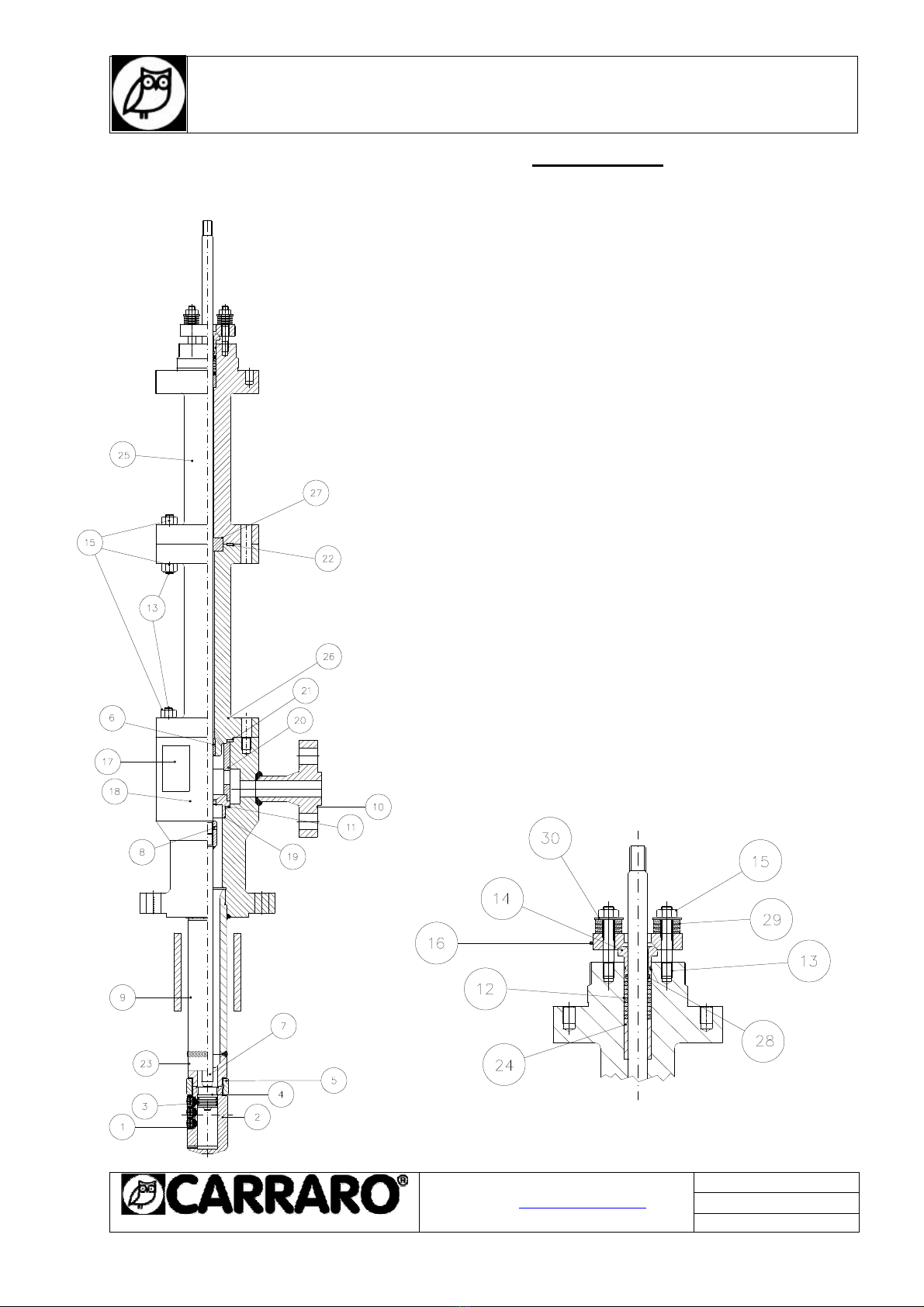
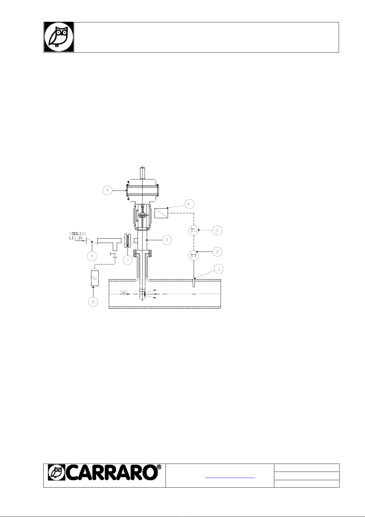
8.1 Cross-section drawings .....................................................................................8
8.2 Removing the packaging ...................................................................................9
8.3 Installation.........................................................................................................9
8.4 Start-up..............................................................................................................12
9 Maintenance........................................................................................................12
9.1 Removal ..............................................................................................................13
9.2 Disassembly........................................................................................................13
9.3 Spray cylinder......................................................................................................13
9.4 Body extension....................................................................................................14
9.5 Piston assembly...................................................................................................14
9.6 Packing gland......................................................................................................14
9.7 Re-assembly........................................................................................................14
9.8 Welding................................................................................................................15
9.9 Re-installation......................................................................................................15
10 Replacement parts...............................................................................................16
10.1 Inspection procedure ...........................................................................................16
10.2 Storage................................................................................................................16
11 Repairs................................................................................................................17
1. GENERAL INFORMATION:

I N S T R U C T I O N S
For the installation and maintenance of DC1525 - DC1550
desuperheaters
IMI0049E.doc
Rev.0 20/08/14
20090 SEGRATE (MI)- via E.Fermi
EMAIL: [email protected]
TEL.(02) 269912.1 - FAX.(02) 2692.2452
Page 3 of 16
1.1. - RIGHT TO MAKE MODIFICATIONS AND "COPYRIGHT"
The regulations, standards etc. quoted in these instructions are valid at the time of preparation of this
document and are not subsequently updated. It is the duty of the user to take full responsibility for
applying the most up-to-date version of the standards and regulations in question.
The supplier reserves the right to make changes and technical improvements to data and information
whenever it sees fit to do so. The user shall on no account be entitled to claim a right of modification or
improvement in relation to desuperheaters already supplied.
2. GUARANTEE
The extent and duration of the guarantee are defined in the manufacturer's “General Conditions of Sale”.
The applicable conditions are those stipulated in the most up-to-date version in existence at the time of
delivery.
The guarantee does not cover, amongst other cases, damage to valves caused by the following:
°Ignorance of or non-compliance with these instruc tions for use!
°The work of personnel insufficiently qualified to undertake fitting, use or maintenance;
°Normal wear;
°Erroneous or negligent use of the desuperheaters.
The guarantee shall not be valid and the manufacturer shall accept no responsibility in the event of:
°Non-compliance with regulations for the preventio n of accidents and/or safety standards;
°Imperfect installation, poor commissioning and in correct use;
°Improper or incorrect use, inappropriate applicat ion or work conditions differing from those agreed.
The user shall bear sole responsibility in the event of physical and/or material damage deriving from
failure to observe the above.
3. VALIDITY OF INSTRUCTIONS
These instructions relate to variable area desuperheaters:
•DC1525 - DC1550 S
EE
P
ARAGRAPH
8)
(Fig.1)

I N S T R U C T I O N S
For the installation and maintenance of DC1525 - DC1550
desuperheaters
IMI0049E.doc
Rev.0 20/08/14
20090 SEGRATE (MI)- via E.Fermi
EMAIL: [email protected]
TEL.(02) 269912.1 - FAX.(02) 2692.2452
Page 4 of 16
4. PRODUCT SAFETY INDICATIONS AND TAG SYSTEM
If and where appropriate, safety indications have been put inside tags on the sides of the pages of this
manual.
These rectangular tags are placed vertically (as shown in the following examples) and contain four
different messages communicating:
- The level of risk;
- The nature of the risk;
- The effects of the risk on people or products;
- Instructions, if necessary, on how to avoid the risk.
The box at the top contains a warning word (DANGER – WARNING – CAUTION – ATTENTION) which
indicates the level of risk.
The box in the middle contains a drawing indicating the nature of the risk and its possible effects on
people and property. In some cases, the drawing may suggest what preventive measures can be taken,
such as wearing safety clothing.
The box at the bottom may contain a message with instructions on how to avoid the risk. In the event of
risks for people, the message may also contain a more precise definition of the risk and its effects on
people.
1) DANGER – Immediate risk which will certainly cause serious
injury or death.
2) WARNING – Risk or hazardous behaviour which may cause
serious injury or death.
3) CAUTION – Risk or hazardous behaviour which may cause
minor injury.

I N S T R U C T I O N S
For the installation and maintenance of DC1525 - DC1550
desuperheaters
IMI0049E.doc
Rev.0 20/08/14
20090 SEGRATE (MI)- via E.Fermi
EMAIL: [email protected]
TEL.(02) 269912.1 - FAX.(02) 2692.2452
Page 5 of 16
5. SAFETY WARNINGS
Thorough maintenance operations and overhauls are important for the safe and reliable operation of all
desuperheaters.
The service procedures recommended by CARRARO and described in this manual are effective methods
for carrying out maintenance operations. Please note that this service manual contains various warning
and caution notices which should be read carefully in order to minimise the risk of injury to people or the
possibility of using incorrect work methods which may damage the desuperheaters or make them unsafe.
It is important to realise, however, that these warnings cannot be exhaustive.
CARRARO is unable to know, assess and inform customers or users of all the conceivable methods of
performing maintenance operations and all the risks deriving from the use of such methods.
Consequently, CARRARO has not even attempted to start such a task. Therefore, whoever uses a
service method or piece of equipment which is not recommended by CARRARO must make sure that
neither his own or other people's safety, nor desuperheater safety and performance are jeopardised by
the chosen method.
In case of doubt about the method used, please contact CARRARO.
Take all safety precautions while testing, installing or dismounting the product; these include, wearing ear
plugs, goggles and safety clothing, such as gloves, both in or near the work area.
Given the large number of conditions and circumstances that may arise while working on the products
and the consequent risks deriving from the way this is done, CARRARO is not able to prevent all risks of
injury to people and damage to property and can only help by asking you to take the utmost care and
giving you the following safety suggestions.
Users of CARRARO products are responsible for training the staff that will use the product.
It is most important for these people to acquire a thorough knowledge of the instructions relative to the
product, especially the ones contained in this manual.

I N S T R U C T I O N S
For the installation and maintenance of DC1525 - DC1550
desuperheaters
IMI0049E.doc
Rev.0 20/08/14
20090 SEGRATE (MI)- via E.Fermi
EMAIL: [email protected]
TEL.(02) 269912.1 - FAX.(02) 2692.2452
Page 6 of 16
6. SAFETY PRECAUTIONS
Always follow the safety regulations applicable to the plant and observe the
following precautions:
° Wear protective clothing. Hot water causes burns and superheated
vapour is invisible.
° Before starting disassembly, make certain that the desuperheater is
isolated from any source of pressure that may exist within the system.
° Carry out checking/maintenance of desuperheaters at least once two
years.
° The outer surfaces of desuperheaters reach temperatures approximately
equal to the temperature of the fluid flowing through them. For this reason,
if fitting a desuperheater in a potentially explosive atmosphere, check that
the explosion point of the atmosphere surrounding the desuperheater is
sufficiently higher than fluid temperature inside the desuperheater itself,
and prevent deposits of dust from forming on its outer surfaces.
° In the connection between the desuperheater and line, ensure the
equipotentiality of the system in order to prevent the accumulation of
electro-static charges on the outer surfaces of the plant, which could act as
an effective trigger in a potentially explosive atmosphere.
° Before carrying out any work on desuperheater components, consult
CARRARO.

I N S T R U C T I O N S
For the installation and maintenance of DC1525 - DC1550
desuperheaters
IMI0049E.doc
Rev.0 20/08/14
20090 SEGRATE (MI)- via E.Fermi
EMAIL: [email protected]
TEL.(02) 269912.1 - FAX.(02) 2692.2452
Page 7 of 16
7. TRANSPORT, STORAGE AND HANDLING
Transport
Carraro DS desuperheaters are packed with the utmost care in wooden
crates or cardboard boxes so that they are protected during handling and
transport to their place of installation. The connections are protected to
prevent the entry of dirt. Follow any directions marked on the packaging.
ATTENTION!
Personnel assigned to load-handling activities must take
all the necessary safety precautions.
Storage
The desuperheaters must be stored in a dry environment and protected
against atmospheric conditions. They must not be removed from their
crates or packaging until immediately before installation.
The protective materials on the connections must be left in place until the
last minute. Whether packed or not, the desuperheaters must not be
subject to violent impacts.
Whether packed or not, the desuperheaters must always be stored in an
upright position, i.e. never laid on one side, in order to prevent distortion
or damage to internal components.
Handling
When removing desuperheaters from their packaging and removing the
protective materials from the connections immediately prior to installation,
take the utmost care to prevent foreign matter from entering inside the
desuperheater.
ATTENTION!
When handling desuperheaters, keep the work area clear
in order to prevent damage to property
or injury to persons.

I N S T R U C T I O N S
For the installation and maintenance of DC1525 - DC1550
desuperheaters
IMI0049E.doc
Rev.0 20/08/14
20090 SEGRATE (MI)- via E.Fermi
EMAIL: [email protected]
TEL.(02) 269912.1 - FAX.(02) 2692.2452
Page 8 of 16
8 INSTALLATION AND ASSEMBLY INSTRUCTIONS
DC1525 – DC1550
8.1 Cross-section drawings
• DC1525/IF1 – DC1550/ IF1
Pos. Part name Material
1+ 2 •Spray nozzle assembly AISI 316L
3 •Piston ring Aluminium bronze
4 •Piston AISI 316L
5 •Fastener ring Nitronic 60
6 Bushing Nitronic 60
7 •Stem AISI 316
8 •Plug AISI 316L
9 Body pipe AISI 316L
10 Liquid flange AISI 316L
11•Gasket PTFE + AISI 316L
12 • Packing set PTFE
13 Stud A-193 B8M
14• Follower AISI 316
15 Nut A-194 8M
16 Packing flange AISI 304
17 Nameplate AISI316L
18 Body AISI 316L
19• Seat AISI 316L
20 Cage AISI 316
21• Gasket PTFE +AISI 316L
22• Gasket PTFE + AISI 316L
23 Extension AISI 316L
24• Spacer Aluminium bronze
25 Bonnet AISI 316L
26 Extension AISI 316L
27• Bushing PTFE
28• O-rings Silicone
29 Disc Spring AISI 316L
30 Spacer AISI316L
• RECOMMENDED SPARE PARTS
Fig.1 – section and packing details

I N S T R U C T I O N S
For the installation and maintenance of DC1525 - DC1550
desuperheaters
IMI0049E.doc
Rev.0 20/08/14
20090 SEGRATE (MI)- via E.Fermi
EMAIL: [email protected]
TEL.(02) 269912.1 - FAX.(02) 2692.2452
Page 9 of 16
8.2 REMOVING THE PACKAGING
Carraro DC desuperheaters are packed with the utmost care in wooden crates or cardboard boxes so
that they are protected during handling and transport to their place of installation. After hydrostatic testing,
the desuperheater is flushed and carefully dried to protect the internal surfaces. Should any damage
occur during transport, however, the transport company or a representative of Carraro must be notified
immediately. Remove the packaging with care, then check that the surfaces of the flanges, threads,
actuators, connection pipes, etc. are not damaged (see Fig. 1).
8.3 INSTALLATION
Before installation, visually inspect the desuperheater, the actuator and any accessories, to make certain
that they are not damaged. Check that the information given in the documentation and on the data plate,
and the tag number correspond to the specifications of the order. Remove the desuperheater from its
package by lifting it with slings (for heavy loads) wrapped round its body. Do not lift the unit by the liquid
inlet connection, the actuator or other accessories. Do not remove the flange coverings until immediately
before installation.
During installation of the desuperheater, use gaskets and fasteners which comply with the appropriate
standards. Position the gasket on the mounting flange and gently insert the nozzle into the secondary
pipe. Before tightening the studs, check that the spray cylinder is directed in the same direction as the
process gas flow (see Fig. 2).
The desuperheater must not be installed in such a way that it is subject to tensions, forces and torque.
- Liquid flange positions -
PFAn PFAe PFAs PFAw
- Handwheel positions -
PVn PVe PVs PVw
Fig. 2
The DC desuperheater has a standard lower body length as specified in the contractual drawings,
whereas the mounting trunk of the process pipe must be made to measure. The length of this secondary
pipe must be such that the central axis of the spray cylinder corresponds with the central axis of the
vapour line (±5 mm). The nominal diameter of the mounting trunk must be as follows: for DC1525 25 m
3
/h

I N S T R U C T I O N S
For the installation and maintenance of DC1525 - DC1550
desuperheaters
IMI0049E.doc
Rev.0 20/08/14
20090 SEGRATE (MI)- via E.Fermi
EMAIL: [email protected]
TEL.(02) 269912.1 - FAX.(02) 2692.2452
Page 10 of 16
version - 3” (DN 80), with maximum tube schedule of 160; for DC1550 50 m
3
/h version - 4” (DN 100) with
maximum tube schedule of 160.
The minimum length of tube required downstream varies according to application and is specified by
Carraro in the respective quote. This length without bends is necessary to prevent erosion caused by
drops of liquid deposited on the walls of the pipes, the valves and the fittings, and is normally a minimum
of 4, 6 m (a straight length of pipe is not generally necessary upstream). The distance that separates the
desuperheater from the temperature sensor is between 12 and 15 m, although the specific distance for
the application is generally specified in the quote.
Longer distances ensure complete evaporation of the liquid at lower process gas speeds. The
temperature sensor must be located in the top half of the pipe. Avoid fitting branches of the vapour pipe
between the desuperheater and the sensor (see Fig. 3).
1) Temperature sensor
2) Temperature transmitter
3) Temperature control
4) Varicryo
5) Actuator
6) Positioner
7) Filter (Optional)
8) Auxiliary N2
9) Check valve
Fig. 3
The unit can be fitted on either horizontal or vertical pipes. The direction of liquid injection must
correspond to the direction of process gas flow. The desuperheater can be fitted at 90° to the vapour
pipe, regardless of direction of flow. The allowed orientations are outlined in Fig. 4. Vertically downwards
position must be achieved If installed horizontally, the unit must be mounted with a weight-compensation
system.

I N S T R U C T I O N S
For the installation and maintenance of DC1525 - DC1550
desuperheaters
IMI0049E.doc
Rev.0 20/08/14
20090 SEGRATE (MI)- via E.Fermi
EMAIL: [email protected]
TEL.(02) 269912.1 - FAX.(02) 2692.2452
Page 11 of 16
Fig. 4
The cooling fluid must be clean filtered and must be at constant pressure at all times, as specified in the
order documents. Each liquid supply line must be protected by its own filter with maximum mesh size 50
(mesh 20 acceptable for nozzles from ‘E’ upwards). On request Carraro can supply a supplementary
filter(see fig 3 item 7). The mainly application of Carraro’s filter is to clean cooling liquid from particles
during the start up operations. If no other filter system is installed this filter can be left and periodically
inspected.
As for the process gas pipe, use gaskets and fasteners which comply with the codes of the respective
pipes. The liquid supply line must be free of any trace of liquids which can solidify If necessary flushing by
appropriate medium bust be provided before connecting the mounting flange of the desuperheater (see
Fig. 3).
After desuperheater is installed a flushing by dry gas nitrogen is strongly recommended to
remove internal moisture.
8.4 START-UP
Make sure that all the components are correctly installed. The supply for the instrumentation air pipes
must be connected as indicated in the instruction manual, together with the filter regulators and valve
positioners. Similarly, calibrate the temperature control unit/transmitter in such a way that it responds
automatically to temperature variations.
Check the liquid pressure in the desuperheater and the operation of the transmitter and temperature
control unit by manually increasing and reducing the output signal and observing the temperatures shown
and recorded. Once there is satisfactory correspondence between the signals sent by the instruments
and the actual temperature, it is possible to set the regulation point and activate the system in automatic
mode.
We recommend to record the characteristics of the vapour (principally temperature) over a sufficiently
long period, in order to check the efficiency of the system and make the necessary adjustments.
9MAINTENANCE
Maintenance of the desuperheater is extremely simple and does not require specific instruments or
experience. Take extreme care when carrying out maintenance work, especially if using grinding tools ,
compressed air and rotary machinery. In this case the use of protective accessories (goggles, gloves etc.)
is strongly recommended.

I N S T R U C T I O N S
For the installation and maintenance of DC1525 - DC1550
desuperheaters
IMI0049E.doc
Rev.0 20/08/14
20090 SEGRATE (MI)- via E.Fermi
EMAIL: [email protected]
TEL.(02) 269912.1 - FAX.(02) 2692.2452
Page 12 of 16
9.1 REMOVAL
Before removing the desuperheater from the system, check that the process and liquid pipes are
completely depressurised, drained and bled. Bleed and remove the air supply line to the instrumentation.
Loose the studs on the liquid and process gas flange and remove the desuperheater from the system. It
is advisable to move the unit to a workshop.Lift the unit using suitable slings wrapped round its body. Do
not attempt to lift it by the actuator or any other accessories. The coupling of the stem varies according to
the type of actuator installed.
9.2 DISASSEMBLY
Varicryo is suitable for severe conditions of use and therefore more subject to wear parts maintenance. It
is designed in quick-change version with the possibility of easy replacement of components without trim
threaded or welded. If it is only necessary to replace the trim when the disconnected actuator can be
removed after unscrewing the cap screws (15 of item 26) and then remove from all internal
components including the seat and stem-plug assembly. They also recommend replacing all the
gaskets and piston rings.
The nozzle head can be disassembled more easily if it is positioned horizontally with the section of the
body extension firmly gripped in the vice. Grind the weld points on the nozzle, with a standard angle
grinder. Check that the weld has been sufficiently removed to allow unobstructed rotation of the tightening
ring. Unscrew the tightening ring by turning it anti-clockwise. Note that the body extension has a right-
hand thread. To facilitate removal of the ring, tap it gently with a hammer. Note that the spray cylinder has
a left-hand thread. In the event of difficulty in removing the tightening ring, grind it at two diametrically
opposed points. Take care not to damage the thread of the body and of the cylinder (see Fig. 6).
Fig. 6

I N S T R U C T I O N S
For the installation and maintenance of DC1525 - DC1550
desuperheaters
IMI0049E.doc
Rev.0 20/08/14
20090 SEGRATE (MI)- via E.Fermi
EMAIL: [email protected]
TEL.(02) 269912.1 - FAX.(02) 2692.2452
Page 13 of 16
9.3 SPRAY CYLINDER
Once removed, inspect the inside of the cylinder and check for any surface damages, which can be
removed by polishing or grinding. The bore of the cylinder must not exceed 32 mm for the DC1525 model
and 45 mm for the DC1550 model, with maximum out-of-round of 0.25 mm. Any debris must be removed
from the nozzles with a compressed air jet. Inspect the nozzle outlet holes. These must show no signs of
elliptical wear, roughness or damage that could adversely affect their performance. Thoroughly clean the
thread of the cylinder, filing it with a small file where necessary.
9.4 BODY EXTENSION
Examine the thread of the body extension and adjust it by file, if necessary.
9.5 PISTON ASSEMBLY
Extract the piston and stem. The piston and stem are always supplied as a single assembly. If the piston
shows no signs of wear, it can be re-used. Replace the piston rings each time the unit is disassembled,
taking care not to overload the rings during fitting. Position the grooves in the piston rings in such a way
that they are at 120°to each other.
9.6 PACKING
Remove all the rings and components of the sealing system from the valve body. Thoroughly clean the
gland with a rotary metal brush and/or a honing tool. The area must be kept clean in order to ensure that
the valve seals correctly. Do not use grease or lubricants in the area of the sealing system. Always use
original Carraro components supplied as a set (see Fig. 7). Take care that there are six soft PTFE rings
and three solid PTFE rings. See the figure for a correct installation. Then assembly the follower with the
two O-rings. You can assembly the packing flange, the studs and the washer springs in series.
Fig. 7

I N S T R U C T I O N S
For the installation and maintenance of DC1525 - DC1550
desuperheaters
IMI0049E.doc
Rev.0 20/08/14
20090 SEGRATE (MI)- via E.Fermi
EMAIL: [email protected]
TEL.(02) 269912.1 - FAX.(02) 2692.2452
Page 14 of 16
9.7 RE-ASSEMBLY
Before refitting the valve, lubricate all the threads. Apply a thin layer of compound to the piston rings to
prevent scoring. Position the grooves in the piston rings in such a way that they are at 120°to each other.
Re-assemble the spray cylinder to the body extension. Use a fine abrasive paste to hone the seat of the
cylinder and the body extension. As the seal is metal on metal, a perfectly concentric area of the seat is
essential. Always use a new tightening ring. Position the spray cylinder so that it is correctly oriented (the
injected liquid must be in the same direction as the vapour flow), then tighten the tightening ring.
9.8 WELDING
Once re-assembled, weld the spray cylinder for improved safety. It is imperative that this operation be
undertaken by a skilled welder. A welding procedure specification is available from Carraro on request.
Both TIG and ARC welding are acceptable, and the recommended electrode material is ER NiCrMo3.
At least 2 tack welds are necessary. They must be 8 mm in length and diametrically opposed. One weld
must secure the fastener ring to the body extension, and the other must secure the spray cylinder to the
fastener ring. On completion, check the welding using appropriate penetrating liquids. There must be no
cracks. If necessary, grind and check again until the weld is satisfactory (see Fig. 8).
Fig. 8
9.9 RE-INSTALLATION
Refit the actuator to the desuperheater, referring to the data noted during disassembly when repositioning
the stem. Before re-installing the desuperheater check that the surfaces of the unit connection flanges are
completely clean. Insert the desuperheater in the vapour pipe and check that the nozzle is correctly
oriented, with the spray in the direction of the process gas flow. Lubricate the nuts and studs with a
suitable lubricant for operation temperatures and tighten uniformly, in accordance with the manufacturer’s
instructions. Before connecting the liquid supply line, flush the pipe and check that there are no
restrictions and no contamination.

I N S T R U C T I O N S
For the installation and maintenance of DC1525 - DC1550
desuperheaters
IMI0049E.doc
Rev.0 20/08/14
20090 SEGRATE (MI)- via E.Fermi
EMAIL: [email protected]
TEL.(02) 269912.1 - FAX.(02) 2692.2452
Page 15 of 16
10 SPARE PARTS
When ordering spare parts, check and specify the identification number of the unit (shown on the data
plate). For a cross-section drawing, see Fig. 1.
10.1 INSPECTION PROCEDURE
The spray nozzles (1) and (2), the fastener rings (5), the piston (4) and the piston rings (3) are
components subject to wear. The materials selected must be suited to the conditions of service of
applications on gas/liquid. It is also advisable to bear in mind that the temperature changes that take
place at the desuperheaters are generally the largest in the whole plant. After the first year of service, you
are advised to check the condition of the spray nozzle assembly, the integrated injection nozzles, fastener
ring and the welds. At the time of inspection, use penetrating liquids to check that these components are
not cracked. Components with signs of cracking must not be re-used. Every two years of service
inspection is recommended to be sure the nozzles are free from defects.
In any case it is recommended to replace the above components at least every five years of service.
Note:After each maintenance operation, restore your stock of spare parts. Please take into account that
the delivery time of special spray nozzle assemblies designed for a particular type of service is 8 weeks.
10.2 STORAGE
At the time of receipt, check that the crate and the desuperheater are free from damage. If you find
damage to either the product or the package, notify a Carraro representative immediately. Before
stocking the equipment, repair any superficial damage to the packaging in order to prevent the entry of
dust or liquid. Check the information shown on the data plate and in the documentation, then return the
units to their respective boxes/crates with the protective materials in place. In the event of short-term
storage (up to 6 months), no additional conservation measures are necessary. Store the units in their
original packing in a clean, dry, indoor place.. Check that the desuperheater is completely dry and free
from humidity. Apply a layer of lubricant, such as Cosmo, to machined surfaces, to the valve plunger and
to the gland. Store the desuperheaters in their original packing and inspect them every 3 months to check
their condition. Before putting the desuperheaters in service, replace the sealing system and check the
soundness of all components, such as the actuator seals, etc. in order to ensure correct operation. Follow
the installation procedure shown in the use and maintenance manual.
ATTENTION!
Should it be necessary to weld the pipes, avoid connecting the
earth connection to the valve, as this could cause damage to
important sliding parts.
11 REPAIRS
11.1 If it is not possible to eliminate the problems, send faulty desuperheaters to the
supplier/manufacturer, together with a description of the problem.

I N S T R U C T I O N S
For the installation and maintenance of DC1525 - DC1550
desuperheaters
IMI0049E.doc
Rev.0 20/08/14
20090 SEGRATE (MI)- via E.Fermi
EMAIL: [email protected]
TEL.(02) 269912.1 - FAX.(02) 2692.2452
Page 16 of 16
11.2 In order to receive spare parts or information, always indicates the serial number shown on the
name plate attached to the desuperheater.
11.3 Name plate (example)
11.4 To ensure the desuperheaters treated in this manual work correctly, they should be serviced by
Carraro engineers or by Carraro-authorised Service Centres using original spare parts.
ATTENTION!
The manufacturer accepts no responsibility if modifications to the
product or operations not described in this manual are carried out.
This manual suits for next models
1
Table of contents
Other CARRARO Heater manuals
Popular Heater manuals by other brands

Munters
Munters GRY-D instruction manual

GÜDE
GÜDE GFW 520 Translation of the original operating instructions

DAY Useful Everyday
DAY Useful Everyday 69651 instruction manual

Flowpro
Flowpro 84636 instruction manual

Harvia
Harvia sentiotec Concept R combi black Instructions for installation and use

One to One
One to One MO-36E-18Y Installation & operation manual