INTRODUCTION
General— The 16JB machine is factory assembled, wired
and leak tested. Installation (not by Carrier) consists prima-
rily of establishing water and electrical services to the ma-
chine. Rigging, installation, field wiring and field piping are
the responsibility of the contractor and/or customer. Carrier
has no installation responsibilities for the equipment. The
scope of Carrier’s duties at time of start-up are listed in In-
troduction portion of the 16JB Start-Up, Operation and Main-
tenance Instructions.
Job Data — Necessary information consists of: Machine
location drawings, piping drawings, field wiring diagrams
and rigging guide.
RECEIVING AND INSTALLATION
Step 1 — Check Equipment
IDENTIFY MACHINE — The machine model number and
serial number are stamped on machine identification plate.
Check this information against shipping papers and job data.
INSPECT SHIPMENT — The machine is at a deep
vacuum when shipped. Do not open any valves until the vacuum
has been noted. Refer to Shipping Vacuum Check.
Inspect for shipping damage while machine is still on ship-
ping conveyance. If machine appears to be damaged or has
been torn loose from its anchorage, have it examined by trans-
portation inspectors before removal. Forward claim papers
directly to transportation company. Manufacturer is not re-
sponsible for any damage incurred in transit.
Check all items against shipping list. Immediately notify
the nearest Carrier Air Conditioning office if any item is
missing.
To prevent loss or damage, leave all parts in original pack-
ages until installation.
CHECK SHIPPING VACUUM — To check for leaks that
have occurred during shipment:
a. Connect an absolute pressure gage to places listed in
Table 1.
b. Record the absolute pressure of each assembly. If ves-
sel pressure is greater than 0.28 in. (7mm) of mercury,
the machine has acquired a leak in shipping, and must
be leak tested. Refer to the Machine Leak Test proce-
dure for instructions.
Table 1 — Absolute Pressure Gage
Test Connections
UNIT
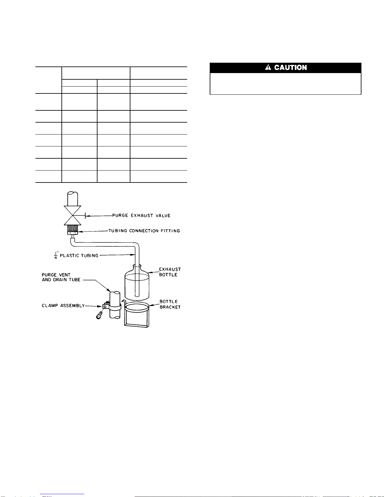
16JB GAGE CONNECTION
010-047 At auxiliary evacuation valve (item 9, Fig.1)
054-068
Generator-Condenser: At condenser-purge
suction line (Fig. 2)
Absorber-Evaporator: At auxiliary evacuation
valve (item 9, Fig. 1)
STORAGE PROTECTION — If the machine is not going
to be installed immediately, it is very important to use a drop
cloth or plastic covering to protect the machine from con-
struction dirt and moisture before installation. Also, do not
remove protective shipping cover on control panel until ready
to use.
Step 2 — Rigging and Installation
PREPARING 2-PIECE UNIT — Two-piece units must be
prepared for installation before they can be rigged.
1. Open auxiliary evacuation valve to break vacuum in
absorber-evaporator shell.
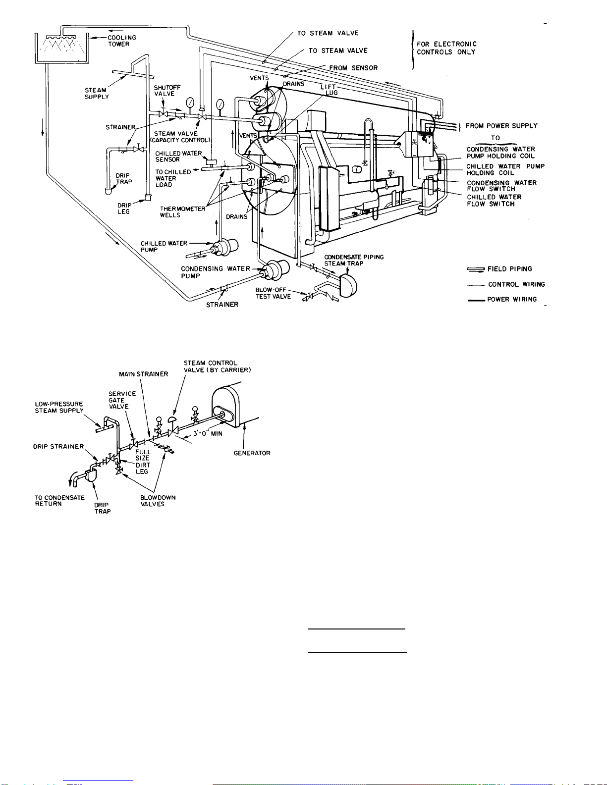
2. Open shipping valve (Fig. 2) on generator-condenser
assembly.
3. Protect machine insulation with a leather or wet canvas
cover when welding or cutting.
4. Remove all piping end plates as shown in Fig. 2.
5. Remove the weld elbow and shipping valve on the
condenser-purge suction line.
To avoid contaminates and debris getting into chiller,
do not leave machine open any longer than necessary.
Be careful not to remove any stock from pipe ends. Do
not get slag inside machine while flame cutting.
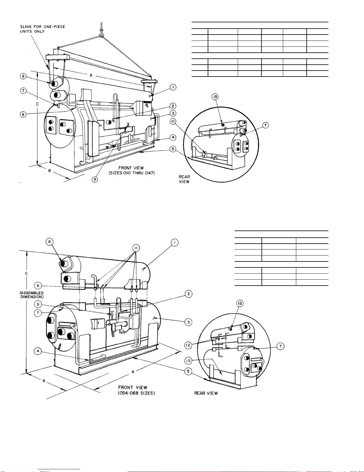
RIG MACHINE PROPERLY — Refer to rigging instruc-
tions in plastic envelope attached to machine. Rigging in-
structions vary for one-piece units and 2-piece units.
Lifting machine from points other than those specified
may result in serious damage and personal injury. Rig-
ging equipment and procedure must be adequate for ma-
chine weight. Refer to Table 2 for machine weights.
Table 2 — Rigging Weights
UNIT
16JB WEIGHT (lb) WEIGHT (kg)
1-PIECE UNITS
010 9,000 4,082
012 9,100 4,128
014 9,100 4,128
018 11,500 5,216
021 12,300 5,579
024 14,600 6,622
028 14,800 6,713
032 18,500 8,391
036 18,900 8,573
041 23,000 10,433
047 23,500 10,659
2-PIECE UNITS
Absorber Generator Absorber Generator
041 18,000 5,500 8,165 2,495
047 18,500 5,500 8,392 2,495
054 21,500 7,000 9,752 3,175
057 22,000 7,000 9,979 3,175
061 26,500 7,000 12,020 3,175
068 28,000 7,400 12,701 3,357
Rigging One-Piece Units — One-piece units consist of all
units from 010-036 and, when specified, units 041-047. Lift
with cable slings under condenser water boxes. Refer to Fig. 1.
Fig. 2 — Weld Breaking Instructions
3