If the problem continues, please visit www.cavius.
com for any trouble shooting.
8. ADD EXTRA DEVICE:
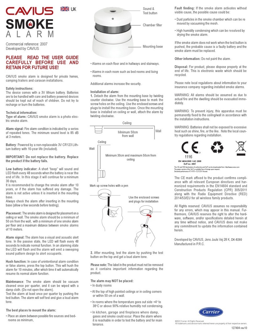
All CAVIUS interconnected alarms within the
can be added to the system as
they run on the same frequency and use the same
data protocol.This means that the wireless system
can consist of a combination of smoke, heat etc.
Place all alarms into ‘Learn Mode’ and repeat sec-
tion 1.
Always test connection to all devices by repeating
test function section 7 after adding devices.9. OTH-
ER INFORMATION:
Do not paint the alarm.
Disposal: please dispose properly at the end of life.
This is electronic waste which should be recycled.
Please note local regulations about information to
your insurance company regarding installed smoke
alarms.
Complies to the Radio Equipment Directive
2014/53/EU
RF Frequency: 868 MHz.
Maximum radio-frequency power transmitted: 20
dBm
Full DoC to 2014/53/EU (RED) can be downloaded
at www.cavius.com
WARNING: All alarms should be assumed as due
to actual re and the dwelling should be evacuated
immediately.
WARNING: To prevent injury, this apparatus must
be permanently xed to the ceiling/wall in accor-
dance with the installation instructions.
WARNING: Batteries shall not be exposed to ex-
cessive heat such as shine, re, or the like. Note
the local country regulations regarding installation.
The CE mark afxed to the product conrms
compliance with all relevant European directives
and harmonized requirements in the EN14604
standard and Construction Products Regulation
(CPR) 305/2011 along with the Radio Equipment
Directive (RED) 2014/53/EU for all wireless family
products.
All Rights reserved: CAVIUS Aps assumes no
responsibility for any errors, which may appear in
this manual. Furthermore, CAVIUS Aps reserves
the right to alter the hardware, software, and/or
specications detailed herein at any time without
notice, and CAVIUS Aps does not make any com-
mitment to update the information contained here-
in. All the trademarks listed herein are owned by
their respective owners. Copyright © CAVIUS Aps.
Developed by CAVIUS Aps, Jens Juuls Vej 28 K,
DK-8260
Manufactured in P.R.C.
Contact: CAVIUS Ltd, Edinburgh, Scotland, EH3
9DQ
Use the mounting base ring to mark the screw
holes on the ceiling or the wall.
Once the mounting base is installed, attach the
alarm by twisting clockwise until it clicks.
6. SAFETY LOCK:
7. TEST FUNCTION:
After installation, and at least once per quarter,
test all of your alarms to ensure they are operating
correctly and are within range of each other.
It is recommended to check visually every week
ifthe LED ashes correctly (every 48sec.)
Press the test button on any alarm for at least
10 seconds. This will send out a test signal
from the alarm; all other connected
alarms should receive the signal within a short
time. The alarms will emit a short beep and the
LED will ash every 8 seconds for 2 minutes.
NOTE: Test function also allows to send a deplet-
ed RF signal to ensure an optimal operation in
normal conditions.
When the test signal is sent out, the alarms will
respond in two ways:
1. A single beep every 8 seconds indicates that
the alarms are connected and functioning.
2. Three short beeps every 8 seconds indicates a
smoke sensor fault. The alarm should be cleaned
by running the vacuum (on a low setting) around
the smoke alarm chamber and tested again.
If required this indication can be stopped early on
each alarm by a short press of the test button.
TIP: It is safe to cover the sound output hole with
your nger during the testing to minimize the
sound level emitted.
HEAT ALARM
SMOKE ALARM
MAINS POWERED
SMOKE ALARM
MAINS POWERED
HEAT ALARM
USE THE
ENCLOSED
SCREWS AND
PLUGS
400146 rev10
2
CLICK THE SMOKE
ALARM FIRMLY INTO THE
BASE TO LOCK
MOUNT THE
SAFETY LOCK
The CE and RED declaration of conformity and DoP can be downloaded from: http//www.cavius.com
The paper version of the DoP is available free of charge upon request.
Declared performance 4.1-4.19 + 5.2-5.24: Passed.
1116
21
EN 14604:2005 + AC :2008
DoP no.: 2106
2
