8
5. Installation
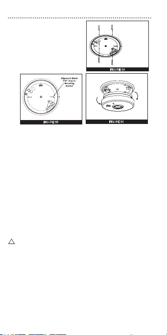
1. To ensure aesthetic alignment
of the alarm with the hallway
or wall, the “A” line on the
mounting bracket should be
parallel with the hallway when
ceiling mounting or horizontal
when wall mounting.
!
2. After selecting the proper smoke alarm location as described in on
Page 2, attach the mounting bracket to the ceiling as shown in
Figure 2A. For wall mounting see Figure 3A. Place the mounting plate
on the wall; be sure the “A” line is horizontal (parallel to the oor).
Use the screws and cavity xings provided to secure the mounting
bracket (use 3/16” drill bit for cavity xings.).
3. This alarm has a battery permanently sealed inside the alarm. No
battery installation or maintenance is necessary.
Note: Extensive cycling between high and low temperatures will
signicantly reduce battery life. Long term exposure to high
temperatures will degrade the battery over time. Chubb recommends
locating this alarm in a controlled temperature environment (20-30°C)
for optimum life.
ACTIVATING THE ALARM
Once activated, the battery will supply power to the alarm for the life
of the alarm (10 years). Ensure that the mounting bracket is mount-
ed correctly before installing the alarm on the mounting bracket.
1. To activate the alarm, install the alarm on the mounting bracket (Figure
3C) and rotate the alarm clockwise (as indicated on the alarm cover)
until the alarm snaps into place.
WARNING: Alarm will not operate if it is not xed on mounting plate.
2. After installation/activation, test your alarm by depressing and
holding down the Test button for a minimum of 1 second (or until the
alarm sounds). This should sound the alarm. The alarm will sound at a
low level to avoid discomfort. If the Test button is pressed for greater
than 5 seconds, the alarm will sound at the full 85 decibels and may
cause some discomfort.
Smoke Alarm Tamper Resist Feature
•
To make the smoke alarm tamper-resistant, a tamper resist feature has been
provided. To activate this feature you must break out the tamper-resist posts
on the mounting plate (Figure 4A).Use a small screwdriver.
• Using this feature will deter children and others from removing the alarm from
the mounting plate. With the blocks removed, the tamper-resist feature will be
activated when the alarm is installed on the mounting plate.
FIGURE 3A
When mounting
in a hallway,
the “A” line
should be
parallel with the
hallway.
FIGURE 3B
When wall
mounting, the
“A” line should
be horizontal.
FIGURE 3C
Remove
Install
FIGURE 3A
When mounting
in a hallway,
the “A” line
should be
parallel with the
hallway.
FIGURE 3B
When wall
mounting, the
“A” line should
be horizontal.
FIGURE 3C
Remove
Install