PSA Products homeguard HG1000 User manual

MODEL HG1000
I STALLATIO A D USER MA UAL
SMOKE ALARM IO ISATIO DESIG
IMPORTA T: READ ALL I STRUCTIO S BEFORE I STALLATIO .
O USER REPLACEABLE PARTS I SIDE THIS SMOKEALARM.
WAR I G: Disconnecting smoke alarm from mounting base and/or removing the 9V battery
will render this smoke alarm inactive.
240VAC MAI S POWERED SI GLE STATIO A D/OR I TERCO ECTABLE
(24 U ITS) IO ISATIO SMOKE ALARM. 9V REPLACEABLE BATTERY
BACKUP . TEST A D HUSH CO TROL A D LOW BATTERY I DICATIO .
SPECIFICATIO
ELECTRICAL RATI G: 240VAC 50Hz, 80mA per alarm and interconnectable to
24 alarms.
WAR I G: THIS SMOKE ALARM MUST O LY BE WIRED TO A
240Vac 50Hz SI E WAVE CURRE T SUPPLY.
THE SMOKE ALARM USES A EXTREMELY SMALL AMOU T OF A
RADIOACTIVE I THE IO ISATIO CHAMBER.
1299-7201-01:_ 2014.5.7 10:40 AM Page 1

RECOMMENDED LOCAT ONS OF ALARMS ................................................................................1
MOB LE HOME NSTALLAT ON.................................................................................................................3
AVO D THESE LOCAT ONS............................................................................................................................. 3
FALSE ALARMS.............................................................................................................................................................4
HOW TO REMOVE SMOKE ALARM FROM BASE PLATE..............................................5
NSTALLAT ON...............................................................................................................................................................5
OPERAT ON, TEST NG AND MA NTENANCE..........................................................................11
BATTERY NSTALLAT ON, REPLACEMENT AND TEST..............................................14
REPA RS AND SERV CES..................................................................................................................................15
GOOD SAFETY HAB TS.....................................................................................................................................15
THE L M TAT ONS OF SMOKE LARMS..........................................................................................15
OPERAT NG PR NC PLES OF SMOKE ALARMS....................................................................17
DEVELOP AND PRACT CE A PLAN OF ESCAPE...................................................................18
WHAT TO DO WHEN THE ALARM SOUNDS.............................................................................19
NSTALLER PLEASE NOTE...........................................................................................................................20
WARN NG: NSULAT ON TEST.................................................................................................................20
WARRANTY AND L AB L TY.....................................................................................................................21
CO TE TS
1299-7201-01:_ 2014.5.7 10:40 AM Page 2

1
1. RECOMME DED LOCATIO S OF ALARMS
1.1 Locate an alarm for each separate sleeping area in the immediate vicinity of
the bedrooms. Try to monitor the exit path as the bedrooms are usually far-
thest from an exit. f more than one sleeping area exit, locate additional
alarms in each sleeping area in the immediate vicinity bedrooms.
1.2 Locate additional alarms to MON TOR any stairway as stairways act like
chimneys for smoke and heat.
1.3 Locate at least one alarm on every floor level.
1.4 Locate an alarm in every room where a smoker sleeps.
1.5 Locate an alarm in every room where electrical appliances are operated (i.e.
portable heaters or humidifiers).
1.6 Locate an alarm in every room where someone sleeps with the door closed.
The closed door may prevent an alarm not located in that room from waking
the sleeper.
1.7 Smoke, heat and other combustion products rise to the ceiling and spread
horizontally. Mounting the alarm on the ceiling in the center of the room
places it closest to all points in the room. Ceiling mounting is preferred in
ordinary residential construction.
1.8 For mobile home installation select location carefully to avoid thermal
barrier that may form at the ceiling. For more details see Mobile Home n-
stallation (Section 2).
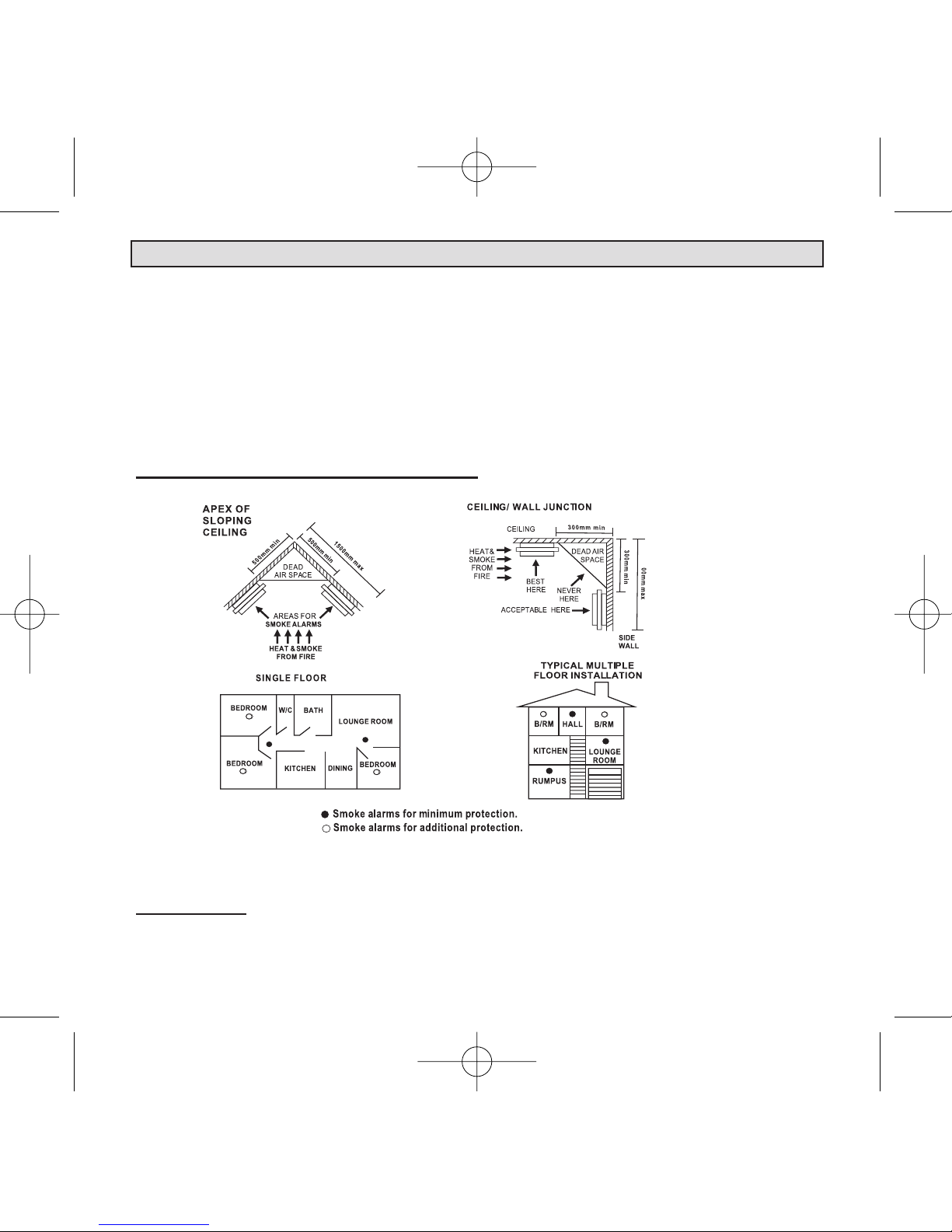
1.9 When mounting alarms on the ceiling locate it at least 300mm away from the
side wall and 300mm away from any corner. (see diagram)
1.10 When mounting alarms on a wall, use the inside wall. The recommended
position is between 300mm and 500mm off the ceiling. (see diagram)
OTE: The performance of smoke alarms mounted on walls is unpredictable
and this mounting position is not recommended when ceiling mounting can be
implemented.
1299-7201-01:_ 2014.5.7 10:40 AM Page 1
2
1.11 When mounting the alarm at the apex of a sloping ceiling it should be
located at least 500mm away from the apex but should not exceed
1500mm (see diagram).
1.12 Locate smoke alarm at both ends of a bedroom hallway or large room
if the hallway or room is more than 9m long.
1.13 Do not locate smoke alarms in kitchen areas due to potential nuisance
alarms from cooking fumes.
1. RECOMME DED LOCATIO S OF ALARMS
5
I STALLATIO OF SMOKE ALARM
IMPORTA T: I CORRECT ORIE TATIO OF SMOKE ALARM MAY DECREASE
OPERATIO AL EFFECTIVE ESS
1299-7201-01:_ 2014.5.7 10:40 AM Page 2

3
2.1 Modern mobile homes have been designed and insulated to be energy effi-
cient. nstall smoke alarms as recommended (refer to RECOMMENDED
LOCAT ONS).
2.2 n older mobile homes that are not well insulated compared to present stan-
dards, extreme heat or cold can be transferred from the outside through
poorly insulated walls and roof. This may create a thermal barrier which can
prevent smoke from reaching a smoke alarm mounted on the ceiling. n such
units, install smoke alarm on inside partition between 300mm and 500mm
from the ceiling.
2.3 f you are not sure about the insulation in your mobile home, or if you notice
the walls and ceilings are either hot or cold, install alarm on an inside wall.
For minimum protection, install one alarm close to the bedrooms.
For additional protection, see SI GLE FLOOR PLA .
OTE:TEST YOUR SMOKE ALARM OPERATIO AFTER MOBILE
HOME VEHICLE HAS BEE I STORAGE, BEFORE EACH TRIP
A D AT LEAST O CE WEEK DURI G USE.
2. MOBILE HOME I STALLATIO
3. AVOID THESE LOCATIO S
3.1 Do not locate your alarm in the garage - products of combustion are present
when you start your automobile. Use Heat Alarm in this location.
3.2 Do not locate your alarm in front of forced air supply ducts used for heating
and air conditioning and other high air flow areas.
3.3 Do not locate your alarm less than 500mm from the peak of an "A" frame
type ceiling.
3.4 Do not locate your alarm in areas where temperatures may fall below 5°C or
rise above 45°C, or in humidity higher than 85% as these conditions may
reduce battery life.
1299-7201-01:_ 2014.5.7 10:40 AM Page 3

4
3.5 Avoid dusty areas, dust particles may cause smoke alarm to false alarm or
fail to alarm. Use Heat Alarm in this location to avoid false alarms.
3.6 Avoid very humid areas or near a bathroom, moisture can cause false alarm.
3.7 Avoid insect-infested areas.
3.8 Do not locate alarm within 0.9m of the following: the door to a kitchen, the
door to a bathroom containing a tub or shower, ceiling or whole house venti-
lating fans, or other high flow areas.
3.9 Avoid locating near fluorescent lights or other electrical equipment. Electronic
magnetic interferences or “noise” may cause nuisance alarms or chirping.
3.10 Smoke alarms are not to be used with detector guards unless the combination
(alarm and guard) has been evaluated and found suitable for that purpose.
3. AVOID THESE LOCATIO S
4. FALSE ALARMS
4.1 This smoke alarm is designed to minimize false alarms. Smoking will not
normally set off the alarm unless smoke is blown directly into the alarm.
4.2 Combustion particles from cooking may set off the alarm if the alarm is
located close to the kitchen cooking surface.
4.3 Large quantities of combustion particles are generated from spills and
over-boil.
4.4 An alarm with a Hush® Control device is preferable near a kitchen
environment for this reason.
4.5 Photo-electric type smoke alarms are less prone to false alarm near kitchen
areas than ionisation type smoke alarms.
4.6 f the alarm does sound, check for fire first. f a fire is discovered, escape
quickly and call the Fire Brigade. f no fire is present, check to see if one of
the reasons listed above may have caused the alarm.
1299-7201-01:_ 2014.5.7 10:40 AM Page 4

5
5. HOW TO REMOVE SMOKE ALARM FROM BASE PLATE
5.1 f the smoke alarm tamper resist feature has been installed, refer to the
AlarmTamper Resist Feature section for removal instructions.(See page 10)
5.2 To remove the alarm from the mounting plate, rotate the alarm in the direc-
tion of the "OFF" arrow on the cover.
5.3 To disconnect the AC Quick-Connect wire
harness, squeeze the locking arms on the
sides of the Quick Connector while pulling
the connector away from the bottom of the
alarm (see mage 1B).
6. I STALLATIO
WAR I G: THIS SMOKE ALARM MUST BE I STALLED BY QUALIFIED
(LICE SED) ELECTRICIA S O LY.
6.1 Wiring Instructions:
6.1.1 n the interests of safety, this smoke alarm and all wiring must be installed by
a licensed electrician in accordance with the relevant requirements of the
SAA Wiring Rules - AS3000.
6.1.2 DO NOT connect this smoke alarm on the base plate without the presence of
240V mains power.
OFF
ON
ROTATE TO MOUNT OR
TO REMOVE
1299-7201-01:_ 2014.5.7 10:40 AM Page 5

6
6.1.3 This Smoke Alarm can only interconnect with Homeguard Model HG1000.
nterconnection with other brands may cause damage or result in a shock or
fire risk and void warranty.
6.1.4 Due to “noise” from electromagnetic interference, up to 24 units of smoke
alarms may be interconnected.
6.1.5 There are three terminals in the supply terminal block, marked A, S, N. t is
important that the alarm be wired correctly to ensure correct operation.
ncorrect wiring to the Smoke Alarm will damage the unit and void the war-
ranty.
6.1.6 A total maximum of 250 meters (820 feet) of wire can be used in
interconnecting smoke alarms.
6.1.7 All final sub-circuit conductors including the signal conductor must be a
minimum size of 1mm² with 250V grade insulation.
6.1.8 nterconnected Smoke Alarms must be connected to the same final subcircuit.
6.1.9 Do not use any wire that could later be confused with the normal house wires
for the interconnect wire. For example, green/yellow earth wire.
6.1.10 Do not connect AC power wires to S interconnect terminal. These will damage
smoke alarms.
6.1.11 Do not connect the S interconnect wire to any device, except the S intercon-
nect terminal of smoke alarm. Otherwise, smoke alarm will be damage.
6.1.12 Smoke alarms should be interconnected only within the confines of a single
family living unit. f smoke alarms are interconnected between different units,
there may be excessive nuisance alarms. Residents may not be aware that
smoke alarms are being tested or that it is a nuisance alarm caused by cooking,
etc.
6. I STALLATIO
1299-7201-01:_ 2014.5.7 10:40 AM Page 6
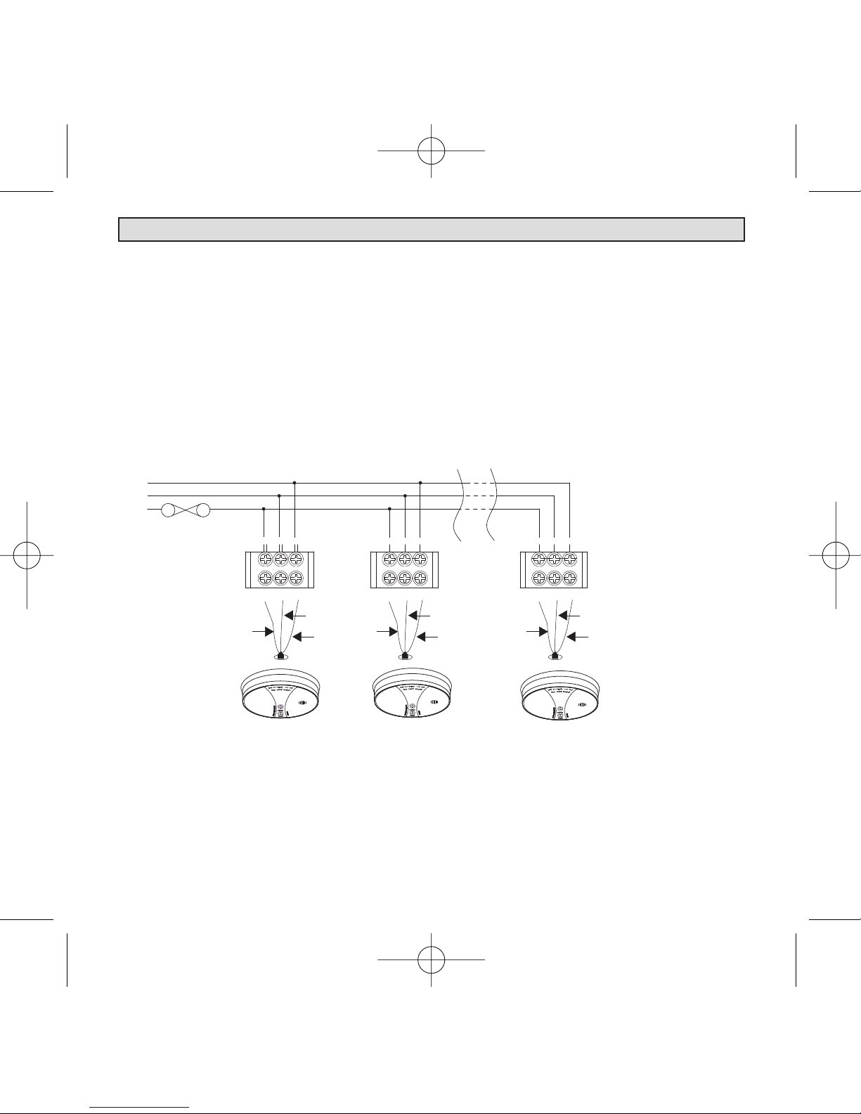
6.1.13 Terminals are marked as follows:
MARK NGS
(Red) A ACT VE
(White) S SW TCH W RE (FOR NTERCONNECT ON ONLY)
(Black) N NEUTRAL
WARN NG: Connecting the Switch wire terminal to any other supply
conductor may result in damage to the alarm, failure to operate or shock haz-
ard and void the warranty of the alarm.
7
6. I STALLATIO
1
N
sss
AN
AN
A
224
MAXIMUM OF 24 SMOKE ALMARMS
CONNECTION TO A
FUSE ON
CIRCUIT
BREAKER
ASN
RED
WHITE
BLACK
ASN
RED
WHITE
BLACK
ASN
RED
WHITE
BLACK
HOMEGUARD
INTERCONNECT
SMOKE
ALARM
HOMEGUARD
INTERCONNECT
SMOKE
ALARM
HOMEGUARD
INTERCONNECT
SMOKE
ALARM
1299-7201-01:_ 2014.5.7 10:40 AM Page 7

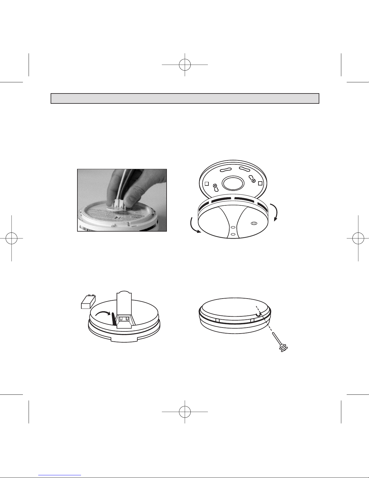
6.2.1 Pull the AC Quick-Connect wire harness through the centre hole in the
mounting plate and secure the plate, making sure that the mounting screws
are positioned in the small ends of the keyholes before tightening ( mage
1A).
6.2.2 Press the battery reminder tab down into the
battery compartment while inserting the battery
( mage 1D).
6.2.3 CAUTIO : f the battery reminder tab is not
held down in the battery compartment by the
battery, the battery door will not close and the
unit will not attach to the mounting plate.
6.2.4 Plug the AC Quick-Connect wire harness into
the back of the alarm ( mage 1B), making sure
that the locks on the connector snap into place.
Push the excess wire back into the electrical
box through the hole in the center of the
mounting plate.
8
6.2 Mounting Instructions:
6. I STALLATIO
6.1.14 When interconnected all Smoke Alarms will sound upon activation.
6.1.15 WAR I G: This alarm cannot be operated from power derived from a
square wave, modified square wave or modified sine wave inverter.
These type of inverters are sometimes used to supply power to the
structure in off grid installations, such as solar or wind derived power
sources. These power sources produce high peak voltages that will
damage the alarm.
6.1.16 PSA recommend the smoke alarms to be installed on its own subcircuit to
avoid false alarms and nuisance chirping that may be caused by electromag-
netic interferences from other electrical equipment.
IMAGE 1A
1299-7201-01:_ 2014.5.7 10:41 AM Page 8
9
6. I STALLATIO
6.2.5 Alignment marks are provided on the edge of the mounting plate and the
alarm. After installing the mounting plate, place the alarm onto the mounting
plate, making sure the alignment marks are lined up. Twist the alarm in the
direction indicated by the “ON” arrow on the alarm cover ( mage 1C) until it
locks in place.
OFF
ON
ROTATE TO MOUNT OR
TO REMOVE
BATTERY
REMINDER TAB
TAM ER-RESIST
LOCKING IN
SQUEEZE THE LOCKING IN OF
THE AC QUICK-CONNECT WIRE
HARNESS
IMAGE 1B IMAGE 1C
IMAGE 1D IMAGE 1E
1299-7201-01:_ 2014.5.7 10:41 AM Page 9

10
6. I STALLATIO
6.3 TEST & Battery Backup:
6.3.1 Homeguard model HG1000 will not function without a properly installed
battery. They are equipped with a battery lockout feature which prevents the
battery door from closing if a battery is not installed correctly (See Image
1D ).
6.3.2 To ensure proper operation of models with battery backup, press the Test
button for at least 5 seconds, or until the alarm sounds (without the AC
power connected). All interconnected, battery backed-up alarms, should
respond.
6.3.3 CAUTION: Due to the loudness (85 decibels) of the alarm, always stand an
arms-length away from the unit when testing.
6.3.4 Turn on the AC power. The green LED power indicator should be lit when the
alarm is operating from AC power.
6.3.5 Confirm unit operation by pressing the Test button again.
6.3.6 The smoke alarm is operating once AC power is applied, a fresh battery is
installed and testing is complete. When the smoke alarm ionization sensor cham-
ber senses products of combustion, the horn will sound a loud (85db) alarm until
the sensing chamber is cleared of smoke particles.
6.4 Alarm Tamper Resist Feature:
6.4.1 The smoke alarm is operating once AC power is applied, a fresh battery is
installed and testing is complete. When the smoke alarm ionisation sensor
chamber senses products of combustion, the horn will sound a loud (85db) alarm
until the sensing chamber is cleared of smoke particles.
OTE: The tamper-resistant pin will have to be removed in order to
change the battery . Use long nose pliers to pull the pin out of the hole.
It is now possible to remove the alarm from the mounting plate (See
Image 1E ).
1299-7201-01:_ 2014.5.7 10:41 AM Page 10

7. OPERATIO , TESTI G A D MAI TE A CE
7.1 Operation:
7.1.1 The smoke alarm is operational once all wires are properly connected, a fresh
battery is installed (HG1000), The smoke alarm is correctly installed on the
mounting base and the alarm has been tested.
7.1.2 There are two LED indicators. Each of them has a unique function:
7.1.3 Red LED
7.1.3.A Stand-by condition: will flash once approximately every 40 seconds to
indicate unit is functioning properly.
7.1.3.B Alarm condition: the Red LED will flash once every second.
For interconnected units, the originating smoke alarm Red LED will flash
once every second. All other units will sound but the Red LED will not be
on or flashing.
7.1.4 Green LED
7.1.4.A AC Mains-O Indicator: indicates that the unit is operating with AC
power. f this LED goes out, it indicates that the AC power is off.
7.2 False Alarm Hush Control Feature:
ote: Dense smoke will override Hush control feature and sound a
continuous alarm.
7.2.1 This smoke alarm has the capability of being temporarily desensitized for
approximately 5-15 minutes.
7.2.2 The smoke alarm is desensitized by pressing the“ Test / Hush ” button on
the smoke alarm cover.
7.2.3 After pressing the“ Test / Hush ” button, the alarm will silence immedi-
ately.
7.2.4 The smoke alarm will automatically reactivate after approximately 5-15
minutes and sound the alarm if particles of combustion are still present.
7.2.5 The “HUSH” feature may be used repeatedly until the air has cleaned.
WAR I G: Before using the alarm HUSH feature, identify the
source of smoke and be certain that a safe condition exists.
11
1299-7201-01:_ 2014.5.7 10:41 AM Page 11

12
7. OPERATIO , TESTI G A D MAI TE A CE
7.3 Operating and Alarm Characteristics.
Function LED Status Recommendation
Normal Green ON Green LED indicate the AC mains power
is present.
Normal Red FLASHING every
40 seconds.
Red LED flashes every 40 seconds is nor-
mal. The smoke alarm performs a self
test every 40 seconds. The battery and
electronics is tested for the life of the unit.
Alarm mode Red light flashing once
every second. Smoke
alarm activated.
Indicate smoke alarm has activated and is
in alarm mode.
Alarm mode Red Light is OFF. Smoke
alarm activated.
Smoke alarm in full alarm. Other intercon-
nected units may have activated the alarm.
Check other smoke alarms or devices.
Hush mode Green light ON. Red light
flashing every 10 sec-
onds and no chirp.
The “HUSH” feature has the capability of
temporarily desensitizing the alarm circuit for
approximately 8 minutes.
Low Battery Green ON, Flashing red
light every 40 seconds.
Smoke alarm chirp every 40 Seconds. May in-
dicate low battery status. Replace the battery.
1299-7201-01:_ 2014.5.7 10:41 AM Page 12

8. BATTERY I STALLATIO , REPLACEME TA D TEST
8.1 Battery Installation
8.1.1 The smoke alarm uses one 9V battery to automatically provide back-up
power to the alarm if AC power fails. The battery will operate the alarm for
approximately one to three months with AC power off.
8.1.2 The smoke alarm has a low battery indicator that will cause the unit to chirp
and flash the Red LED at approximately 40 second intervals for a minimum of 7
days. Missing battery with main power connected will cause the unit to chirp
and flash the Red LED at approximately 40 second intervals.
8.1.3 Replace battery when chirping occurs. To ensure proper operation, the bat-
tery should be replaced once a year.
8.1.4 To replace battery, remove alarm from mounting base(see section 6.2) and
remove the battery from compartment. Replace the old battery with a new one.
8.1.5 USE O LY THE FOLLOWI G 9 VOLT BATTERIES FOR
SMOKE ALARM REPLACEME T.
Carbon Zinc Type:GOLD PEAK 1604P
Alkaline Type: ENERG ZER 522; DURACELL MN1604, MX1604;
GOLD PEAK 1604A;
Lithium Type: ULTRAL FE U9VL-J
These batteries can be purchased at your local retail outlet or supermarket.
Caution: Use only specified batteries. Use of different battery may
have a detrimental effect on operation or may cause the battery to
explode resulting in injury or fire.
13
1299-7201-01:_ 2014.5.7 10:41 AM Page 13

14
8. BATTERY I STALLATIO , REPLACEME TA D TEST
8.1.6 USE O LY BATTERIES SPECIFIED O THE LABEL .
8.1.7 Fold Red Battery Lever down into compartment with fresh replacement
battery. f the Red Battery Lever is not held down in the battery compart-
ment by the battery, the smoke alarm will not close and will not be opera-
tional. Battery can only be inserted in one direction, ensure polarity is correct.
WAR I G: Use of inferior batteries or incorrect types may cause a malfunction of the
alarm. When replacing the battery and on reconnection of the detector to the base plate,
make sure that the detector is fully connected and flush with the base plate. Verify that
the Green LED is O after reinstalling the alarm on the base plate.
8.2 Battery Test:
8.2.1 Switch off mains power. The Green LED on the smoke alarm will be OFF.
8.2.2 Test alarm by pressing on the Test Button for a few seconds. This should sound the alarm.
8.2.3 f the battery module has a fault, the alarm will chirp every 40 seconds.
8.2.4 Watch the Red LED for about 40 seconds. t should flash at least once.
8.2.5 Switch on mains power only when smoke alarm passes the above tests. The Green
LED on the smoke alarm will come ON.
OTE: WEEKLY TESTI G IS RECOMME DED!
1299-7201-01:_ 2014.5.7 10:41 AM Page 14

9. REPAIRS A D SERVICES
9.1 f the smoke alarm is defective in any way, do not tamper with the unit. Re-
turn the unit to your supplier (See warranty for instructions on in-warranty
returns). There will be a service charge for repairing units out of warranty.
WAR I G: DO OT TAMPER WITH RADIOACTIVE SOURCE
The use of this product should not be seen as a substitute for basic safety precau-
tion in the prevention of FIRE.
There are situations where a smoke alarm may not be effective to protect against fire:
10.1 smoking in bed;
10.2 leaving children home alone;
10.3 cleaning with flammable liquids, such as petrol.
11. THE LIMITATIO S OF SMOKE ALARMS
11.1 Smoke alarms are devices that can provide early warning of possible devel-
oping fires at a reasonable cost.
11.2 Alarms have sensing limitations. onisation sensing alarm may detect invisi-
ble fire particles (associated with fast flaming fires) sooner than Photo-elec-
tric alarms. Photo-electric sensing alarm may detect visible fire particles
(associated with slow flaming fires) sooner than onisation alarms. Home
fires develop in different ways and are often unpredictable. Neither type of
alarm (photo-electric/ionisation) is always best and a given alarm may not
always provide warning of a fire.We strongly recommend that both ionisation
and photoelectric smoke alarms be installed to help insure maximum detection of
the various types of fires that can occur within the home.
11.3 Smoke alarms have certain limitations. For battery powered smoke alarms,
the battery must be in good condition and installed properly.
11.4 AC powered alarms will not operate if AC power has been cut off, such as by
an electrical fault, open fuse or circuit-breaker, or fire. However, the battery
back-up will activate the alarm if in good working order.
10. GOOD SAFETY HABITS
15
1299-7201-01:_ 2014.5.7 10:41 AM Page 15

16
11.5 Smoke alarms must be tested regularly to ensure that the batteries and alarm
circuit are in good operating condition.
11.6 Smoke alarms cannot provide an alarm if smoke does not reach the alarm.
Therefore, smoke alarm may not sense fires starting in chimneys, walls, on
roofs, on the other side of a closed door, or on a different floor.
11.7 f the alarm is located outside the bedrooms, or on a different floor, it may
not wake up a sound sleeper. A smoke alarm in the bedroom, therefore, is
recommended.
11.8 Smoke alarms have been significant in saving lives in many parts of the
world. Hence, the use of this product does not substitute for basic prevention
and total protection.
11.9 Although smoke alarms can help save lives by providing early warnings of a
fire, they are not a substitute for an insurance policy.
11.10 This smoke alarm alone will not alert the hearing impaired. Use special
purpose smoke alarm with lights or vibrating devices, for those hard of hearing.
11.11 Heat alarms are available to offer greater security when used in conjunction
with smoke alarms.
11.12 Life safety from fire in residential occupancies is based primarily on early
notification to occupants of the need to escape, followed by the appropriate
egress actions by those occupants. Fire warning systems for dwelling units
are capable of protecting about half of the occupants in potentially fatal
fires. Victims are often intimate with the fire, too old or young, or physically
or mentally impaired such that they cannot escape even when warned early
enough that escape should be possible. For these people, other strategies such
as protection-in-place or assisted escape or rescue are necessary.
11. THE LIMITATIO S OF SMOKE ALARMS
1299-7201-01:_ 2014.5.7 10:41 AM Page 16

17
12. OPERATI G PRI CIPLES OF SMOKE ALARMS
IO ISATIO CHAMBER:
A man-made radio-active element, Americium 241 is used in this design. This element
ionises the air round it and as a result, excellent conductivity is possible refer to illus-
tration showing ‘Clear Air’). Current supplied by either the mains power (where appli-
cable), or the battery would pass through the gap with ease without causing any alarm.
However, in the event of particles arising from combustion or dust particles (refer il-
lustration showing ‘Smoke’) entering the Sensing Chamber, it encapsulates the ionised
air. This interaction causes an increased resistance to conductivity. When this occurs,
the alarm is activated.
Ionisation type smoke alarm is best for detecting flaming fires.
1299-7201-01:_ 2014.5.7 10:41 AM Page 17

18
PHOTOELECTRIC CHAMBER:
A light transmission source and a photosensitive receiver is used in this design. Light
that is transmitted fall upon the receiver. When smoke or dust enters the light path,
some of the light is scattered or absorbed. The result of a reduction of light falling
upon the photosensitive receiver will cause an alarm.
Photoelectric smoke alarm is best for detecting smouldering fires.
13. DEVELOP A D PRACTICE A PLA OF ESCAPE
12. OPERATI G PRI CIPLES OF SMOKE ALARMS
BASIC OF ESCAPE PLA :
13.1 Make a floor plan indicating all doors and windows and at least two escape
routes from each room. Second storey windows may need a rope or chain
ladder.
13.2 Have a family meeting and discuss your escape plan, showing everyone what
to do in case of fire.
13.3 Determine a place outside your home where all of you can meet, if a fire oc-
curs.
13.4 Familiarize everyone with the sound of the smoke alarm and practice leaving
your home when they hear it.
1299-7201-01:_ 2014.5.7 10:41 AM Page 18
Table of contents
Other PSA Products Smoke Alarm manuals


