Carrier Debonair 33CS250-RC Instructions and recipes

Installation, Start-Up, and
Operating Instructions
Part Number 33CS250-RC
CONTENTS Page
SAFETY CONSIDERATIONS ...................1
GENERAL ...................................1
INSTALLATION .............................1-5
Install Batteries ..............................1
Select Transmitter Location (Optional) ........1
Mount Transmitter (Optional) .................2
Set Clock ....................................2
Configure Advanced Set Up ..................2
Program Thermostat Schedules ...............3
Calibration ...................................5
Check Thermostat Operation .................5
Final Checklist ...............................5
OPERATION ................................5,6
Auto-Changeover ............................5
Two-Stage Operation .........................5
Fan Operation ...............................5
Electric Heat .................................5
Keypad Lock ................................5
Unit ID Number ..............................5
Dry Contact Switch/External Control ..........6
TROUBLESHOOTING .........................6
IMPORTANT: Read entire instructions before starting the
installation. Leave installation instructions with owner af-
ter performing installation.
SAFETY CONSIDERATIONS
Read and follow manufacturer instructions carefully. Fol-
low all local electrical codes during installation. All wiring
must conform to local and national electrical codes. Im-
proper wiring or installation may damage thermostat.
Recognize safety information. This is the safety alert sym-
bol . When the safety alert symbol is present on equip-
ment or in the instruction manual, be alert to the potential
for personal injury.
Understand the signal words DANGER, WARNING, and
CAUTION. These words are used with the safety alert sym-
bol. DANGER identifies the most serious hazards which will
result in severe personal injury or death. WARNING signi-
fies a hazard which could result in personal injury or death.
CAUTION is used to identify unsafe practices which would
result in minor personal injury or property damage.
GENERAL
The wireless, 7-day, commercial, programmable ther-
mostats maintain room temperature by controlling the
operation of an HVAC (heating, ventilation, and air condi-
tioning) system. Separate heating and cooling set points and
auto-changeover capability allow programming of 4 differ-
ent time periods for energy savings.
All thermostats allow up to 4 time/temperature settings to
be programmed per 24-hr period. Each thermostat stores pro-
grams for 7 independent days. Batteries are required for op-
eration. During power interruption (batteries removed) the
internal memory stores configuration and comfort schedules
for an unlimited time. The clock will need to be reset
everytime power is lost (batteries changed).
The wall mounted or hand-held transmitter sends its sig-
nal to a receiver installed near the HVAC unit. Each trans-
mitter and receiver can be given a separate house code for
multiple thermostat applications. Up to 4 transmitters can
send information to one receiver device.
The thermostat can be configured to accept several
different equipment configurations, including heat pump
operation.
IMPORTANT: The transmitter and receiver are factory con-
figured with a house code of 0. If more than one set of
wireless transmitters and receivers are used in the same
location, the house codes must be different for the ther-
mostats to communicate properly.
INSTALLATION
Install Batteries — Two AA lithium batteries are in-
cluded with the transmitter. Remove the back cover and in-
stall batteries. To ensure proper operation, only useAAlithium
batteries as replacements.
Select Transmitter Location (Optional) — The
transmitter is wireless and no mounting or wiring of the trans-
mitter is required. However, if a mounting location is de-
sired for the transmitter, the transmitter should be mounted:
• approximately 5 ft from the floor
• close to or in a frequently used room, preferably on an
inside partitioning wall
• on a section of wall without pipes or ductwork
• where temperature operating limits are within 41 to 104 F
(5 to 40 C)
• where humidity operating range is within 0 to 95% rela-
tive humidity, non-condensing
The thermostat should NOT be mounted:
• close to a window, on an outside wall, or next to a door
leading to the outside
• where exposed to direct light and heat from a lamp, the
sun, a fireplace, or any other temperature-radiating object
which may cause a false reading
Debonair™
Commercial Programmable Thermostat
Wireless Transmitter
Manufacturer reserves the right to discontinue, or change at any time, specifications or designs without notice and without incurring obligations.
Book 1 4
Tab 11a 13a PC 111 Catalog No. 533-322 Printed in U.S.A. Form 33CS-16SI Pg 1 11-98 Replaces: New

• close to or in direct airflow from supply registers or return
air grilles
• in areas with poor air circulation (such as behind a door or
in an alcove)
Mount Transmitter (Optional)
IMPORTANT: If the transmitter is replacing an existing
thermostat and will be mounted in the same location, the
wiring from the unit must be run to a different location
where the receiver is mounted. The transmitter is NOT wired
to the unit. The receiver is wired to the unit and processes
the signals received from the transmitter.
1. If an existing thermostat is being replaced:
a. Remove existing thermostat from the wall.
b. Disconnect wires from existing thermostat. Remove
wiring.
c. Discard or recycle old thermostat.
NOTE: Mercury is a hazardous waste and must be
disposed of properly.
2. Remove the transmitter cover from wall plate (mount-
ing base) to expose mounting holes. See Fig. 1.
3. Level mounting base against wall and mark wall through
the 2 mounting holes in base.
4. Drill two
3
⁄
16
-in. mounting holes in wall where marked.
Be careful not to drill into wiring in wall. Electri-
cal shock could result.
5. Secure mounting base to wall with 2 screws and an-
chors provided.
6. Seal hole in wall to prevent drafts.
7. Re-attach transmitter cover to back plate.
Set Clock — The user can change the time and day dis-
played on the transmitter. Press and hold the Mode and Over-
ride buttons simultaneously for at least 2 seconds. The trans-
mitter will be in Set Clock mode. The display will show the
Set Up annunciator. The number of the Set Up step is shown
in the upper right corner. The current time will blink on and
off. Current Time is Set Up Step 1. Press the UP ARROW
and DOWNARROW buttons until the correct time is shown.
Hold down the buttons to quickly move through the time
display. The AM and PM annunciators will automatically
change. To ensure the schedules are properly followed, make
sure that AM or PM is correct for the time chosen. Hold
down the Override button while pressing the UP or DOWN
ARROW buttons to scroll through by hours instead of min-
utes. When the correct time is shown, press the Mode button
to modify the day of the week. The current day will blink on
and off. The Day of the Week is Set Up Step 2. Press the UP
ARROW and DOWNARROW buttons until the correct day
is shown. Press and hold the Mode and Override buttons again
for 2 seconds to exit the Set Clock mode. If no button is
pressed for 60 seconds, the display will automatically return
to normal operation.
ConfigureAdvanced Set Up — To enter into the ad-
vanced set up screens of the transmitter, press and hold the
Mode and Override buttons for at least 5 seconds. The set up
step number is shown in the top right corner of the trans-
mitter screen. Use the Mode button to advance through the
steps. See Table 1. Press the Mode and Override buttons at
the same time to exit the Advanced Set Up mode. If no but-
ton is pressed for 60 seconds, the display will automatically
return to normal operation.
NOTE: See Set Clock section above for information on Ad-
vanced Set Up steps 1 and 2.
ZONING SYSTEM (Step 3) — The Zoning System con-
figuration configures the thermostat for use in a zoning sys-
tem. If the thermostat is being used in a zoning system, set
the configuration to YES. If the thermostat is not being used
in zoning system, set the configuration to NO. The default
is NO.
HOUSE CODE (Step 4) — The house code is used by the
transmitter and receiver to identify that they are used to-
gether. If more than one transmitter is used, all transmitters
must have the same house code number as the receiver. If
separate receivers and transmitters for different equipment
are used near each other, they should be configured with dif-
ferent house codes. The default is 0. The range is 0 to 63.
NOTE: More than one receiver can be used on jobs where
the furnace and air conditioner are not wired together. Two
separate receivers can be used with one wired to the furnace
and one wired to the air conditioner, which can both be con-
trolled by the same transmitter. These receivers must have
the same house code.
UNIT ID NUMBER (Step 5) — The unit ID number is used
when more than one transmitter is used with a receiver. When
more than one transmitter is used with a receiver, each trans-
mitter must be given a different unit ID number. This allows
the receiver to keep track of which transmitter sent the last
command. This transmitter will control the unit until a dif-
ferent transmitter sends a command to the receiver. The de-
fault is 1. The range is 1 to 4.
NOTE: Advanced Configuration steps 6, 7, 9, 11 are
only available for transmitters configured with Unit ID Num-
ber 1.
FAN MODE (Step 6) — The fan mode is used to configure
fan operation. If Fan On is selected, the fan will run con-
tinuously during the Occupied schedule (except when Mode
is switched to OFF). The fan will be off during unoccupied
schedule except during heating or cooling operation.
If Auto is selected, the fan will operate only during heat-
ing or cooling operation. The default is Auto.
DEADBAND (Step 7) — The Deadband is the difference in
temperature above the cooling set point or below the heating
set point that the thermostat will wait before turning on the
first stage of heating or cooling. For example, if the cooling
set point is 82 F and the deadband is 2 degrees F, the first
stage of cooling will not be energized until the temperature
reaches 84 F. The range of values is 1 to 6 degrees. The de-
fault is 2.
MOUNTING
HOLES
Fig.1—Transmitter Backplate
2

SET POINTMINIMUM DIFFERENCE (Step 8) —The mini-
mum difference between heating and cooling set points can
be user-configured. The range is from 0 to 6 degrees. The
default is 2. The minimum difference is enforced during Auto-
changeover and Program On operation.
CYCLES PER HOUR LIMIT (Step 9) — The number of
times that heating or cooling can be energized per hour can
be configured. Set the variable to ‘‘d’’ for no limit. Set the
variable to ‘‘d1’’ to disable the 5-minute compressor lock-
out. The variable can also be set from 2 to 6 cycles per hour.
The default is 6.
The ‘‘d1’’ configuration is used for service and trouble-
shooting procedures only. Do not use for normal
operation. Damage to air-conditioning equipment may
result.
BACKLIGHT DISPLAY (Step 10) — The display backlight
can be set to ON (always on) or OFF (turn off 8 seconds
after last button pressed). The default is ON.
NOTE: The transmitter display backlight can only be set to
ON (always on) if a dedicated power source is connected to
the transmitter. If the transmitter is using batteries, the con-
figuration cannot be set to ON.
PRE-OCCUPANCY PURGE TIMER (Step 11) — The pre-
occupancy purge allows fresh outside air to be brought into
the space before the Occupied 1 time period. The timer lim-
its the amount of time that the purge can operate. The timer
can be set from 0 to 3 hours with 15-minute intervals. The
default is 0 hours (disabled).
FAHRENHEIT/CELSIUS OPERATION (Step 12) — The
transmitter can be set to operate in Fahrenheit or Celsius de-
grees. Set the variable to ‘‘F’’ for Fahrenheit operation. Set
the variable to ‘‘C’’for Celsius operation. The default is ‘‘F.’’
SECURITY LEVEL (Steps 13 to 15) — The Security Level
limits the actions that the user can perform at the transmitter.
There are 4 security levels. When the security level is set to
‘‘0,’’ no security will be in effect. When the security level is
set to ‘‘1,’’ the set point range is limited by the settings of
Steps 14 and 15. When the security level is set to ‘‘2,’’ the
set point range is limited by the settings of Steps 14 and 15
and the Program On mode is always in effect. When the se-
curity level is set to ‘‘3,’’the set point range is limited by the
settings of Steps 14 and 15, the Program On mode is always
in effect, and set point changes are prohibited. The default
is 0.
Security Maximum Heat Set Point (Step 14) — If the Se-
curity Level is not set to 0, the maximum heating set point
will be in effect. The user will not be allowed to set the heat-
ing set point over the specified value. The range of values is
35 to 99 F (1 to 37 C). The default is 80 F (27 C).
Security Minimum Cool Set Point (Step 15) — If the Se-
curity Level is not set to 0, the minimum cooling set point
will be in effect. The user will not be allowed to set the cool-
ing set point below the specified value. The range of values
is 35 to 99 F (1 to 37 C). The default is 65 F (18 C).
Program Thermostat Schedules — Before pro-
gramming the thermostat, plan the thermostat daily sched-
ule. The schedule is divided into 7 days (Monday through
Sunday). Each day has from 2 to 4 time periods (Occupied
1, Occupied 2, Occupied 3, Unoccupied) depending on the
configuration of the thermostat. Each occupied time period
has a start time, stop time, heating set point, and cooling set
point. The unoccupied time period has a heating set point
and a cooling set point. The unoccupied time period is active
when ever an occupied time period is not active. Fill in
Table 2 as an aid to programming the daily schedules.
Table 1 — Advanced Set Up Configuration
STEP DESCRIPTION RANGE DEFAULT
1Time of Day 12:00 AM - 11:59 PM 12:00 AM
2Day of the Week Sunday through Saturday Monday
3Zoning System No/Yes No
4House Code 0 - 63 0
5Unit ID Number 1 - 4 1
6* Fan Mode Auto/Fan On Auto
7* Deadband 1 - 6 degrees 2
8Forced Minimum Temperature Difference 0 - 6 degrees 2
9* Cycles per Hour d, d1,2-6 6
10 Thermoglow™ Backlight Off/On On
11* Fan Purge Timer 0:00 - 3:00 0:00
12 Temperature Units F/C F
13 Security Level 0 - 3 0
14 Maximum Allowable Heat Set Point 35 - 99 F (1 - 37 C) 80 F (27 C)
15 Minimum Allowable Cooling Set Point 35 - 99 F (1 - 37 C) 65 F (18 C)
*Only available on transmitter with Unit ID Number configured to 1.
3

Table 2 — Daily Schedule Planner
DAY
OF THE
WEEK
SCHEDULE
Occupied 1 Occupied 2 Occupied 3 Unoccupied
Start / Stop / Heat / Cool Start / Stop / Heat / Cool Start / Stop / Heat / Cool Heat / Cool
Monday /// /// /// /
Tuesday /// /// /// /
Wednesday /// /// /// /
Thursday /// /// /// /
Friday /// /// /// /
Saturday /// /// /// /
Sunday /// /// /// /
NOTE: The cooling temperature set point must be higher than the heating temperature set point. (The temperature difference may be changed in the advanced set up
configuration.)
PROGRAMMING MODE — To program the daily sched-
ules, perform the following procedure:
1. Enter programming mode by pressing and holding the
Mode and UP ARROW buttons for 2 seconds. The Oc-
cupied 1 annunciator will appear on the thermostat dis-
play. Use the UP ARROW and DOWN ARROW but-
tons to set the maximum number of Occupied periods
for each day. The thermostat can be set to 1, 2, or 3.
After the number of Occupied periods has been se-
lected, press the Mode button. See Fig. 2.
2. The cooling set point for Occupied 1 will be displayed.
Use the UP ARROW and DOWN ARROW buttons to
raise or lower the cooling set point until the desired tem-
perature is shown. The range of acceptable values is 35
to 99 F (1 to 37 C). Press the Mode button to continue.
See Fig. 2.
3. The heating set point for Occupied 1 will be displayed.
Use the UP ARROW and DOWN ARROW buttons to
raise or lower the heating set point until the desired tem-
perature is shown. The range of acceptable values is 35
to 99 F (1 to 37 C). Press the Mode button to continue.
See Fig. 2.
4. The cooling set point for Unoccupied will be displayed.
Use the UP ARROW and DOWN ARROW buttons to
raise or lower the cooling set point until the desired tem-
perature is shown. The range of acceptable values is 35
to 99 F (1 to 37 C) or ‘‘OF’’ (no unoccupied cooling).
Press the Mode button to continue.
5. The heating set point for Unoccupied will be displayed.
Use the UP ARROW and DOWN ARROW buttons to
raise or lower the heating set point until the desired tem-
perature is shown. The range of acceptable values is 35
to 99 F (1 to 37 C) or ‘‘OF’’ (no unoccupied heating).
Press the Mode button to continue.
6. The day of the week will be shown. Use the UP AR-
ROW and DOWN ARROW buttons to change the day
of the week until the desired starting day is shown. Pos-
sible choices are M (Monday) through S (Sunday). Press
the Mode button when the desired day is shown.
7. The Start Time for Occupied 1 will be displayed. Use
the UP ARROW and DOWN ARROW buttons to raise
or lower the time until the desired Start Time is shown.
Press the Mode button to continue. See Fig. 3.
8. The Stop Time for Occupied 1 will be displayed. Use
the UP ARROW and DOWN ARROW buttons to raise
or lower the time until the desired Stop Time is shown.
Press the Mode button to continue.
9. The On/Off icon will be displayed. Use the UP AR-
ROW to turn the Occupied 1 period ON for this day.
Use the DOWN ARROW to turn the Occupied 1 period
OFF for this day.
10. Repeat Steps 2 through 9 to program the remaining sched-
ule for Occupied periods 2 and 3.
11. The Copy command can be used to copy the previous
day’s schedule if the schedules are the same. The copy
command becomes available after all the occupied pe-
riods are programmed in a day. Use the UP ARROW to
change the copy command toYES. Use the DOWNAR-
ROW to change the copy command to NO. Press the
Mode button when the choice has been made. See
Fig. 4.
If NO was selected, the schedule will automatically change
to the next day and the user must enter the occupied and
unoccupied schedules for that day.
Fig. 2 — Setting Occupied 1 Set Points
Fig. 3 — Start Time Display
4

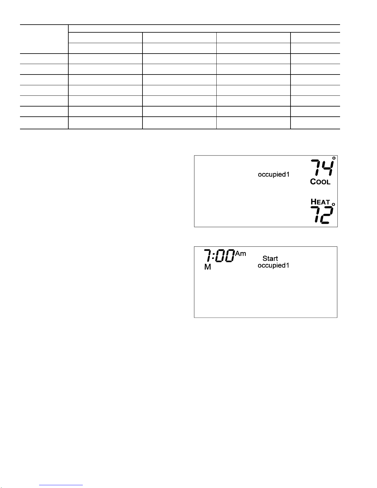
NOTE: Occupied 1 schedule heating and cooling set points
are the same for each day. Occupied 2 and 3 set points
may be set to different values for each day of the week.
If YES was selected, the schedule will be copied to the
next day. The schedule copy may be repeated until Sun-
day is reached. The Sunday schedule cannot be copied
to Monday.
12. After all the times and set points for each day have been
entered, press and hold the Mode and UPARROW but-
tons for 2 seconds to exit Programming mode.
NOTE: The thermostat will continue to follow the schedule
until a new one is entered.
If only one occupied schedule is selected, the Occupied 2
and 3 schedules are skipped. If the start time is set later in
the day than the stop time, the program will run from mid-
night of that day to the stop time and then from the start time
to midnight. If the same start and stop times are pro-
grammed for an occupancy schedule, the thermostat will be
in Occupied mode for 24 hours. If one occupied period starts
or stops within another occupied period, the lower num-
bered schedule has priority. For example, if schedule Oc-
cupied 3 is running for 24 hours and Occupied 2 schedule
comes on from 1 to 3 PM, the set points from Occupied 2
are in effect from 1 to 3 PM.
OVERRIDING THE SCHEDULE — The schedule can be
overridden by pressing the UP or DOWN ARROW buttons
to change the desired temperature. The thermostat will use
the new set point until the next scheduled time period starts.
Calibration — Every transmitter temperature sensor is
factory calibrated. Under normal circumstances there will never
be a need to re-calibrate the sensor. If re-calibration must be
done, perform the following procedure:
1. Hold down the Mode button and press the DOWN
ARROW button simultaneously for 2 seconds. All of the
icons on the display screen will appear. Release the
buttons.
2. Press the Mode button. The current temperature will be
displayed.
3. Use an accurate thermometer to measure room tempera-
ture. Press the UP or DOWN ARROW buttons until the
displayed temperature equals room temperature.
4. Press the Mode button to return to normal operation.
Check Thermostat Operation — To check thermo-
stat operation, perform the following procedure:
1. Press the Mode button repeatedly until the Heat icon ap-
pears on the display. The thermostat is now in Heating
mode.
2. Press the UP ARROW button until the heating set point
is 10 F (6 C) higher than the current room temperature.
Heating and fan should be energized.
3. Press the Mode button repeatedly until the Cool icon ap-
pears on the display. The thermostat is now in Cooling
mode.
4. Press the DOWN ARROW button until the cooling set
point is 10 F lower than the current room temperature.
Cooling and fan should be energized.
5. If heating, cooling, or fan operations do not energize, check
wiring and consult Troubleshooting section.
Final Checklist
1. Put away tools and instruments. Clean up debris and
packaging.
2. Review Owner’s Guide with occupant or owner.
3. Leave the manuals with owner.
OPERATION
The Mode button selects the operating mode of the ther-
mostat. If OFF is selected, the thermostat will not enter Heat-
ing or Cooling mode. If HEAT is selected, the thermostat
will only enter Heating mode (if the room temperature is
below the heating set point). If COOL is selected, the ther-
mostat will only enter Cooling mode (if the room tempera-
ture is above the cooling set point). If AUTO is selected, the
thermostat will enter Heating or Cooling mode based on the
room temperature and the heating and cooling set points. If
PROGRAM ON is selected, the stored schedule is enabled
and the thermostat will follow the time period schedules stored
in its memory.
NOTE: The transmitter must be configured to Unit ID Num-
ber 1 to have a programmed schedule.
Auto-Changeover — When the thermostat mode is set
to AUTO or PROGRAM ON, the thermostat will provide
automatic changeover from Heating to Cooling mode and
Cooling to Heating mode when required. The thermostat will
automatically switch to maintain the desired temperature set-
ting. The thermostat does not need to be manually changed
from heating to cooling or cooling to heating operation.
Two-Stage Operation — The second stage of heat or
cool is turned on when the first stage has been on for a mini-
mum of 2 minutes and the temperature differential from the
set point is equal to or greater than the set point plus the
deadband plus 2 degrees.
Fan Operation — If Fan On is selected, the fan will run
continuously during occupied schedule (except when Mode
is switched to OFF). The fan will be off during unoccupied
schedule except during heating or cooling operation.
If Fan On is not selected, the fan will only operate during
heating or cooling operation.
Electric Heat — When the Electric Heat DIP switch on
the receiver is set to ON, the thermostat will turn on the fan
immediately any time there is a heat demand. This feature
should only be used on electric heating applications. Do not
use with gas heat.
KeypadLock — To prevent unauthorized use of the ther-
mostat, the front panel buttons can be disabled. To disable or
lock the keypad, press and hold the Mode button. While hold-
ing down the Mode button, press the UP and DOWN
ARROW buttons simultaneously. The ‘‘Locked’’ icon will
appear on the display.
The thermostat is unlocked by performing the same pro-
cedure. Press and hold the Mode button. While holding down
the Mode button, press the UP and DOWN ARROWbuttons
simultaneously. The ‘‘Locked’’ icon will be removed from
the display.
Unit ID Number — If more than one transmitter (up to
4) is used with a single receiver, the transmitters must be
given different Unit ID Numbers. Only the transmitter with
Unit ID Number 1 may have a programmed schedule or be
fig. 4 — Copy Command Display
5

configured. All configuration parameters are taken from the
transmitter with Unit ID Number 1. Transmitters with Unit
ID Numbers 2, 3, and 4 cannot be programmed or config-
ured (except for set points).
When more than one transmitter is used, the receiver will
only accept commands from the transmitter that was last used
(button pressed). All other set points and modes from other
transmitters are ignored. If the transmitter with Unit ID Num-
ber 1 has a schedule and is in Program On mode, the re-
ceiver will revert back to following the programmed sched-
ule when a time period change occurs, even if the trans-
mitter with Unit ID number 1 is not the current commanding
transmitter.
DryContact Switch/External Control — A dry con-
tact switch is provided to allow an external device to force
the thermostat into Unoccupied mode. This occurs at the re-
ceiver and is not shown on the transmitter. The external de-
vice is wired to contacts CK1 and CK2. See Fig. 5.
CK1
CK2
CK1
CK2
CK1
CK2
EXTERNAL
DEVICE RECEIVER RECEIVER RECEIVER
NOTE: Do not cross wiring.
Fig. 5 — Dry Contact Switch Wiring
6

TROUBLESHOOTING
PROBLEM SOLUTION
Display on transmitter not
illuminated. Check battery.
Cooling will not energize. Select COOL mode. Decrease cooling set point to 10 degrees below
room temperature. Check for 24 vac at Y1 terminal on receiver. If
present, thermostat is operating correctly and problem is with receiver
wiring or equipment. If 24 vac is not present, replace the thermostat.
Check for Compressor Cycle per Hour Limit. Cooling may be locked out.
Heating will not energize. Select HEAT mode. Increase heating set point to 10 degrees above room
temperature. Check for 24 vac at W1/O/B terminal on receiver. If present,
thermostat is operating correctly and problem is with receiver wiring or
equipment. If 24 vac is not present, replace the thermostat.
When using 4 wires (R,G,W,Y) connected to receiver,
the air conditioning equipment tries repeatedly to turn
on, but cannot.
There is not enough power available. Connect a 270 ohm, 10 watt power
resistor at the air conditioning equipment between terminals W and C on
receiver.
When controlling a heat pump, heat comes on during
cooling cycle. Configure receiver for heat pump operation. (See wireless receiver
installation instructions.)
When calling for cooling, both heating and cooling are
energized. The receiver is configured for a heat pump. Configure the receiver for
non-heat pump operation. (See wireless receiver installation instructions.)
When controlling a commercial heat pump unit, unit
runs in reverse or heating is always on. Some commercial heat pumps require that Heat Pump option (DIP switch
on receiver) is turned OFF. Check the unit installation instructions for
more information.
7

Copyright 1998 Carrier Corporation
Manufacturer reserves the right to discontinue, or change at any time, specifications or designs without notice and without incurring obligations.
Book 1 4
Tab 11a 13a PC 111 Catalog No. 533-322 Printed in U.S.A. Form 33CS-16SI Pg 8 11-98 Replaces: New
Table of contents
Other Carrier Transmitter manuals
Popular Transmitter manuals by other brands

E+E Elektronik
E+E Elektronik EE310 Operation manual

Extron electronics
Extron electronics XTP T EU 202 Setup guide

Visonic
Visonic MCT-211 installation instructions

Bühler technologies
Bühler technologies Pressotronik 700 Brief instructions

Traxxas
Traxxas DR-1 operating instructions

gofanco
gofanco PRO-FiberIP Series user guide