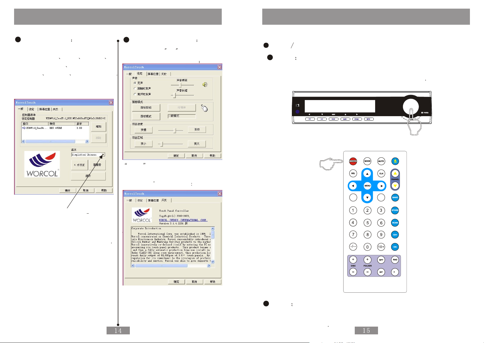
Operation of the Monitor
Monitor will Display the Hint of
Being OFF of PC by Pressing the
PC PWR then Press the PC PWR again
the PC will be Closed
Reset Control of Car PC
Connect the Reset Control Cable
of Car PC which is with the High Level
Reset Function
The Hint of Monitor will be Displayed by
Pressing the RST of the Front Case needed
Requirement then Press the RST again to
Reset the Car PC
ON OFF Control of Car PC
Connect the Control Cable of Car PC
with High Level 3 for Opening and
Low Level for Closing
Correctly according to the Requirement
Such as the Device Connect Drawing
Attached at the End
Monitor will Display the Hint of
being on of PC by Pressing the
PC PWR Key then High Level will be
Inputted by Control Cable of PC ON
to Control the PC ON or no Any Action
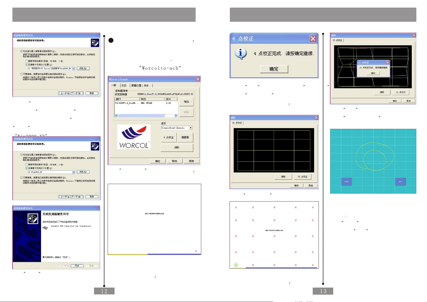
Operation of the Touch panel
Installation of the CD Drive
Start the Car PC after the Confirmation
of the Correct Connection Install the
Drive of the Touch Panel if it can Run
Natural Take WINDOWS XP an Example to
Introduce the Installation
The PC will Display the New USB Device
when Starting .
Pls Choose Cancel
Put the Attached CD Drive into the
DVD ROM of the PC If DVD ROM Set the
Function of Auto Fun it is as Follows
Cautions
If DVD ROM Has no Auto Fun Function
Double Clink the RUN EXE Files
in the Root Directory of the CD Drive
then the Windos also will be As Above
The Touch Panel is Used for Car PC
without any other Function to
Control the Machine
Users should connect the Touch panel
Control with USB cable of Car PC
Correctly and Install the right
Drive well befor Using the
Touch Panel Function
Users should Calibrate and Set
before Using Touch Panel Function
Users should Calibrate and Set
again after Using some Time
Normally Such as half a Month
or any Warp for the Touch Panel
with Image
Please Calibrate every Half a
Months to Make Sure the Warp
is within the Allowable Range
Following Installation and Calibration
of CD Drive of touch panel is
The CD Drive Soft of other Section
will be Some Difference for
Installation and Calibration
Please be Patient to Install
Corresponding Section to Install
and Calibrate
Don t Touch the Panel Directly by
Hard Thing or Nail to Avoid the Scrape
of the Panel
Operate the Machine by being
Attached Touch Pen
Clean the Touch Pane by Soft
Cloth to Avoid the Scrape of
the Pane Don t Clean the Touch
Panel by Organic Impregnant
to Avoid Damage of ITO Film
to Effect the Cuphotic Ratio of the
Touch Panel