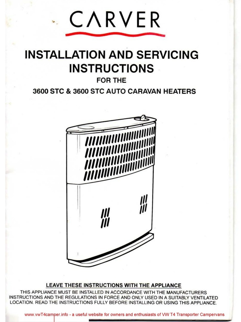
Carver Fanmaster User manual

CARVER
FANMASTER
WARM
AIRFANHEATER
INSTALLATIONINSTRUCTIONS
PLEASE
LEAVETHESEINSTRUCTIONSWITHTHE
APPLIANCE
www.vwT4camper.info - a useful website for owners and enthusiasts of VW T4 Transporter Campervans

1-GENERAL
DESCRIPTION
TheFanmasterisanautomaticallycontrolledfandesignedtodistributewarmair
throughducts,tooutletspositionedaroundthecaravan.
TheFanmasterisdesignedtofitontothebackoftheinstallationboxofanyCarver
1800,
2000or3000heaterandtheairmaybeheatedeitherbytheCarverheater
orbytheFanmaster'sownintegralelectricelements.butnotby
both
simultaneously.
TheintegralelementsareautomaticallyormanuallyswitchablebetweenOkW,
1
<Wand2kW.Theyrequirea 230vACmainssupplyand
will
drawapproximately
8ampsat2kW.
Tr.efanandtheelectroniccontrolrequirea 12vDCsupplyand
will
draw
aooi-oximately1.5Aat
full
speed.
All
functionsoftheFanmasterarecontrolledbya remote,wallmounted,controller.
This
controllerdoesnotcontaina thermostatsensorsoitcanbemountedinany
convenientposition.
2-
Specification
2.1HeatingElementSupply:
2.2FanandControlSupply:
2.3AirDelivery:
230vAC,8.1amp,1863W
Fused
at10- 13amp.
12vDC,1.5amp,18W
Fused
at5 amp.
100m3/hmaximum.
2.4Weight3.05Kg
2.5SafetyFeatures:A thermistorinthefan,sensingairtemperatureand
controllingtheelementpowerandfan
speed.
An
overtemperature,manuallyresetable
trip
sensing
elementtemperature.
2.6TheFanmasterisapprovedtoBS3456pt201(1990),EN60335pt1 (1988)
andmanufacturedtoBS5750pt2 (1987).Itissuitableforinstallationin
caravans
complying
with
BS4626(1970).
2.7TheratinganddataplateisontopoftheFanmasterbody.
1.
www.vwT4camper.info - a useful website for owners and enthusiasts of VW T4 Transporter Campervans

3.
Warnings
3.1Itisrecommended
that
theFanmasterbeinstalledbya competentelectricianworkingto
IEE
Regulations16theditionandthese
fitting
instructions.Beforeconnectiontothemains
supplythe
work
mustbecertifiedbyan NICEICapprovedelectricalcontractor.
3.2Any
work
involvinggas
fittings
ontheCarverheatersmustbeperformedbya competent
gas
fitter
workingtothecurrentGasandSafety(InstallationsandUse)Regulations1984.
3.3TheFanmasteruses230Vmainssupply.Thiscanbedangerous.Exerciseextreme
cautionduringinstallation.
3.4Beforestarting
work,
disconnectthecaravan
from
themainselectricalsupplyandisolate
anyon-board12vbattery.
4.
Fanmaster
KitandTools
required.
4.1Fanmaster
1offFanmaster
1offRemoteController
1offTwinwireloom
1offThreewireloom
3
offNo.6x16mmSelftappingscrews
1offConnectionlid
2
offConnectionlidscrewsNo.4x9.5mm
4offCableclampscrewsNo.4x16mm
2
offScrewcoversforcontroller
2
offm/cscrewsforuse
with
optionalcontrollerbox
1setof
literature
1Fanmaster
front
case
badge
4.2ToolsRequired
No.
1 Posidrivdriver
No.
2 Posidrivdriver
with
200mmbladelength
No.
2 SlottedScrewdriver
Two7mmA/Fspanners
Electrical
Screwdriver
10mm
drill
Pad
saw
4.3MaterialRequired
3
corewire,
PVC
sheathed,Brown,Blue,Green/Yellow
CSA
1.5mm2600vgradetoBS6004
forconnectingFanmastertomainssupply.
Doublepoleswitched
outlet
with
contactseparationofatleast3mmoneachpolefusedat10A
or13Aplug(SeeSection11).
4.4
NOTE
if
fitting
thenew
FANMASTER
toa NEWCarverspaceheater
with
norearmounted
accessory
fan
unit
previouslyattached,proceedimmediately
with
section7("FittingFanmaster
totheinstallationbox").
4.5 Ifa CentralHeatingaccessoryfan
unit
ofthe
TBM
("Junior"),
TEB,
TENorTNtypehasbeen
fitted,
anditisdesiredtoreplace
with
the
FANMASTER,
section5 orsection6,asappropriate,
mustbefollowedbefore
fitting
thenewheater.
4.6If
fitting
a newFanmastertoan
SB,
SDorSBTtypeofheater,thiscanonlybedone
with
the
later"UB"typeofinstallationboxwhichhasthreadedfanretaining insertsinplace.Inthis
case,
fitting
kit,Part No.101584shouldbeobtained,andtheproceduredetailedinsection
7shouldbefollowed.
2.
No.
2 Flatbladescrewdriver
Two7mmA/Fspanners.
www.vwT4camper.info - a useful website for owners and enthusiasts of VW T4 Transporter Campervans

5.
REMOVALOFTBM
"JUNIOR"
FAN,
PRIOR
TOFANMASTER
INSTALLATION
5.1Removethescrewssecuringthe
"UR"
ductingtotheinletandoutlets
ottheTBMfan.
5.2Followingtheadviceinsection3.4,
removetheoldfan,
with
its
associated
wiringandwallswitch,
leavingtheexistingmaincaravan
wiringloomsafe.
5.3Onthedownstreamsideoftheold
fan,
removethe
first
existingplastic
"Tee"
piece.Thiscanberetained
foranydesiredducting
modifications
further
downstream.
5.4Removetheinstallationboxplastic
adaptorandits shortlengthof
ducting.Theadaptorshouldbe
discarded.
5.5Foreachofthetwoductendsnow
remainingattherearofthegas
heatera straightadaptor- type
"UM"
shouldbe
fitted
toextend
theseductstomeetthenew
Fanmaster.
Securethenew
adaptorstotheducting
with
self
tappingscrews.
5.6NowproceedfromSection7 "Fitting
Fanmaster
totheInstallationBox".
5.7Whenthishasbeencompleted,
extendthetwowarmairducts
with
shortnewlengths,tomeetup
with
theFanmasteroutlets.Followthe
detailsinSection10.
5.8
IMPORTANT:
Fanmasterhasbeendesignedandapprovedtooperate
with
BOT-
warmairoutletsfullyutilised,thereforemodificationsmayberequiredtoupdateft
ductingwhenconvertingfromtheTBMtypefan.Particularattentionmustbepaic
T
thenotesinSection9.FailuretodosowillcausetheFanmaster'sthermalM
protectiontooperateprematurely.
3.
To
remove -
Fanmaster
conversion
Fanmaster
•2)
www.vwT4camper.info - a useful website for owners and enthusiasts of VW T4 Transporter Campervans

6.REMOVALOFTEB,TENORTNTYPEFANS,PRIOR
TO
FANMASTER
INSTALLATION
6.1
Releasethetwolengths
of
warm
air
ductingfrom
thefan
unit
by
removal
of
thesecuringselftapping
screws.
6.2All
wiringassociatedwith
the12v
"TBM"
and"TEB"typesoffansMUST
beisolated
by
removing
the
fuses,
thendisconnected.Remove
the
existingwallswitchandsupplycable
to
the
motor.
If
the
Line
and
Neutralcables
to
theexistingwallswitch
areof
1mmsquaresection
andin
good
condition,
andare
protected
bya
suitablefuse
(i.e.5
Amps),they
canbe
used
asa
12vsupply
for
Fanmaster.
Should
the
existing
fanbea
Mainselectric
"TEN"or"TN"
type,thenthiswiring
shouldfirst
be
isolatedfrom
any
220/240vsupply.
The
existingwiring
is
then
removed,
back
toa
suitableterminationpoint.
The
wiringMUST
beof
sufficiently
highrating(minimum
of1.5mm
squareconductors)
to
take
the2 kW
rating
ofthe
240vFanmasterheater.
6.3
Unscrew
the
heater
atits
three
locationpoints
and
removefrom
the
Installation
Box.
6.4 IMPORTANT:All
wiringassociated
withthesetypes
offan
must
be
disconnected
and
removed
completely,asthenewreplacement
Fanmasterrequirescable
ofa
superiorspecification.Failure
todo
sowillcause
a
hazard.
6.5
Nowproceedfromsection
7:
"Fitting
Fanmaster
tothe
Installation
Box".
6.6
Whenthis
has
beencompleted,connect
the
existing
two
ends
of
ducting
tothe
appropriateFanmasteroutletconnections
as
detailed
in
section
10.
6.7IMPORTANT:
Fanmaster
has
beendesigned
and
approved
to
operatewith
BOTHwarm
air
outletsfullyutilised.Particularattentionmust
be
paid
tothe
notes
in
Section
9.
4.
(Fig.
3)
www.vwT4camper.info - a useful website for owners and enthusiasts of VW T4 Transporter Campervans

7.FittingFanmastertothe
installationbox.
7.1Removethecircularknock-outfrom
therearoftheinstallationbox.
(Fig.
5).
7.2Droponeofthe3 offNo.6x16mm
selftappingscrewsprovideddown
thetubelocatedtotheleftofthe
terminalblockbracketattheback
oftheFanmasterinsidethe
terminalenclosure.(Fig.6b)
Usingthe200mmlongNo.2
Posidriverpositionthescrewso
thatitprojectsthroughitshole.
Withthedriverstillinposition
locatetheFanmasterasshownin
Fig.
6bwiththeintakealignedwith
theknock-outandlooselyfixthe
screwintothelowerleft-handnut
(asseenfromthefront)(Fig.6b).
Fittheother2 screwsasshown
andtightenallthree.
7.3Ensurethatnopartofthe
Fanmastertouchestheheater
flue.
7.4ForSBtypeheaters.
ThestandardFanmasterfitting
screwsmustbediscarded,and
thesingleM4studandtwoM4
screwsmustbeusedfromkit,
PartNo.101584.
Followstage7.1,thenselectthe
100mmlongstudandscrewon
o
C)
(Fig.
5)
5mm
(Fig.
6a)
(Fig.
6b)
bothM4nutsandlocktogetherwithin5mmfromoneend(Fig.6a).
Selecta singleM4washer,andpositiononthestudbelowthenuts(Fig6a).Drop
thestudassemblydownthetubetotheleftoftheterminalbracket,asdescribedin
section7.2,andensurethattheendprojectsthroughtheholeintheFanmasterbase.
OfferuptheFanmastertotheinstallationboxwiththisstudandtheremainingtwo
M4x 20screwsasshowninFig6bandtightenallthree.Checkthatcondition
7.3is satisfied. 5.
www.vwT4camper.info - a useful website for owners and enthusiasts of VW T4 Transporter Campervans

8
Fitting
the
Remote
Controller
8.1
Select
theposition
forthe
controller.
This
willideallybeinanaccessible
positiononthe
front
wallofan
overhead
lockeroronthewardrobe
side.
Ensure
thethreecoreloomwill
reach
fromthecontrollertothe
Fanmaster
andallowforclippingto
thestructure.
Cable
entryisfrom therearofthe
controllerthroughthecut-outinthe
panel.
8.2Thecontroller doesnotcontain a
temperature
sensorso
itspositionis
notthermallysensitive.
8.3Intheselectedpositionusethe
templatefrompage10tomakethe
cut-outanddrilltheholes.Ifthe
panel
is
thin
itmayneed
reinforcementtotakethescrews.
The
useof
masking
tape
on
thearea
tobecutwill preventsplintering of
wood.
8.4Leadthethree-coreloomfromthe
Fanmaster
totheController
and
plugit
into
thecontrolleratone
end
&
into
theFanmasteratthe
other.Theplugswillonlygointhe
correctwayround.Donot
use
force.
Fig.
7 and
Fig.
12.
8.5Leadthetwo-coreloomfrom the
controllertothe
van's
12v
DC
supply.
The
whiteleadgoestothenegative
and
thegreen
via
a
5
amp
fuse
tothe
positive.
Fig.7.
8.6Screwthecontrollerinpositionusing
self
tappingscrewsorthemachine
screws
if
theoptionalrearprotection
boxis
used.
Insert
thescrew
covers.
8.7Cliptheloomstothecaravan
structureleavingslacktoremove
thecontroller.
www.vwT4camper.info - a useful website for owners and enthusiasts of VW T4 Transporter Campervans

9.
Ducting
and
Duct
Layouts
9.1
The
Fanmaster
isa
major
componentoftheCarverBlown
Air
CentralHeatingSystem.
9.2
Thelayoutandinstallationofthe
ductsandoutlets
is
identical
to
that
requiredforthe
Carver
TEB
12vFan.
9.3
Each
of
the
twin
outletson
the
Fanmaster
accept
"UR"
flexible
ductingtogive
a
warmairsupply
tobothends
ofthe
caravan.
Each
ductruncansupply2 or3
outlets.
Itis
recommended
that
atleast
one
outlet
isofthe
permanentlyopentype
to
preventovertemperaturesafety
trippingoftheelectricelements.
9.4
DetailedDuctinstallation
information
is
availablefrom
Carver
butthe
threelayouts
shownaretypical.Fig.
8.
SEAT
WASH
J»
ROOM
V•••4
V ®
o
SEAT
1
t
®
o
r
2
berth,
end
kitchen,
heater
opposite
door,2
outlets
lo
main
seating
area.
1
outlet
to
washroom.
1
outlet
to
doorway
and
kitchen
area
(duct
passes
under
the
floor
encasedinDR
Duct)
5
berth,
centre
krichen,
heater
opposite
door;2
outlets
at
each
endto
seating
areas,
1
outlet
to
washroom,
1
outlet
to
doorway
Duct
passes
under
the
washroom
(it
shower
tray
fitted),
encased
In
D.R.
Dud
BODYLENGTH
16'6'(5.1m)-
4
berth,
centre
kitchen,
heater
ondoor
aide;
2
outlets
•achandlo
seating
araas.l
outet
to
washroom.
1
outlet
to
doorway,
ducts
passing
under
doorway
(and
washroom,
W
shower
tray
fitted)
encasedinD.R
Duct
LL
Blanl
Plug
(VD)
Air
Outtoi
(j
(Fig.
9)
7.
www.vwT4camper.info - a useful website for owners and enthusiasts of VW T4 Transporter Campervans

10.
Connection
of
Ducting
to
Fanmaster
10.1
Push
theendsoftheduct
firmly
past
theretainingridges
into
the
Fanmasterportsuptothestops
andretain
with
selftapping
screws.
Fig.10.
10.2Insomeinstallationscaremustbe
takenin
routing
theduct
into
the
portstoavoidkinks.Fig.11.Itmay
beeasiertofittheductsbefore
securingtheFanmaster.
11.
Mains
Electrical
Connection.
11.1Wirethemainssupplycable(PVC
sheathed,
3 core,Brown,Blueand
Green/Yellow,
1.5mm2/core,600v
gradetoBS6004)
into
themain
terminalblockontheFanmaster.
Thisismarked:
"E"
EarthGreen/Yellowwire
"N"
NeutralBluewire
"L"
LiveBrownwire
Secure
the12v3 coreloomandthe
mainssupplycable
with
thecable
clamp.Fig.12.
11.2Tosupplymainscurrenttothe
Fanmasterbymeansoffixed wiring,
leadthemainscable
from
the
Fanmastertoanaccessibledouble
poleswitched
outlet
with
contact
separationofatleast3mmoneach
polefusedat10Awhichissupplied
from
the
output
oftheMCBwhich
serves
the13Asockets.
11.3Alternativelyto
retro-fit
the
Fanmastertoanexistingmains
installationtheFanmastermaybe
suppliedthrougha 13Aplug
from
an
existing 13Asocket.
III "(Pig.11)
www.vwT4camper.info - a useful website for owners and enthusiasts of VW T4 Transporter Campervans

11.4BeforeconnectionchecktheFanmasteranditscableforEarthContinuityand
Insulation
Resistance.
AfterconnectioncheckforEarthImpedance.
11.5
Clip
the
cables
tothe
caravan
structureso
that
theycannotbedisturbedorstrained
byitemsdropping behindtheheater andfitthelidtotheFanmasterconnectionbox.
11.6RemoveFanmasterbadgebackingandstickon
bottom
right
handsideofheater.
Thebadgemustbe
firmly
pressedontoallowtheselfadhesivebackingtostickto
the
case.
12.
Testing
of
Fanmaster
Functions
12.1Reconnectthebattery,gasandmainselectricalsuppliestothecaravan.
12.2TestthefunctionsmodebymodereferingtoSection3 oftheFanmasterUser's
Instructions.
13
Servicing
13.1Noregular servicingoftheFanmasterisrequired butitisrecommended
that
the
earthcontinuityandinsulationresistanceoftheentirecaravanmainsinstallationis
checked
annually.
9.
www.vwT4camper.info - a useful website for owners and enthusiasts of VW T4 Transporter Campervans

TRIMTEMPLATETOTHISLINE
CARVER
CARVER& CO(ENGINEERS)LTD
COPPICESIDEINDUSTRIALESTATE
BROWNHILLS,WALSALL
ENGLANDWS87ES
A
DRILL2 HOLES80AT
POINTSA & B.
CUTALONGLINE
WITHPADSAW.
B
2HOLES0 2
PARTNo.605796
10.
www.vwT4camper.info - a useful website for owners and enthusiasts of VW T4 Transporter Campervans

14.FaultDiagnosisFlowdiagram
PRESS
SELECTBUTTON
LIGHTS
NO
LIGHT
FLASHINGCONTINUESAFTER
SELECTION
CHECK
LOOMCONNECTOR
TOFANMASTERP.C.B.FOROPEN
CIRCUIT.
SELECTS
OK
L
USE
VOLTMETERTOMEASURE
12V.SUPPLYTOFANMASTERP.C.B.
O.K.LOW
I
CHARGEBATTERY CHANGEP.C.
B.
NOFAN
REMOVE
MAIN
COVERONFANMASTER
CHECK
2 WAYCONNECTOR
ISFIRMLYPUSHEDHOME
ONREMOTECONTROLLER
I
OK
I
WITH
VOLTMETERCHECK
FOR12V.SUPPLYTO
CONTROLLERP.C.B.(FIG.
3)
|
OK—
REPLACE
CONTROLLER
NONE
CHECK
CARAVAN
SUPPLY,
FUSESETC.
-
FANRUNS,NOHEAT
CHECK
240V
SUPPLY
USING
VOLTMETER.
CHECK
SOLDEREDCONNECTIONS
IF
FAULTY
RESOLDERTOMOTOR OK
OK
CHECK
THERMALCUT-OUTBY
PRESSINGRESETFLAPONCOVER
CHECK
FOR10-11VOLTSONMOTOR
OKREPLACEMOTOR
NOVOLTS
'
REPLACEP.C.B.
OK
REMOVECOVER& CHECK
CONNECTIONSAND
CONTINUITY
OF
ELEMENTS
WITH
MULTI-METER
12.
www.vwT4camper.info - a useful website for owners and enthusiasts of VW T4 Transporter Campervans

GUARANTEE
CARVERPRODUCTSAREFULLYGUARANTEEDFORA PERIOD
OF2 YEARSFROMDATEOFFIRSTPURCHASEAGAINST
FAULTYWORKMANSHIPORMATERIALS.WEWILLREPAIROR
REPLACEANYSUCHFAULTYITEMS
"FREEOFCHARGE"
PROVIDEDTHEYHAVEBEENINSTALLEDANDUSEDIN
ACCORDANCEWITHOURINSTRUCTIONS.
"ACCEPTANCEOFTHISGUARANTEEDOESNOT
INANYWAYDIMINISHYOURSTATUTORYRIGHTS".
NOTE:
THECUSTOMERMUSTWHEREVERPOSSIBLE,
LEAVETHEHEATERINSTALLEDINTHEVEHICLE,
ANDWHEREVERPRACTICAL,RETURNTHEHEATER
TOTHECARVERMAINDEALERFROMWHOMITWASPURCHASED
ORINSTALLED.INSPECIALCIRCUMSTANCES,HOWEVER,IT
MAYBETAKENTOANOTHERCARVERMAINDEALER.
CUSTOMERSERVICEDEPARTMENT
CARVER& CO.(ENGINEERS)LIMITED
COPPICESIDEINDUSTRIALESTATE
BROWNHILLS,WALSALL
ENGLAND,WS87ES.
TEL:
01543452122FAX:01543452950
PartNo.605682Issue1.PrintedbyLITHOPRINT(Coleshill)LimitedTel:(01675)46259"
www.vwT4camper.info - a useful website for owners and enthusiasts of VW T4 Transporter Campervans
Table of contents
Other Carver Heater manuals
Popular Heater manuals by other brands

Reece
Reece Kado Lussi installation instructions

NEO TOOLS
NEO TOOLS 90-071 Translation of the original instruction

UNITED
UNITED UHR-835 instruction manual

HeatStar
HeatStar HS22LP Operating instructions and owner's manual

EINHELL
EINHELL KH 1800 Original operating instructions

Bimar
Bimar KPT-2000B 4508L Instruction booklet

GSi
GSi PNEG-012 Series Installation and operation

Sawo
Sawo MINI MN-23NB manual

United States Stove
United States Stove Wonderluxe B2350B owner's manual

Technotherm
Technotherm ISP-W 450 Installation and technical manual

Radialight
Radialight PIKKOLO Directions for use

Nuaire Group
Nuaire Group AP-EH500-L/RQA9837 installation guide