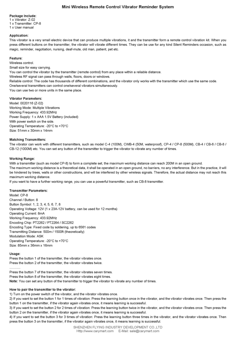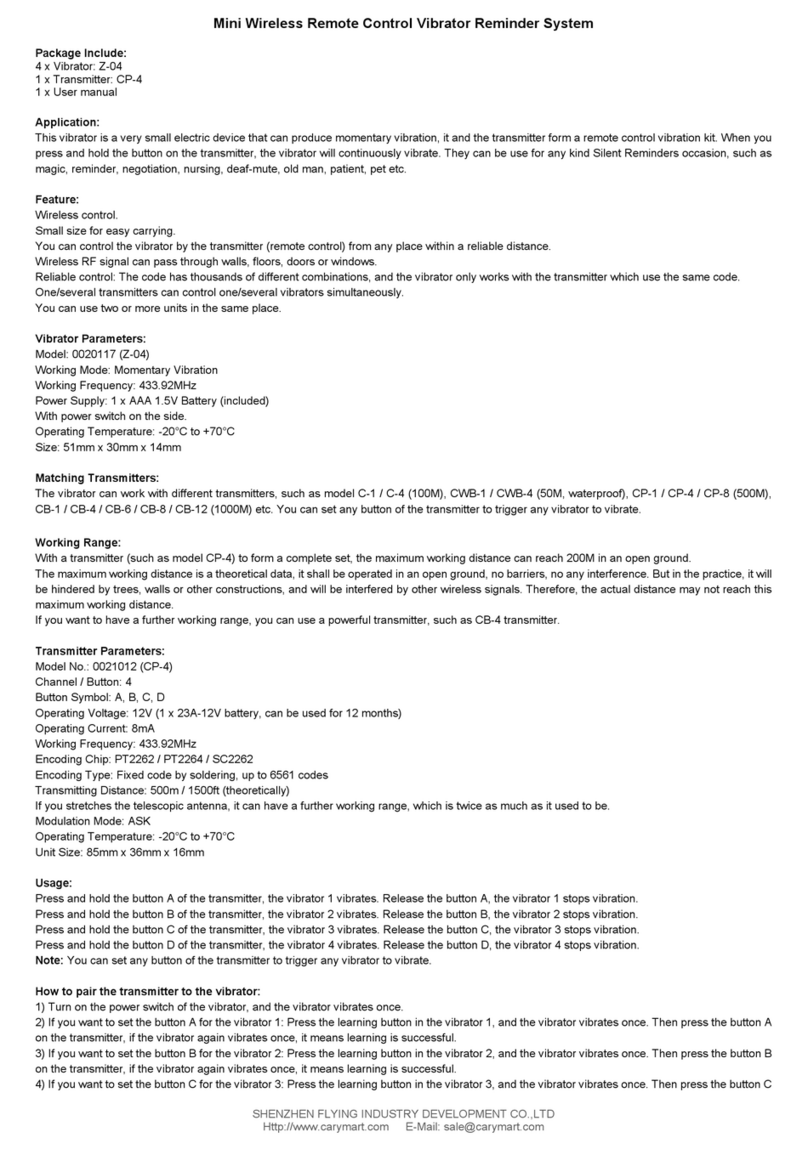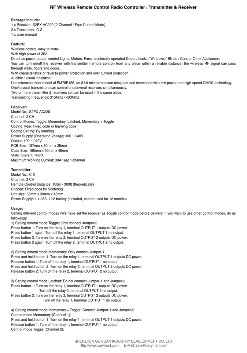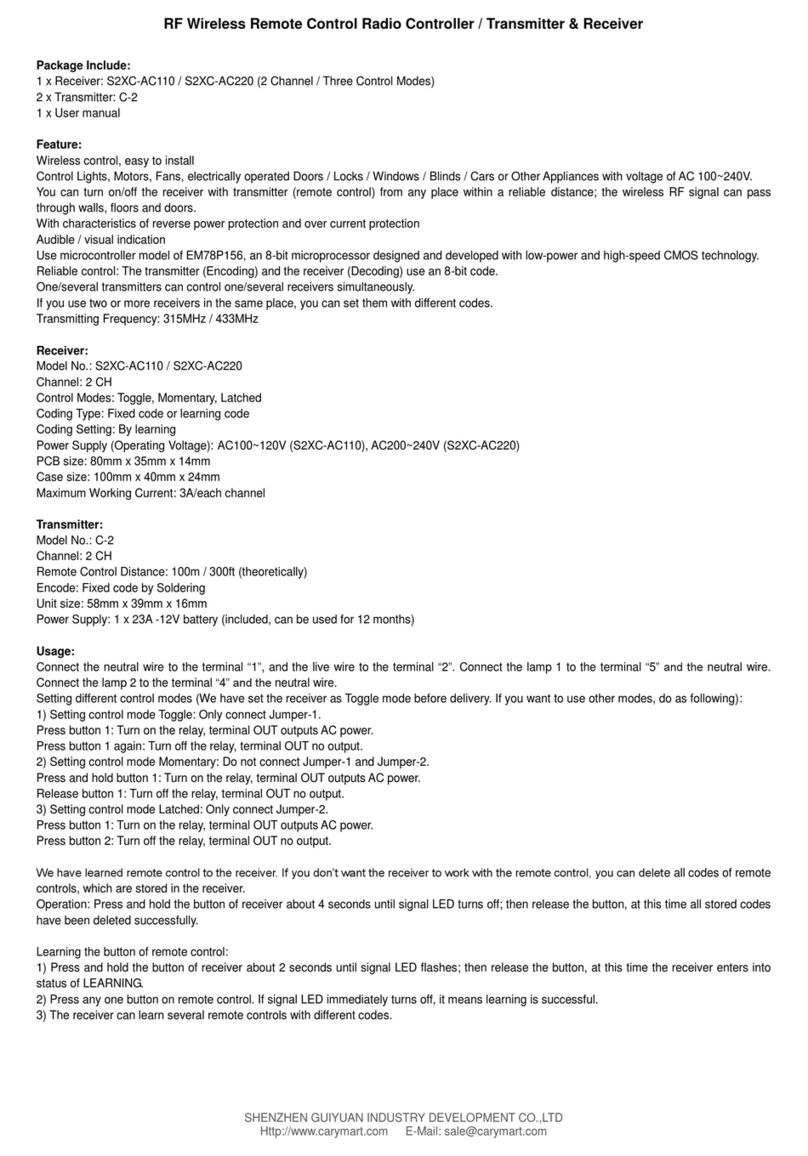
SHENZHENGUIYUANINDUSTRY DEVELOPMENT CO.,LTD
Http://www.carymart.com E-Mail: sale@carymart.com
anotherACor DCdevice through a devicethat has a normally open contact output.
Working process:
1. Connect a deviceA whichwith normally open output to the twoinput lines of the transmitter; connect the other device B to the receiver.
2. When the transmitter's two input lines are connected, it automatically emits an "ON" wireless signal, which is equivalent to the function of the
button "ON" on the transmitter. When thereceiver receives thewireless signal, itwill activate its relay to turn on theconnected device B.
3. When the transmitter's two input lines are disconnected, it automatically emits an "OFF" wireless signal,which is equivalent to thefunction of the
button "OFF" on the transmitter. When the receiver receives thewireless signal, itwill deactivate its relay to turnoff theconnected device B.
Matching Transmitters:
The receiver canworkwith different transmitters,such as model C-2 (100M), CWB-2 (50M,waterproof), CP-2 (500M), or CB-2 (1000M) etc.
Working Range:
Super long range,with a transmitter (such asCB-2N) to forma complete set, the maximumworking distancecanreach2000Min an open ground.
The maximumworking distance is a theoretical data, itshall be operated in an open ground, no barriers,no any interference. But in the practice,itwill
be hindered by trees,walls or otherconstructions, andwill be interfered by other wireless signals. Therefore, the actual distance may not reach this
maximumworking distance.
Usage (with the transmitter like CB-2N):
The receiver can be used to control both DC0~28V andAC 110~240V equipments.
Notice: The receiver is relay output, not DC/ACpow er output. Initial state of relay output terminals: Terminals B and Care Normally Open; Terminals
A and Care Normally Closed.
Wiring:
If youwant to control a DC 12V lamp, do as following:
1) Connect the positive pole of DC pow er supply to terminal “L / +”, andconnect the negative pole of DC pow er supply to terminal “N / -”.
2) Connect terminal B to the positive pole of DC power supply, connect terminal Cto the positive pole of DC lamp, and connect the negative pole of
DC lamp to the negative pole of DCpower supply.
If youwant to control anAC 220V lamp, do as following:
1) Connect the positive pole of DC pow er supply to terminal “L / +”, andconnect the negative pole of DCpow er supply to terminal “N / -”.
2) Connect terminal B to the livewire of ACpower supply,connect terminal C to one side of AClamp, and connect anotherside of AClamp to the
neutralwire of ACpower supply.
Operation:
The receiver paired to this transmitter can be turned on / off by pressing buttons on the transmitter, connecting the red wire and black wire of the
transmitter or connecting the redwire and blackwire to aswitch/sensor.
Controlling the receiver by pressing buttons on the transmitter:
Press buttonA on the transmitter -> On, the device controlled by thereceiverstarts towork;
Press button B on the transmitter -> Off, thedevice controlled by thereceiverstops working.
Controlling the receiver by connecting red wire and black wire of the transmitter:
When connecting the redwire and blackwire of this transmitter, the transmitterwill be triggered and then itwill send an RFsignalof "ON" to turn on
the receiver, the devicecontrolled by the receiver will starts towork.
When disconnecting theredwire and blackwire of this transmitter, the transmitterwill be triggered andthen itwill send an RF signalof "OFF" to turn
off the receiver, thedevice controlled by thereceiverwill stopsworking.
The transmitter can also be triggeredby connecting the redwire and black wire to a switch or asensor,but the switch or sensor must be
normally open (NO).
Wired control terminals:
The receiver has w iredcontrol terminals, you canconnect external devices,sensors, limit switches or manual switches to trigger the receiver.
1) By low level signal:
Youcanconnect external devices (with low level outputsignal) to trigger thereceiver.
When the externaldevice outputs low level signalto terminal 1 (Signal -) and terminal 2 (Signal +), the receiver turns on the relay.(Connect B and C,
disconnectA and C), the devicecontrolled by thereceiverwill starts towork.
When the external device stops to output signal, the receiver turns off the relay.(Disconnect B and C, connect A and C) , the device controlled by the
receiver will stops working.
2) By NO/NCcontact:
Youcanconnectmanual switches (with NO/NC contact) to trigger thereceiver.
When connect terminals 1 and 2, the receiver turns on the relay. (Connect B and C, disconnect A and C) , the device controlled by the receiverwill
starts towork.
Andwhen disconnect terminals 1 and 2, the receiver turns off the relay. (DisconnectB and C, connectA and C), the devicecontrolled by the receiver
will stops working.
How to pair the transmitter to the receiver:
