CAS Corporation CAW Series User manual

Safety Precautions
The following notation conventions are used in this manual to indicate Safety Precautions.
Note: Provides additional information needed to properly use the balance.
CAUTION
A CAUTION statement indicates a potentially hazardous situation
that may result
in personnel injury or equipment damage.
CAUTION
To ensure the proper operation of the balance, observe the following precautions.
•Do not use the balance in hazardous areas.
This includes areas where the balance is exposed to dust and flammable
gases or
liquids.
ŸUse the AC adapter supplied by CAS.
To prevent the risk of electric shock, never disassemble the AC adapter.
The AC adapter is designed for indoor use. Do not use
the adapter in exterior
environments or where it may be splashed by water.
Ensure that the power supply voltage meets the indicated range of the AC adapter.
ŸHandle the balance carefully.
The balance is a precision instrument
. The door to the weighing chamber is glass,
open and close it carefully.
ŸDo not connect the peripheral devices other than those recommended by CAS
to the
balance.
The balance may not operate properly if peripheral devices other than those
specified
in this manual are used. When using the RS-
232C interface, follow the instructions
in Section 34. “Windows
DIRECT FUNCTION” and Section
37. “Configuration
Diagram of Peripheral Units.”
ŸDO NOT disassemble the balance, accessories, or peripheral unit.

INTRODUCTION
The CAS corporation CAW, CAX, and CAY series electronic balances are high
performance, multiple function balances.
The CAW/CAX/CAY series of balances are equipped with various application
weighing functions, and unit conversion functions. These functions allow for a great
variety of applications when used in conjunction with the peripheral units described in
this manual.
The CAW/CAX series of balancesincorporates clock functions, a built-in motor-driven
calibration weight that can automatically calibrate sensitivity without the use of
external weights and also has ISO and GLP corresponding outputs included in the
standard specifications.
Read this manual carefully and keep it with the balance for future reference.

CONTENTS
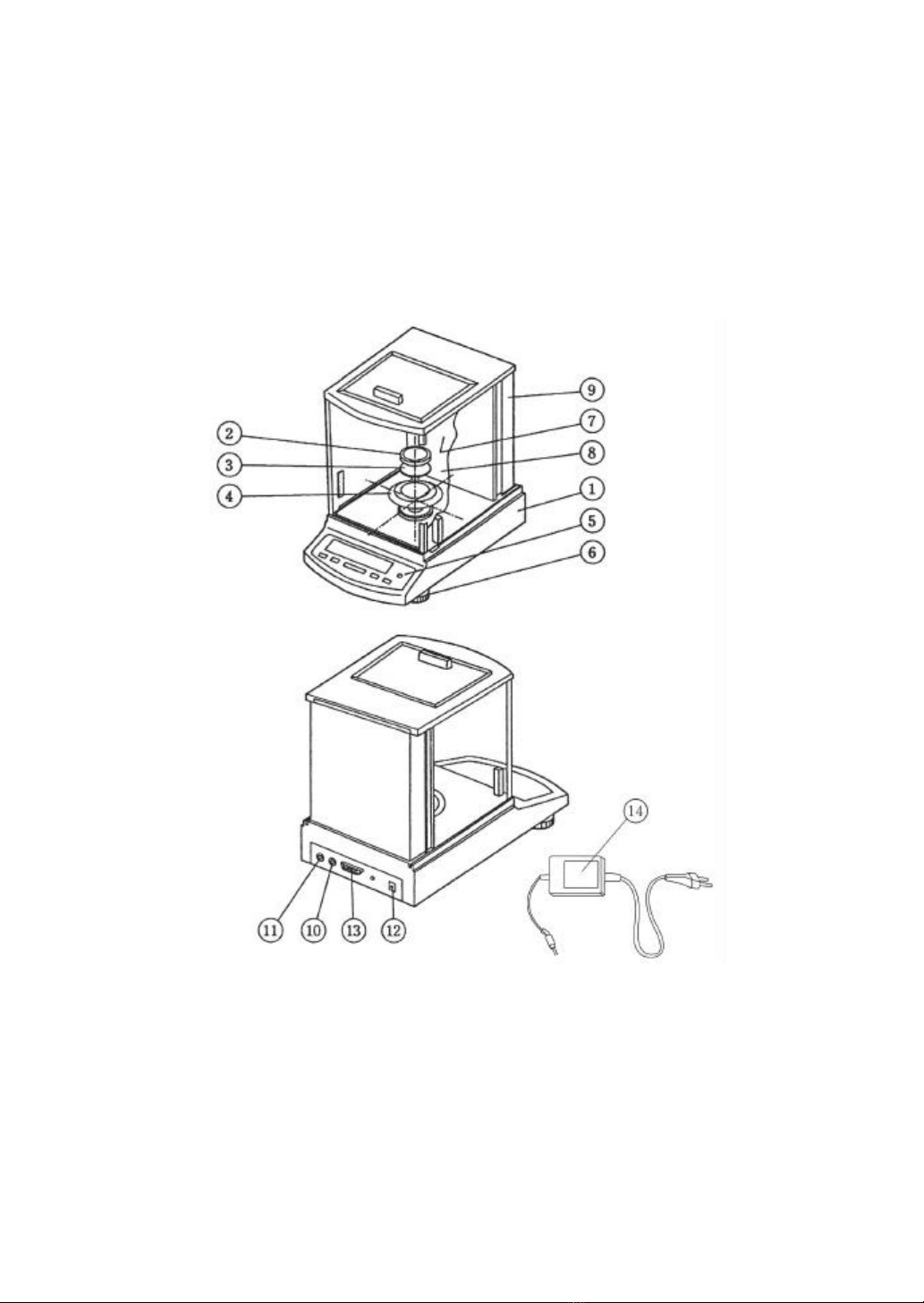
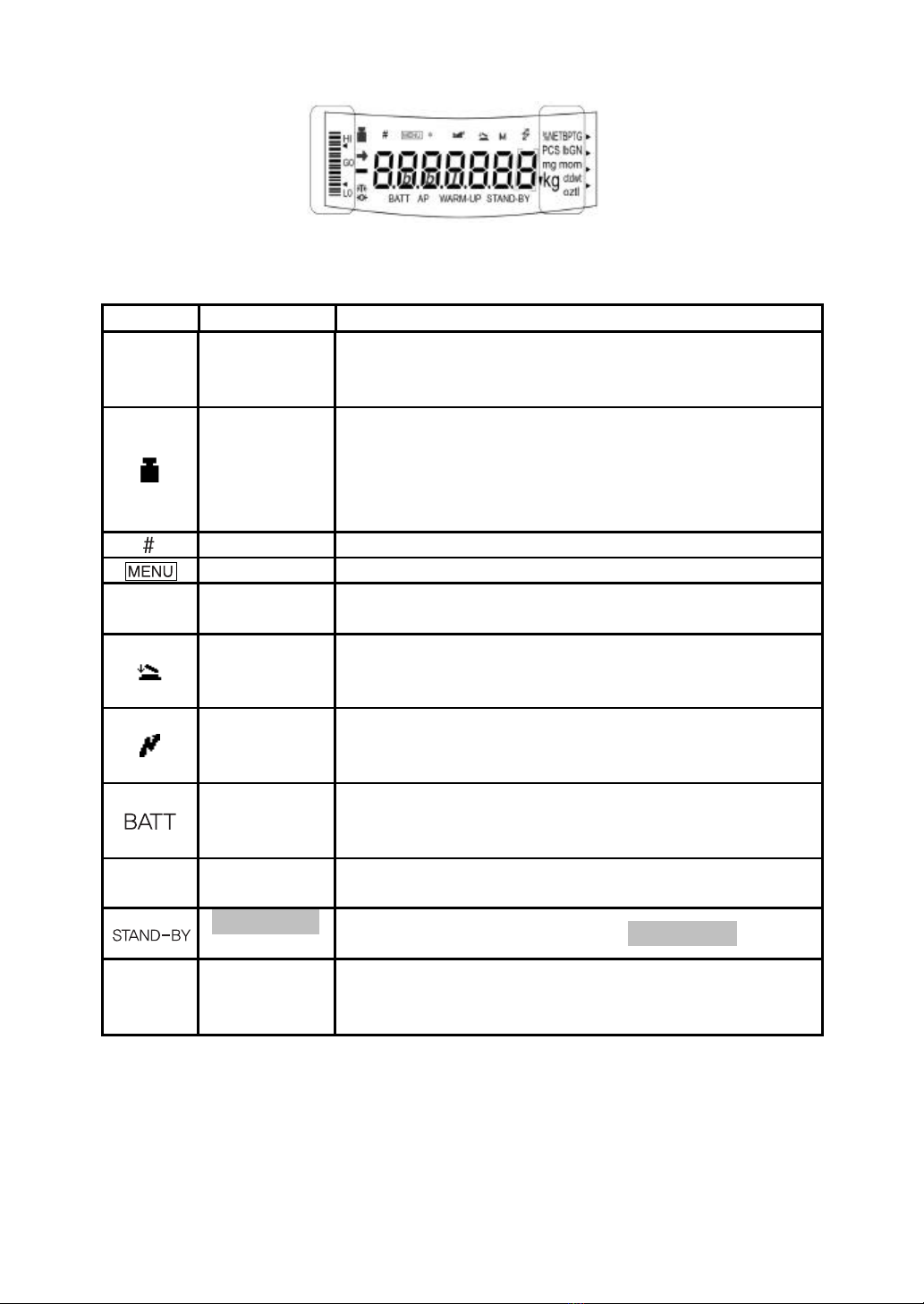
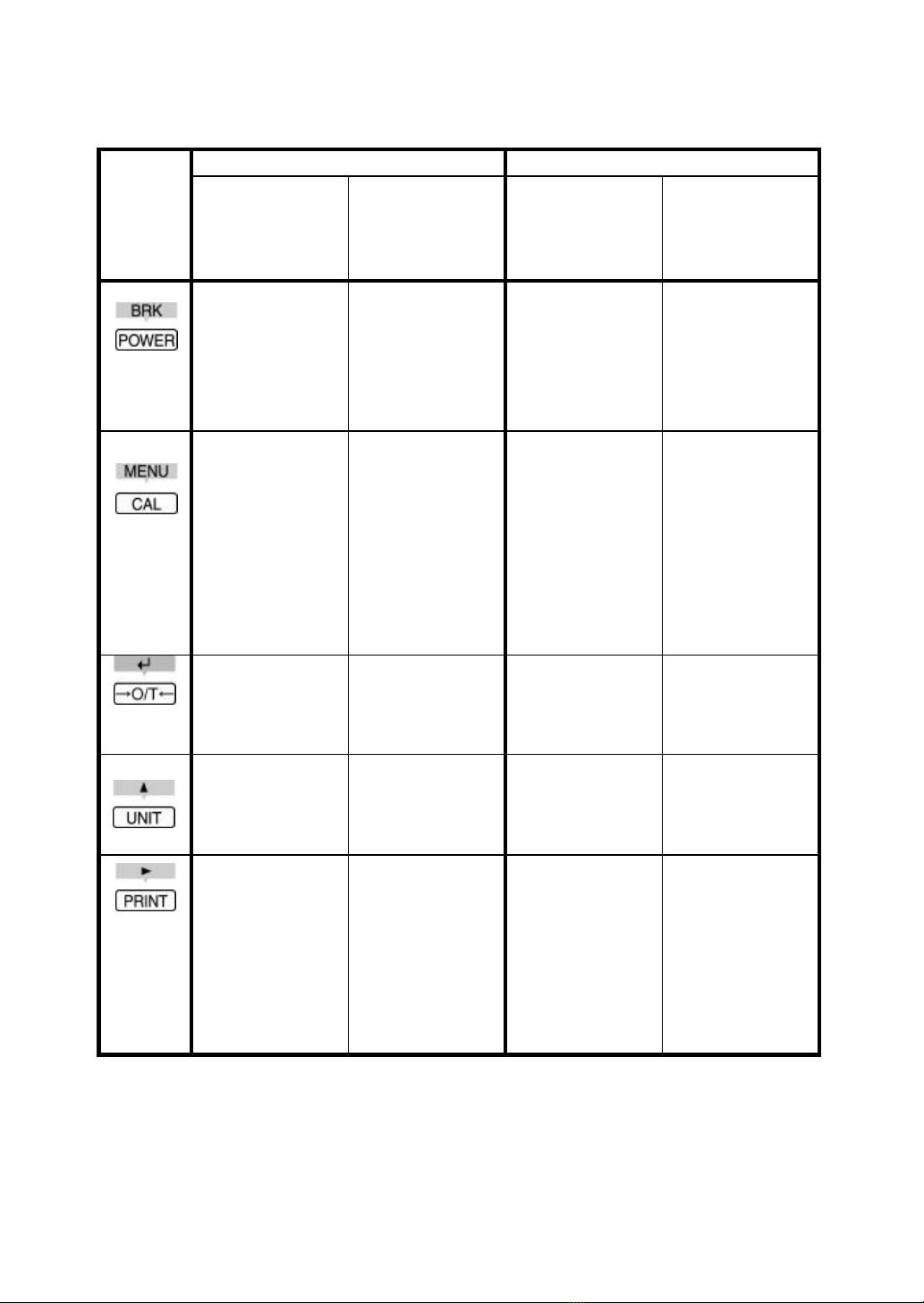
1. BALANCE COMPONENTS.................................................................................1
2. INSTALLATION..................................................................................................5
3. WARM-UP..........................................................................................................6
4. PRECAUTIONS..................................................................................................6
5. MEASUREMENT PROCEDURE.........................................................................7
6. MENU SELECTION............................................................................................7
6.1 OPERATION MENU...........................................................................................8
6.2 FUNC.SEL MENU.........................................................................................10
6.3 SETTING MENU ............................................................................................12
6.4 INTFACE MENU............................................................................................16
6.5 UNIT.SEL MENU ...........................................................................................18
6.6 IF:USER MENU.............................................................................................20
7. SPAN CALIBRATION (SENSITIVITY ADJUSTMENT).......................................22
7.1 SPAN CALIBRATION USING THE BUILT-IN WEIGHT.............................................22
7.2 SPAN CALIBRATION USING AN EXTERNAL WEIGHT ...........................................23
7.3 SPAN CHECK USING THE BUILT-IN WEIGHT......................................................24
7.4 SPAN CHECK USING AN EXTERNAL WEIGHT ....................................................25
8. ZERO TRACKING ............................................................................................26
9. STABILITY DETECTION BAND ........................................................................26
10. REGISTRATION, RELEASE, AND SELECTION OF MEASURE-MENT UNITS .26
10.1 PERCENTAGE................................................................................................27
10.2 NUMBER OF PIECES.......................................................................................28
10.3 SOLID SPECIFIC GRAVITY...............................................................................29
10.4 LIQUID SPECIFIC GRAVITY..............................................................................30
11. AUTO PRINT ....................................................................................................31
12. ANALOG DISPLAY...........................................................................................31
13. ADD LOAD WEIGHING ....................................................................................32
14. STANDARD SPAN CALIBRATION (SENSITIVITY ADJUSTMENT)...................33
15. EXTERNAL WEIGHT VALUE FOR SPAN CALIBRATION.................................34
16. EXTERNAL WEIGHT VALUE FOR BUILT-IN WEIGHT CALIBRATION
(CAW/CAX SERIES ONLY) ..............................................................................34

17. CALIBRATION OF THE BUILT-IN WEIGHT (CAW/CAX SERIES ONLY)...........35
18. BALANCE ID NUMBER....................................................................................35
19. OUTPUT CORRESPONDING TO GLP/GMP....................................................36
20. AUTOMATIC SPAN CALIBRATION (PSC)(CAW SERIES ONLY) .....................37
21. CLOCK-CAL (CAW SERIES ONLY)..................................................................38
22. CLOCK-CAL STARTING TIME (CAW SERIES ONLY) ......................................38
23. SOLVENT SPECIFIC GRAVITY FOR SOLID SPECIFIC GRAVITY
MEASUREMENT ..............................................................................................39
24. SINKER VOLUME FOR LIQUID SPECIFIC GRAVITY MEASUREMENT ...........40
25. DATE (CAW/CAX SERIES ONLY) ....................................................................40
26. TIME (CAW/CAX SERIES ONLY) .....................................................................41
27. PRINTING THE DATE & TIME (CAW/CAX SERIES ONLY)...............................42
28. PERFORMANCE CHECK.................................................................................42
29. MAINTENANCE................................................................................................44
30. TROUBLESHOOTING ......................................................................................44
30.1 ERROR MESSAGE..........................................................................................46
31. SPECIFICATIONS ............................................................................................47
32. PARTS LIST.....................................................................................................51
33. USING PERIPHERAL UNITS............................................................................51
34. WINDOWS®DIRECT FUNCTION.....................................................................52
35. INPUT AND OUTPUT DATA FORMAT .............................................................55
36. COMMAND CODE ...........................................................................................56
37. CONFIGURATION DIAGRAM OF PERIPHERAL UNITS...................................58

1
1. BALANCE COMPONENTS
Composition:
The Instruction Manual and Inspection Acceptance Certificate & Installation
Tag are included along with the items depicted below. Verify that all of the
items are included in the shipping carton.
Name of Each Part:
1. Main Balance Body 2. Pan 3. Pan Supporter
4. Anti-draft Ring 5. Level 6. Leveling Screw
7. Glass Doors 8. Weighing Chamber 9. Case Side Wall
10. Keyboard
Connector 11. DATA I/O
Connector 12. DCIN Connector
13. RS-232C Connector 14. AC Adapter
Symbol Displays

2
Analog display Unit display
An example of ìwhole lightingî display.
Display How to read Meaning during weighing
Stability
symbol
In mass display this symbol indicates that the balance
is stable. In menu display, this symbol indicates the
current menu setting. (*1)
Weight
symbol
Blinks when sensitivity adjustment is necessary. This
symbol continues to blink until either a manual or
automatic sensitivity adjustment is made. This symbol
also blinks when the pre-set time for the Clock-CAL
function is reached.
Num symbol Indicates numeric value entry.
Menu symbol Illuminates during menu selection.
*Asterisk Indicates that the displayed numeric value is not a
mass value.
Add Load
Weighing
symbol
Indicates that Add Load Weighing is ON for the
application measurement function.
Communicati
on symbol
Illuminates during communication to external
equipment through the RS-232C or DATA I/O
connector.
Battery
symbol
When the balance is operated with the optio nal
external battery pack, this symbol illuminates to
indicate that the battery voltage has dropped.
AP Auto-Print
symbol
Indicates that Auto-Print is ON for the application
measurement function.
STAND-BY
symbol Illuminates when the power is in STAND-BYmode.
Inverse
triangle
symbol
Illuminates when the solid specific gravity unit is
used. This symbol is also used as a substitute for the
decimal point.
*1 Stability symbol
The displayed value may change while the stability symbol remains
illuminated if the load is changing slowly or if the stability detection
band has been set to a large value.
▼

3
Key Functions
During weighing During menu selection (*1)
Key Pressing Once
and Releasing Pressing and
Holding for
About 3
Seconds
Pressing Once
and Releasing Pressing and
Holding for
About 3
Seconds
Switches
between the
operation and
STAND-BY
modes.
Exits the
Application
Measurement
function.
Returns to the
previous menu. Returns to the
mass display.
Enters
sensitivity
calibration or
menu selection.
Sets the sample
weight in the air
for solid specific
gravity
measurement.
Enters the
setting menus
when piece
counting or %
units are
displayed.
Moves to the
next Menu Map
item.
Tares the
balance.
(Displays zero)
(*5)
Selects and sets
the currently
displayed Menu
Map item.
Changes the unit
selection. (*2) Switches
between the 1d
and 10d display.
(*3)
Increases the
numeric value of
the blinking
digit by 1.
Sends the
displayed value
to an attached
peripheral
device.
During
STAND-BY or
mass display,
the current time
is sent to an
attached
peripheral
device. (*4)
Moves the
blinking cursor
to the next digit.
*1 Refer to Section 6. “MENU SELECTION”.
*2 Units other than “g” must be registered and set before they can be used for
measurement. Gramme (or gram) (g) is the only unit that is registered

4
before shipment. To register other units, refer to Section 10.
“REGISTRATION, RELEASE, AND SELECTION OF MEASUREMENT
UNITs”.
*3 When the unit is set to 10d, the resolution of the minimum display is
decreased by one decimal place.
*4 Applicable to CAW/CAX Series balances only.
*5 TARE may be printed on the key instead of →O/T←. However, the
functions of the key are the same.

5
2. INSTALLATION
Power Supply Voltage
• Do not use any AC adapters other than the one provided as a
standard accessory.
• Confirm the power supply voltage.
• Confirm that the voltage of the power supply conforms to the one
indicated on the AC adapter.
Installation Site
The ideal operating environment for the balance is in a location where
the temperature is 20°C ± 2°C with a relative humidity of 45 -60%
RH and the conditions are stable.
Install the balance on a solid table. Ideally the table should be made of
stone. Choose a site that is dust free and is not exposed to vibrations,
wind, direct sunlight or electromagnetic fields.
Do not place the balance in an environment where it will be
exposed to corrosive or flammable gasses.
Installation Procedure
(1) Install the pan supporter then the anti-draft ring and finally the pan
in this order.
(2) Level the balance by turning the leveling screws to bring the bubble
of the level indicator into the red circle.
(3) Verify that the pan is empty and connect the AC adaptor to the
outlet.
(4) After self-check, the balance automatically performs span
calibration and OFF is displayed. It is not possible to interrupt the
span calibration that occurs right after the power is turned ON. Span
calibration is not performed with the CAY series balances.
(5) Press the POWER/BRK key. “Whole lighting” is displayed for
about 1 second then the balance automatically goes to a zero mass
display and the balance is ready for weighing.
(6) Press the POWER/BRK key in the mass display to put the balance
in the STAND-BY mode. The STAND-BY symbol illuminates
indicating that the balance is in the STAND-BY mode.
(7) Allow the balance to warm up for 4 hours in the STAND-BY mode.
(8) Conduct the Performance Check. FSee Section 28. “Performance
Check.”
(9) Set the date and time on the balance.
FSee Section 25 “DATE” and Section26 “TIME.”

6
Moving the Balance
• Before moving the balance, confirm that it is not in the process of
span calibration. Unplug the AC adapter from the power outlet
and transfer the balance.
Disconnecting the power supply or moving the balance during span
calibration or check may cause balance failure.
3. WARM-UP
• Warming-up the balance for at least four (4) hours allows for
accurate measurement.
• Do not disconnect the AC adapter even when the balance is not in
use.
Instead, press the POWER/BRK key to put the balance in the
STAND-BY (warm-up) mode.
• Disconnect the AC adapter from the outlet if the balance will not
be used for a period of one month or longer.
4. PRECAUTIONS
Observe the following precautions.
Note:
• Do not insert metal tools inside the balance housing.
• Do not open the balance housing.
• Do not allow water or other liquids to enter the balance housing.
• Do not place a load on the pan that exceeds the mass range of the
balance.
• Do not allow magnetized articles near the balance.
• Do not connect any instruments to the balance connectors other
than those designated in this manual.
• Do not drop anything on the pan.
• The doors to the weighing chamber are glass. Open and close
them carefully.
• Before transporting the balance, pack the balance into the original
shipping carton to prevent damage.

7
5. MEASUREMENT PROCEDURE
Preparations Before Measurement
Warm-up the balance before starting measurement.
Setting the Measuring Mode
(1) Press the POWER/BRK key.
(2) The STAND-BY indicator goes out and whole lighting is displayed.
Verify that all segments of the display illuminate.
If the balance is set to automatically perform span calibration it is
executed before zero is displayed.
(3) Zero is displayed and the balance is in the measuring mode.
Measurement
(1) If a weighing vessel (tare) is used, place it on the pan and wait for
the stability symbol ( ) to illuminate, then press the →O/T←key.
(2) Verify that 0 is displayed.
(3) Add the sample and read the display after the stability symbol
appears.
6. MENU SELECTION
This balance is designed to ensure efficient measurement by selecting
measuring parameters to properly fit the environment and purpose of the
weighing. Use Menu Selection to edit the measurement parameters.
The menu of an CAW, CAX, and CAY series balance consists of four levels.
Press the CAL/MENU key to cycle through the items within a menu level.
Press the →O/T←key to choose the current item or move to the next menu
level. Press the POWER/BRK key to move back one level. Press and hold
the POWER/BRK key for more than three seconds to return to the mass
display.

8
6.1 Operation Menu
Frequently used menus are contained in the first menu level
(1) Press the CAL/MENU key during mass display.
(2) "i CAL" (or standard span calibration) is displayed. (CAW/CAX
series only)
(3) The display changes each time the CAL/MENU key is pressed.
When the desired item is displayed, press the →O/T←key to select
it.
(→): Press the →O/T←key (←): Press the POWER/BRK key
(↓): Press the CAL/MENU key
0.0000 →Mass display
iCAL →Performs selected standard span calibration. (CAW/CAX
series only)
St.b1t →A display of the currently set conditions FSee the example of
the default conditions at the bottom of this page.
Stnd →Sets the Standard Measurement mode
SAmPLE →Sets the Sample Pouring mode
Hi-Stb →Sets the High Stability mode
FUnC.SEL ↔Enters the next menu level (application measurement
and individual setting modes).
FSee Section 6.1 “FunC.SEL Menu.”
SettinG ↔Enters the next menu level (system setting mode).
FSee Section 6.2 “SEttinG Menu.”
IntFACE ↔Enter the next menu level (input/output format setting
mode).
FSee Section 6.3 “intFACE Menu.”
• Normal measurement is performed with the CAW, CAX, and CAY
series balances by setting the balance to "Stnd" (Standard
Measurement mode). No other settings are required.
• If the balance environment is poor and the display does not stabilize
easily, select "Hi-Stb" (High Stability mode).
• To perform high speed sampling or sample minute amounts, select
"SAmPLE" (Sample Pouring mode).
(→): Press the →O/T←key (←): Press the POWER/BRK key
(↓): Press the CAL/MENU key

9
Display of the Currently Set Conditions (Example)
The current balance conditions are displayed in abbreviation.
Indicates that automatic span Indicates that the GLP
calibration is ON. corresponding output is
ON.
St.b1 t
Measuring mode Stability detection band Zero tracking
Standard: St 0.1mg: b1 ON: tis displayed.
Sample Pouring: SA 0.5mg: b5 OFF:tis not
displayed.
High Stability: Hi 1.0mg: b10

10
6.2 FUnC.SEL Menu
From the mass display, press the CAL/MENU key repeatedly until
"FUnC.SEL" is displayed. Press the →O/T←key to enter the next menu
level. Items in this menu level include span calibration, zero tracking,
stability detection band, selection or release of units, automatic PRINT,
analog display and Add Load Weighing.
FUnC.SEL CAL E CAL →Starts span
calibration using the external
weight.
E tESt→Starts span check using the
external weight.
i CAL →Starts span calibration using the
built-in weight. (CAW/CAX
series only)
i tESt →Starts span check using the
built-in weight. (CAW/CAX
series only)
trC:on trC-on→Sets Zero tracking ON.
trC-oF→Sets Zero tracking OFF.
bAnd:1 b-1→Sets the stability detection band
to 1 count.
b-5→Sets the stability detection band
to 5 counts.
b-10 →Sets the stability detection band
to 10 counts.
Unit.SEL↔Enters into the next menu level (unit
selection mode)
FSee Section 6.4 “Unit.SEL Menu"
AtPrt:on AP-on→Sets Automatic PRINT ON.
AP-oF→Sets Automatic PRINT OFF.
AdiSP:on Ad-on→Sets Analog display ON.
Ad-oF→Sets Analog display OFF.

11
Addon:on Adon-on →Sets Add Load
Weighing mode ON.
Adon-oF →Sets Add Load
Weighing mode OFF.
(→): Press the →O/T←key (←): Press the POWER/BRK key.
(↓): Press the CAL/MENU key.
• For better stability at zero point, set the zero tracking ("trC-on" and
"trC-oF") to "trC-on." To observe the variation of the mass amount when
a liquid or powder is slowly injected, set zero tracking to "trC-oF."
• The stability detection band is normally set to "b-1."
• When the stability detection band is set larger, a less stable mass display
is required to light the stability mark.

12
6.3. SEttinG Menu
From the mass display, press the CAL/MENUkey repeatedly until
"SEttinG" is displayed. Press the →O/T←key to enter into the next menu
level. Items that are set in this menu level include calibration of the built-in
weight, standard span calibration, external weight value for span calibration,
external weight value for calibration of the built-in weight, balance ID,
solvent and sinker specific gravity, execution time for Clock-CAL, date,
time, printing corresponding to GLP/GMP, automatic span calibration,
Clock-CAL and date/time print.
Operate the keys according to the following descriptions to set each item.
Select standard span calibration method:
SEttinG CAL dEF E CAL →Sets the span calibration
with the external weight.
E tEST →Sets the span check
with the external weight.
i CAL →Sets the span calibration with
the built-in weight. (CAW/CAX
series only)
i tESt →Sets the span check with the built-
in weight. (CAW/CAX series
only)
CAL SEt↔Enters the next menu level (external weight
value setting mode).
FSee Section 15. “EXTERNAL WEIGHT
VALUE FOR SPAN CALIBRATION.”
PCAL.SEt ↔Enters the next menu level
(setting mode of an external weight value
for the built-in weight calibration). *1
FSee Section16. “EXTERNAL WEIGHT
VALUE FOR BUILT-IN WEIGHT
CALIBRATION.”
PcAL ↔Enters the next menu level (calibration
mode of the built-in weight). *1
FSee Section 17. “CALIBRATION OF
THE BUILT-IN WEIGHT.”
id:1234 ↔Enters the next menu level (Balance ID
setting mode).
FSee Section 18. “BALANCE ID
NUMBER.”
GLP:on GLP-on →Sets the GLP/GMP
corresponding output to ON.
GLP-oF →Sets the GLP/GMP
corresponding output to OFF.

13
ACAL:on ACAL-on→Sets automatic span
calibration to ON. (CAW series
only)
ACAL-oF→Sets automatic span
calibration to OFF. (CAW series
only)
AB
(→): Press the →O/T←key (←): Press the POWER/BRK key.
(↓): Press the CAL/MENU key.

14
AB
tCAL:on tCAL-on →Set Clock-CAL to
ON. (CAW series only)
tCAL oF →Set Clock-CAL to
OFF. (CAW series only)
tCAL t1 ↔Enters the next menu level (Clock-CAL
automatic span calibration time setting
mode). (CAW series only)
FSee Section 22.“Clock-CALSTARTING
TIME.”
tCAL t2 ↔Enters the next menu level (Clock-CAL
automatic span calibration time setting
mode). (CAW series only)
FSee Section 22. “Clock-CAL
STARTING TIME.”
tCAL t3 ↔Enters the next menu level (Clock-CAL
automatic span calibration time setting
mode). (CAW series only)
FSee Section 22. “Clock-CAL
STARTING TIME.”
LSG SEt↔Enters the next menu level (setting of the
solvent specific gravity for solid specific
gravity measurement)
FSee Section 23. “SOLVENT SPECIFIC
GRAVITY FOR SOLID SPECIFIC
GRAVITY MEASUREMENT.”
Sv SEt ↔Enters the next menu level (setting of the
sinker volume for liquid specific gravity
measurement)
FSee Section 24. “SINKER VOLUME
FOR LIQUID SPECIFIC GRAVITY
MEASUREMENT.”
d-01.21 ↔Enters the next menu level (date setting
mode). (CAW/CAX series only)
FSee Section 25. “DATE.”

15
t-16:50 SEC AdJ ↔Enters the next menu level
(±30 sec adjustment mode).
(CAW/CAX series only)
FSee Section 26. “TIME.”
tm.AdJ ↔Enters the next menu level
(time setting mode).
(CAW/CAX series only)
FSee Section 26. “TIME.”
Prtdt:on Prdt-on →Sets Date and time PRINT ON.
(CAW/CAX series only)
Prdt-oF →Sets Date and time PRINT OFF.
(CAW/CAX series only)
(→): Press the →O/T←key (←): Press the POWER/BRK
key. (↓): Press the CAL/MENU key.

16
6.4 intFACE Menu
From the mass display, press the CAL/MENU key repeatedly until
"intFACE" is displayed. Press the →O/T←key to enter the next menu level.
Select the input and output format in this menu. Five preset configurations
are available.
Select a standard format to set the registered baud rate, parity (and bit
length), stop bit, delimiter, and data format all at the same time.
A user format is provided in addition to the preset formats. The user can edit
the communication parameters individually in the user format.
IntFACE iF :F1 →Sets format 1.
iF :F2 →Sets format 2.
iF :F3 →Sets format 3.
iF :F4 →Sets format 4.
iF :win →Windows®Direct format.
FSee Section 34. “Windows®Direct
Function.”
iF :USEr ↔Enters the third hierarchical menu (user
format setting). FSee Section 6.5 “iF:USEr Menu.”
(→): Press the →O/T←key (←): Press the POWER/BRK key.
(↓): Press the CAL/MENU key.
This manual suits for next models
9
Table of contents
Other CAS Corporation Scale manuals

CAS Corporation
CAS Corporation nBody-EP User manual

CAS Corporation
CAS Corporation PD-II Series User manual

CAS Corporation
CAS Corporation SW-1S User manual

CAS Corporation
CAS Corporation ER PLUS Series User manual

CAS Corporation
CAS Corporation SW-1S User manual

CAS Corporation
CAS Corporation SW-2 User manual

CAS Corporation
CAS Corporation EB User manual

CAS Corporation
CAS Corporation DB-II User manual