CAS Corporation ER PLUS Series User manual

ERPLUS Service Manual
1 9/27/2010
ERPLUS SERVICE MANUAL

ERPLUS Service Manual
2 9/27/2010
< Table of Contents >
1. Introduction ............................................................................................................................... 4
1.1. Preface .................................................................................................................................... 4
1.2. Precaution............................................................................................................................. 4
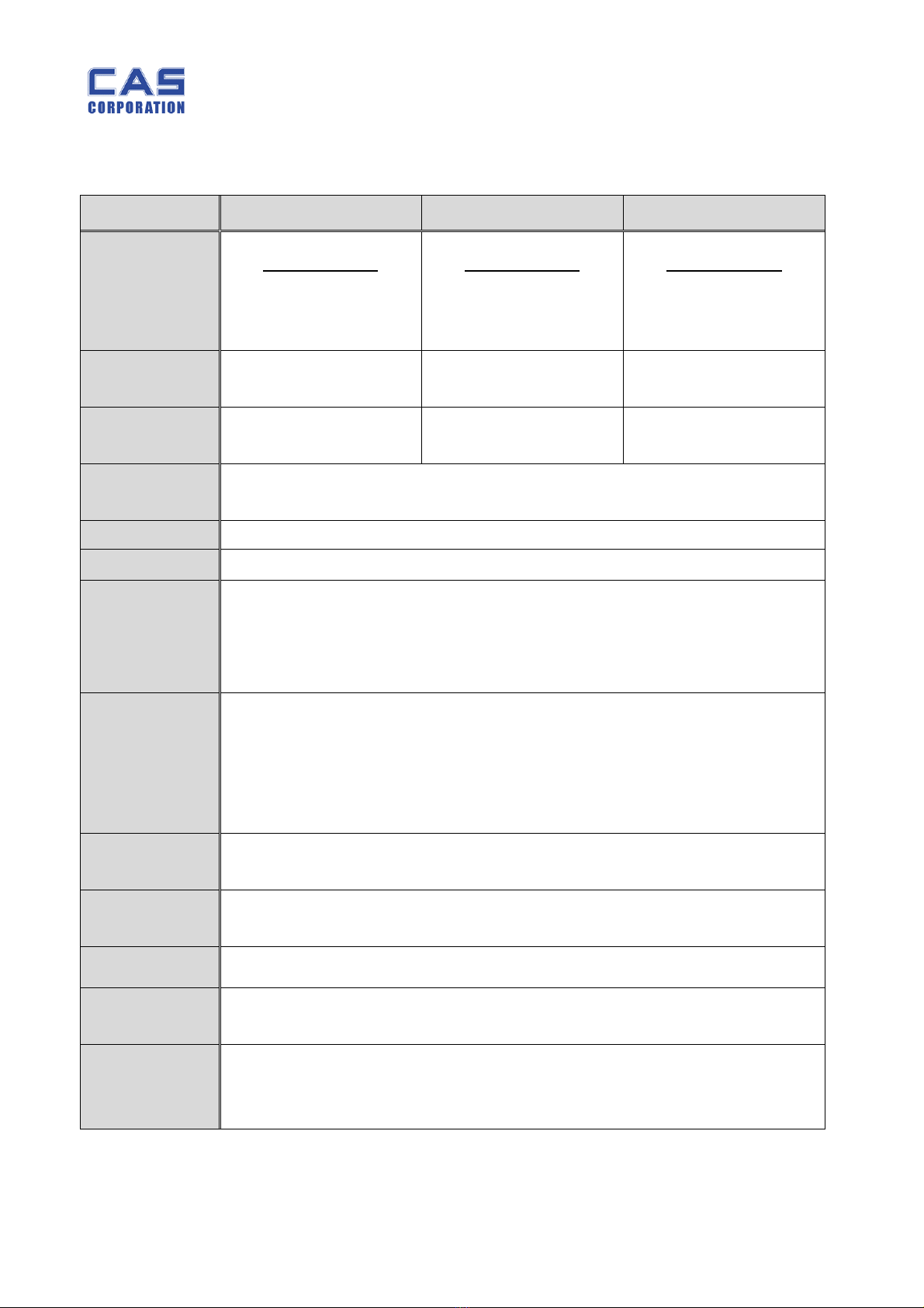
1.3. Specification ........................................................................................................................ 5
1.3.1. Kilogram (kg) Version.............................................................5
1.3.2. Pound (lb) Version .................................................................6
1.4. ERPLUS LCD Version............................................................................................................ 7
1.5. ERPLUS VFD Version ........................................................................................................... 7
1.6. ERPLUS LED Version............................................................................................................ 7
1.7. ERPLUS-M LCD Version........................................................................................................ 7
1.8. ERPLUS-M LED Version........................................................................................................ 7
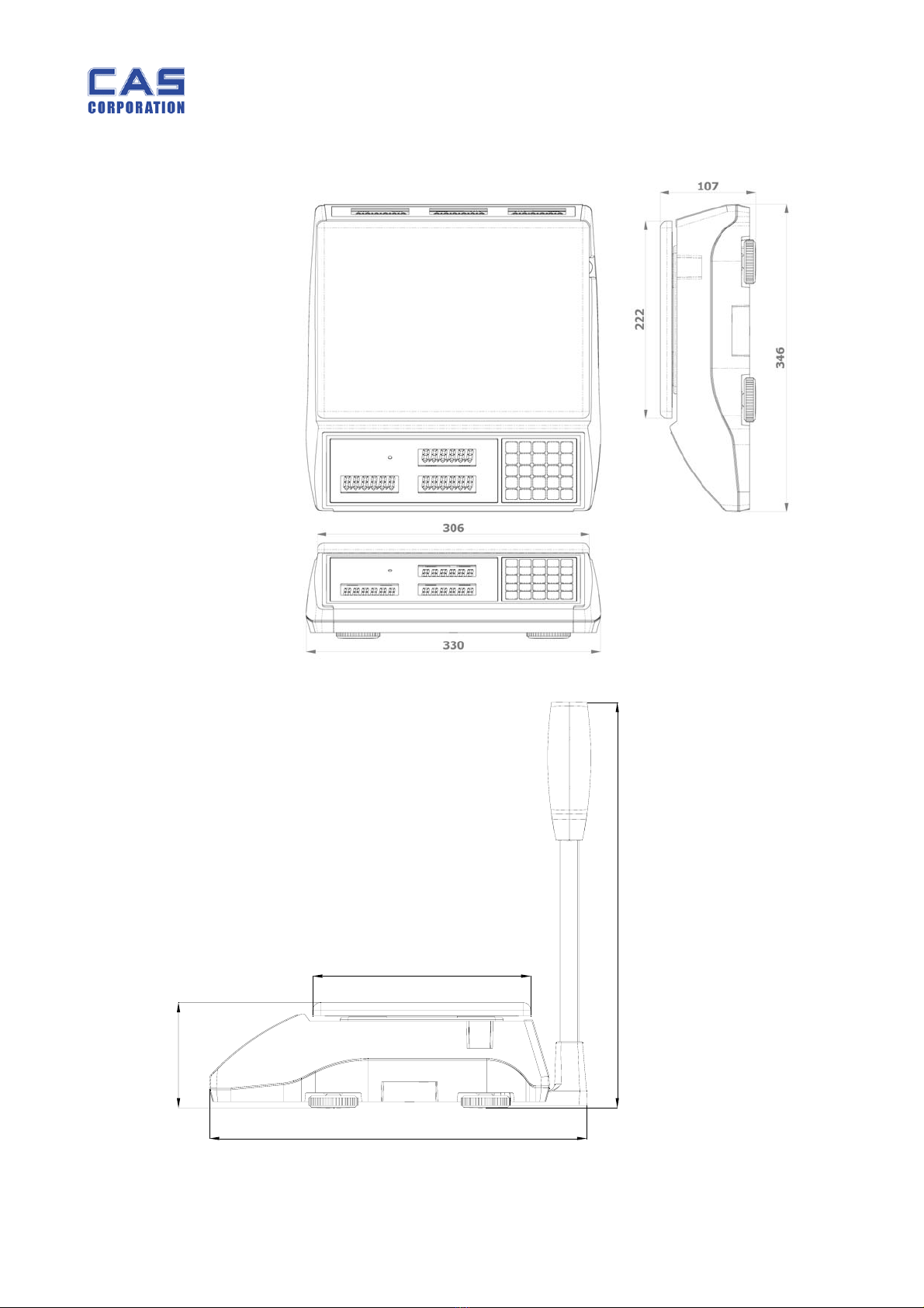
1.9. Dimension.............................................................................................................................. 8
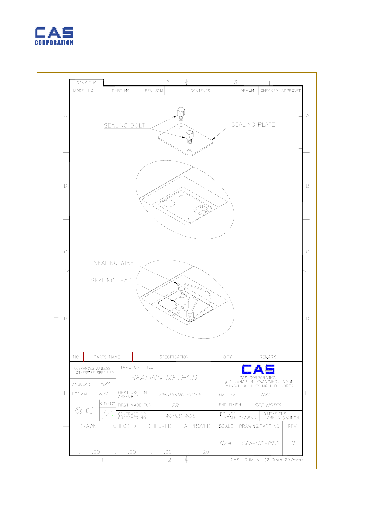
1.10. Sealing Method.......................................................................................................... 9
2. Calibration................................................................................................................................. 11
2.1. General Calibration........................................................................................................ 11
2.1.1. C4 Setting........................................................................... 12
2.1.1.1. C4-1 Setting (AD) ........................................................ 12
2.1.1.2. C4-2 Setting (Sale functions) ...................................... 12
2.1.1.3. C4-3 Setting (Sale functions) ...................................... 13
2.1.1.4. C4-4 Setting (Sale functions) ...................................... 13
2.1.1.5. C4-5 Setting (Sale functions) ...................................... 13
2.1.2. SPAN Calibration Setting (C-3)............................................... 14
2.1.3. Gravity Constant Value Setting (C-9) ...................................... 14
2.1.4. Calibration factor Setting (C-10). ........................................... 14
2.1.5. Displaying Raw A/D Value (C-5) ............................................. 16
2.1.6. Allocate Function Key Codes to Changeable keys (C-6).............. 17
2.1.7. Percent Calibration (C-7)....................................................... 19
2.1.8. Battery Calibration (C-8)....................................................... 19
3. The Schematics and Diagram......................................................................................... 20
3.1. System Block Diagram................................................................................................. 20
4. Exploded View......................................................................................................................... 21
5. Load Cell drawing.................................................................................................................. 23
6. Part Location............................................................................................................................ 24
6.1. ERPLUS LCD Version.......................................................................................................... 24
6.1.1.1. Main PCB Part Location................................................ 24

ERPLUS Service Manual
3 9/27/2010
ERPLUS LCD MAIN .................................................................................. 24
6.1.1.2. FRONT DISPLAY PCB Part Location.............................. 25
ERPLUS LCD FRONT DISPLAY.................................................................... 25
6.1.1.3. REAR DISPLAY PCB Part Location ................................ 26
ERPLUS LCD REAR DISPLAY...................................................................... 26
6.1.1.4. POLE DISPLAY PCB Part Location ................................ 27
ERPLUS LCD FRONT DISPLAY.................................................................... 27
ERPLUS LCD REAR DISPLAY...................................................................... 28
6.1.2. ERPLUS VFD Version ............................................................... 29
6.1.2.1. Main PCB Part Location................................................ 29
ERPLUS VFD MAIN .................................................................................. 29
6.1.2.2. VFD FRONT DISPLAY PCB Part Location..................... 30
ERPLUS VFD FRONT DISPLAY.................................................................... 30
6.1.2.3. VFD REAR DISPLAY PCB Part Location......................... 31
ERPLUS VFD REAR DISPLAY...................................................................... 31
6.1.2.4. POLE DISPLAY PCB Part Location ................................ 32
ERPLUS VFD POLE DISPLAY TYPE #1 ......................................................... 32
ERPLUS VFD POLE DISPLAY TYPE #2 ......................................................... 33
6.1.3. ERPLUS LED Version ............................................................... 34
6.1.3.1. Main PCB Part Location................................................ 34
6.1.3.2. FRONT DISPLAY PCB Part Location.............................. 35
6.1.3.3. REAR DISPLAY PCB Part Location ................................ 36
6.1.4. ERPLUS-M LCD Version ............................................................. 37
6.1.4.1. Main PCB Part Location................................................ 37
6.1.4.2. Front Display PCB Part Location .................................. 38
6.1.4.3. Rear Display PCB Part Location.................................... 39
6.1.5. ERPLUS-M LED Version ............................................................. 40
6.1.5.1. Main PCB Part Location................................................ 40
6.1.5.2. Front Display PCB Part Location .................................. 41
6.1.5.3. Rear Display PCB Part Location.................................... 42
6.1.6. COMMON PCB...................................................................... 43
6.1.6.1. RS-232 MODULE PCB Part Location.............................. 43
RS-232 PCB (TOP) ................................................................................ 43
RS-232 PCB (BOTTOM) ......................................................................... 43
6.1.6.2. KEY PCB Part Location (Pb) ......................................... 44
7. Error Messages & Solution............................................................................................... 45
8. Part List....................................................................................................................................... 46

ERPLUS Service Manual
4 9/27/2010
Introduction
1.1. Preface
Thank you for purchasing of our CAS scale.
This scale has been designed with CAS reliability, under rigid quality control
and with outstanding performance.
We hope that your departments enjoy with high quality of CAS product.
This manual will help you with proper operations and care of the ER series.
Please keep it handy for the future references.
1.2. Precaution
•Make sure that you plug your scale into the proper power outlet.
•Place the scale on a flat and stable surface.
•Plug into a power outlet 30 minutes before operations.
•Keep the scale away from strong EMI noises may cause incorrect weight readings.
•This scale must be installed in a dry and liquid free environment.
•Do not subject the scale to sudden temperature changes.
•Do not subject the platter to sudden shocks.
•If the scale is not properly level, please adjust the 4 legs at the bottom of the
scale (turn legs clockwise or counterclockwise) so as to center the bubble of the
leveling gauge inside the indicated circle.

ERPLUS Service Manual
5 9/27/2010
1.3. Specification
1.3.1.Kilogram (kg) Version
ERPLUS – 6 ERPLUS – 15 ERPLUS – 30
Capacity
Dual Interval
3 kg / 0.001 kg
6 kg / 0.002 kg
Dual Interval
6 kg / 0.002 kg
15 kg / 0.005 kg
Dual Interval
15 kg / 0.005 kg
30 kg / 0.01 kg
Internal
Resolution 1 / 60,000 1 / 60,000 1 / 60,000
External
Resolution 1 / 3,000 1 / 3,000 1 / 3,000
Display ER PLUS : 5 / 6 / 6 (Weight/Unit Price/Total Price)
ER PLUS-M : 6 / 6 / 8 (Weight/Unit Price/Total Price)
Symbols Power, Zero, Tare, Low battery, Backlight (Option for LCD version)
Interface RS – 232C (Printer Option)
Keys
ZERO(ESC), TARE, MODE, SET(ENTER),
NUMERICAL KEY(0~9),C, POWER ON/OFF, ‘+’,’-‘,’x’,’Σ’,
DIRECT PLU KEY(M1~M5), PLU SAVE, CALL-UP KEY
€ (Euro currency convertible keys)
Function
Weighting
AUTO POWER OFF
BACK LIGHT AUTO ON/OFF
PLU
PRINTER INTERFACE (RS-232)
Product Size Pole Type : 360 (W) x 350 (D) x 410 (H)
Standard Type : 360 (W) x 350 (D) x 106 (H)
Product
Weight
Pole Type : 5.5kg
Standard Type : 4.7kg
Platter Size 304 (W) X 220 (D)
Operating
Temperature - 10 °C ~ +40 °C
Options
Rechargeable Battery
BACK LIGHT (LCD ONLY)
Dry Battery

ERPLUS Service Manual
6 9/27/2010
1.3.2.Pound (lb) Version
ERPLUS – 15LB ERPLUS – 30LB ERPLUS – 60LB
Capacity
Dual Interval
6 lb / 0.002 lb
15 lb / 0.005 lb
Dual Interval
15 lb / 0.005 lb
30 lb / 0.01 lb
Dual Interval
30 lb / 0.01 lb
60 lb / 0.02 lb
Internal
Resolution 1 / 60,000 1 / 60,000 1 / 60,000
External
Resolution 1 / 3,000 1 / 3,000 1 / 3,000
Display ER PLUS : 5 / 6 / 6 (Weight/Unit Price/Total Price)
ER PLUS-M : 6 / 6 / 8 (Weight/Unit Price/Total Price)
Symbols Power, Zero, Tare, Low battery, Backlight (Option for LCD version)
Interface RS – 232C (Printer Option)
Keys
ZERO(ESC), TARE, MODE, SET(ENTER),
NUMERICAL KEY(0~9),C, POWER ON/OFF, ‘+’,’-‘,’x’,’Σ’,
DIRECT PLU KEY(M1~M5), PLU SAVE, CALL-UP KEY
€ (Euro currency convertible keys).
Functions
Weighting
AUTO POWER OFF
BACK LIGHT AUTO ON/OFF
PLU
PRINTER INTERFACE (RS-232)
Product Size Pole Type : 360 (W) x 350 (D) x 410 (H)
Standard Type : 360 (W) x 350 (D) x 106 (H)
Product
Weight
Pole Type : 5.5kg
Standard Type : 4.7kg
Platter Size 304 (W) X 220 (D)
Operating
Temperature - 10 °C ~ +40 °C
Options
Rechargeable Battery
BACK LIGHT (LCD ONLY)
Dry Battery

ERPLUS Service Manual
7 9/27/2010
1.4. ERPLUS LCD Version
1.5. ERPLUS VFD Version
1.6. ERPLUS LED Version
1.7. ERPLUS-M LCD Version
1.8. ERPLUS-M LED Version
ER-6KG/15LB ER-15KG/30LB ER-30KG/60LB
Display Three LCD displays for Weight, Unit price and Total price(6/6/6digits)
POWER LED
Power 12 V Adaptor or PB BATTERY (6V 4AH/20HR)
Option Backlight
ER-6KG/15LB ER-15KG/30LB ER-30KG/60LB
Display Three VFD displays for Weight, Unit price and Total price(6/6/6digits)
POWER LED
Power 12 V Adaptor or PB BATTERY (6V 4AH/20HR)
ER-6KG/15LB ER-15KG/30LB ER-30KG/60LB
Display Three LED displays for Weight, Unit price and Total price(6/6/6digits)
POWER LED
Power 12 V Adaptor or PB BATTERY (6V 4AH/20HR)
ER-6KG/15LB ER-15KG/30LB ER-30KG/60LB
Display Three LCD displays for Weight, Unit price and Total price(6/6/8digits)
POWER LED
Power 12 V Adaptor or PB BATTERY (6V 4AH/20HR)
Option Backlight
ER-6KG/15LB ER-15KG/30LB ER-30KG/60LB
Display Three LED displays for Weight, Unit price and Total price(6/6/8digits)
POWER LED
Power 12 V Adaptor or PB BATTERY (6V 4AH/20HR)

ERPLUS Service Manual
8 9/27/2010
1.9. Dimension
107
222
384
413

ERPLUS Service Manual
9 9/27/2010
1.10.Sealing Method

ERPLUS Service Manual
10 9/27/2010

ERPLUS Service Manual
11 9/27/2010
2. Calibration
2.1. General Calibration
Hold down “Calibration Switch” and “[POWER] key” to enter Calibration mode and then the
scale displays “CAL 1” after “onE”.
User can move to other menu by using [ZERO] key (Next) or [-] key (Previous).
User can also enter the sub-menus in each mode by using [TARE] key.
If you want to escape from the selected mode, Press the [C] key.
To confirm the modified setting, press the [TARE] key.
MODE Function
CAL 1 Display normalized AD value
CAL 2 Display Keypad information
CAL 3
Weight Setting Mode
“Unload” [TARE]→→
“MIDD” [TARE] after loading for 1/3 weight→→
“FULL” [TARE] after loading for Full weight→→
“MIDD” [TARE] after loading for 1/3 weight “END”→→
CAL 4 Optional Setting ( See “C-4 Table” on the next page)
CAL 5 Display filtered Raw AD value
CAL 6 Function settings on each Key ( See “C-6 Table” on the page 17)
CAL 7 % Calibration
CAL 8 Battery calibration
CAL 9 Gravity constant
CAL 10
Set calibration factor
“Unit” Æ[TARE] Æselect 0, 1 (0:kg, 1: lb) Æ[TARE]
“CAPA” Æ[TARE] Æselect capacity Æ[TARE]
“Mid” Æ[TARE] Æselect mid-capacity Æ[TARE]
“W-dP” Æ[TARE] ÆSelect Decimal Point Æ[TARE]
“ 1 d ” Æ[TARE] ÆSelect division Æ[TARE]
“Dual” Æ[TARE] ÆEnable dual interval (0:disable, 1:enable) Æ[TARE]
“tare” Æ[TARE] ÆEnable custom tare (0:disable, 1:enable) Æ[TARE]
CAL 11 Initialize settings(00 : OIML , 01 : NTEP , 02: KOREA),
Set AD as default (99), Set KEY as default (98)

ERPLUS Service Manual
12 9/27/2010
2.1.1.C4 Setting
ERPLUS stores optional settings by using hexadecimal number in C-4 menu. When you entered
CAL-4, it will display hexadecimal number on the Total Price Display panel. For example, it
displays B0 in C41 setting. B0(16) represents 10110000(2) in the binary system. It means that
scale has been set by (+/-)10% zero range, last digit invalid enable, (+/-)2% key zero
percent, proper successive tare type and gross zero indication settings. Please refer to below
table.
Bit 7(MSB) 6 5 4 3 2 1 0(LSB)
Value 1 0 1 1 0 0 0 0
2.1.1.1. C4-1Setting (AD) * Default values are highlighted
Bit Set (1) Clear (0) Remark
7, 6
Initial Zero Range
00 : ±2%
01 : ±3%
10 : ±10%
11 : ±5%
5 Last Digit Invalid Enable Last Digit Invalid Disable Same as 4-4 3rd bit
4 ±2% Key zero percent ±3% Key zero percent For Sri Lanka
3, 2
Successive Tare Type
00 : Proper
01 : Positive Direction
10 : Negative Direction
11 : All Direction
1, 0
Zero mark type
00 : Gross zero indication
01 : Net zero indication
10 : Both zero indication
2.1.1.2. C4-2 Setting (Sale functions)
Bit Set (1) Clear (0) Remark
7 USE PLU Valid date Don't Use PLU Valid date
6 Use PLU Tare Don’t Use PLU Tare
5 Use PLU Name Don't Use PLU Name
4 Use Daily Total Don't Use Daily Total
3 Use Price Clear Don't Use Price Clear
2 Use Tare Clear Don't Use Tare Clear
1 Use Euro Conversion Don't Use Euro Conversion
0 Use Power On Euro
Conversion
Don't Use Power On Euro
Conversion

ERPLUS Service Manual
13 9/27/2010
2.1.1.3. C4-3 Setting (Sale functions)
Bit Set (1) Clear (0) Remark
7 Dot type Comma Dot type Dot
6 Use Preset Tare Don't Use Preset Tare
5 Use Backlight Don't Use Backlight
4 Use Head Message Don't Use Head Message
3 Use Gram Unit Don't Use Gram Unit
2 Use Ounce Unit Don't Use Ounce Unit
1 Use Pound Unit Don't Use Pound Unit
0 Use Kilo Gram Unit Don't Use Kilo Gram Unit
2.1.1.4. C4-4 Setting (Sale functions)
Bit Set (1) Clear (0) Remark
7 RESERVED
6
5, 4
Round Off
00 : Normal, Don't Use
01 : 5
10 : 10
11 : 25
3 Last Digit Invalid Enable Last Digit Invalid Disable Same as 4-1 5th bit
2 Use Unit Price Per 100g Use Unit Price Per 1kg
1, 0
Price for Unit
00 : 10
01 : 100
10 : 1000
11 : 10000
2.1.1.5. C4-5 Setting (Sale functions)
Bit Set (1) Clear (0) Remark
7 RESERVED
6, 5,
4 Price Decimal Position
000 : 0
001 : 0.0
010 : 0.00
011 : 0.000
100 : 0.0000
3 Use Canada Message Don't Use Canada Message
Kg : METRIC, Lb : POUND
2 RESERVED
1, 0 Usable Printer List
00 : Don't Use
01 : DEP-50
10 : DLP-50

ERPLUS Service Manual
14 9/27/2010
2.1.2.SPAN Calibration Setting (C-3) * Set the CAL-10 setting first.
(1) Hold down “Calibration Switch” and “[POWER] key” to enter Calibration mode.
(2) Then, the scale displays “CAL 1” message after “ONE” message.
(3) Press [ZERO] key two times to display “CAL-3”.
(4) Press [TARE] key and then it displays “zero ” message.
(5) Press [TARE] key and then it displays “midup” message
(6) Load middle weight (ex:1/3 of full capacity) on the platform
(7) Press [TARE] key and then it displays “FULL ” message
(8) Load full weight on the platform
(9) Press [TARE] key and then it displays “middn” message
(10) Load middle weight (ex:1/3 of full capacity) on the platform
(11) Press [TARE] key and then it display “CAL 3” message
* ERPLUS uses 3 points calibration to weigh precisely. However, if you want to use 1 point
calibration, set mid-value as “0” in “CAL-10” setting.
2.1.3. Gravity Constant Value Setting (C-9)
Current gravitational Acceleration value is set to 9.7946 m/s2 .
(1) Hold down “Calibration Switch” and “[POWER] key” to enter Calibration mode.
(2) Then, the scale “CAL 1” message after “ONE” message.
(3) Press [ZERO] to display “C-9”.
(4) Press [TARE] key, and then “ G-1“ message and “9.7946” will be shown. G-1 means
Gravity constant value at the location that the span of scale has been calibrated.
(5) Input a gravitational acceleration value by keypad and press [TARE] key to set.
(6) And then “G-2“ message and “9.7946” will be shown. G-2 means Gravity constant value in
the location that the scale will be used. In this case, G-2 value is not modified yet.
(7) Input a gravitational acceleration value by keypad.
(8) Press [TARE] key to save the gravitational acceleration value, and then “C-9 ” message will
be shown. It indicates
(9) In addition, ER Plus will set G-1 value to G-2 value automatically when you recalibrate at the
new place. Therefore, just set the G-1 value before calibrating the scale.
2.1.4.Calibration factor Setting (C-10) * Refer to CAL-10 Table.
(1) Hold down “Calibration Switch” and “[POWER] key” to enter Calibration mode.
(2) Then, the scale displays “CAL 1” message after “ONE” message.
(3) Press [ZERO] to display “C-10”.
(4) Press [TARE] key, and then “UNIT “ message and “0” will be shown. The first digit,”0” It
means calibration unit is “kg” (0 : kg, 1 : lb)
(5) Input a calibration unit by using keypad.

ERPLUS Service Manual
15 9/27/2010
(6) Press [TARE] key to set the value, and then the scale displays “CAPA“ and “15”. It means
that full-capability is “15 (calibration unit, kg or lb)”
(7) Input a capability by using [TARE] key.
(8) And then “mid“ message is displayed. “5” will be shown. It means that mid-capability is “5
(calibration unit, kg or lb)”
(9) Input a mid-capability by using keypad.
(10) Press [TARE] key, and then “W-dP “message and “3” will be shown. It means that weight
decimal point is “3 (will display 0.000)”
(11) Input a weight decimal point by keypad.
(12) Press [TARE] key, and then “1d “ message and “0.005” will be shown. It means that the
one division is “0.005 (calibration unit, kg or lb)”
(13) Input an one division by using keypad.
(14) Press [TARE] key, and then “dual” message and “1” will be shown. It means that dual
interval is enabled. (0 : disable, 1 : enable)”
(15) Input a dual interval setting by using keypad.
(16) Press [TARE] key, and then “tare” message and “0” will be shown. You can enable or
disable custom tare (0:disable, 1:enable)
(17) Press [TARE] key to save calibration factor and then “C-10 ” message will be shown. Add
to this you can browse any menu to reset value by using [ZERO]key and [-] key in the C-10
Mode.
* CAL-10 TABLE
CAPA(Kg) Interval Resolution CAL 10 SETTING
Unit CAPA Mid W-dp 1d dual tare
1 Dual 1/2000 31000 500 1 0.5 1 0 or 1
2 Single 1/10000 3 2000 1000 1 0.2 0 0 or 1
2 Dual 1/2000 02 1 3 0.001 1 0 or 1
3 Dual 1/3000 03 1 3 0.001 1 0 or 1
5 Single 1/10000 3 5000 2000 1 0.5 0 0 or 1
5 Dual 1/2500 05 2 3 0.002 1 0 or 1
6 Dual 1/3000 06 3 3 0.002 1 0 or 1
10 Single 1/10000 0 10 5 3 0.001 0 0 or 1
10 Dual 1/2000 010 5 3 0.005 1 0 or 1
12 Dual 1/2400 012 5 3 0.005 1 0 or 1
15 Dual 1/3000 015 5 3 0.005 1 0 or 1
20 Single 1/10000 0 20 10 3 0.002 0 0 or 1
20 Dual 1/2000 020 10 2 0.01 1 0 or 1
25 Dual 1/2500 025 10 2 0.01 1 0 or 1

ERPLUS Service Manual
16 9/27/2010
30 Single 1/15000 030 10 3 0.002 0 0 or 1
30 Dual 1/3000 030 10 2 0.01 1 0 or 1
50 Dual 1/2500 050 20 2 0.02 1 0 or 1
60 Dual 1/3000 060 20 2 0.02 1 0 or 1
100 Dual 1/2000 0100 40 2 0.02 1 0 or 1
150 Dual 1/3000 0150 60 2 0.05 1 0 or 1
200 Dual 1/2000 0200 100 1 0.1 1 0 or 1
300 Dual 1/3000 0300 100 1 0.1 1 0 or 1
500 Dual 1/2500 0500 200 1 0.2 1 0 or 1
600 Dual 1/3000 0600 200 1 0.2 1 0 or 1
1000 Dual 1/2000 01000 500 1 0.5 1 0 or 1
2000 Dual 1/2000 02000 1000 0 1 1 0 or 1
3000 Dual 1/3000 03000 1000 0 1 1 0 or 1
5000 Dual 1/2500 45 2 3 0.002 1 0 or 1
10000 Dual 1/2000 410 5 3 0.005 1 0 or 1
15000 Dual 1/3000 415 5 3 0.005 1 0 or 1
20000 Dual 1/2000 420 10 2 0.01 1 0 or 1
30000 Dual 1/3000 430 10 2 0.01 1 0 or 1
50000 Dual 1/2500 450 20 2 0.02 1 0 or 1
60000 Dual 1/3000 460 20 2 0.02 1 0 or 1
Unit Meaning Remark CAPA Max capa
0 Kilo gram Mid Mid capa
1 Pound W-dp Position of decimal point
3 Gram 1d Actual scale interval
4 Ton dual Dual Interval setting (1: use, 0: nonuse)
tare Tare setting (1: Custom, 0: Proper)
“W-dp” and “1d” are high interval in dual.
2.1.5.Displaying Raw A/D Value (C-5)
Display Raw AD value. This value is used to check status of Load cell when displayed
weight is unstable.

ERPLUS Service Manual
17 9/27/2010
2.1.6. Allocate Function Key Codes to Changeable keys (C-6)
(1) Under the calibration switch on and press [POWER] key.
(2) Move to C-6 Mode by pressing [ZERO] or [-] key and press [TARE] key to enter the mode.
(3) “E-SET” will be displayed on the weight window.
(4) Input “Soft Key Code” in the following table.
(5) Input the number ‘16’ as SOFT KEY CODE and then press ‘+’ key. That means, allocate
“add” function to “+” key.
(6) Press ‘C’ key to exit from “Input Soft Key Code” mode.
NOTE: User doesn’t need MATRIX KEY CODES to input soft key code, because MATRIX KEY
CODES are fixed in hardware.
* CHANGEABLE KEYS & SOFT KEY CODES
FUNCTION SOFT KEY CODES REMARK
“00” 11
ADD 16
FIXED ADD 17
SUM 18
PAY 19
PLU CALL 20
PLU SAVE 21
CANCLE 22
MODE 23
1/2 24
1/4 61 25 (in previous version)
PRE PACK 26
UNIT CHANGE (KG/LB) 27
DISPLAY TEST 28
HOLD 29
PRINT ENABLE 30
NO FUNCTION 31
EURO 60
PERCENT TARE 62
TARE SAVE 63
BOTH SAVE 64
PERCENT TARE SET 65
MUL ”X” 66

ERPLUS Service Manual
18 9/27/2010
100 gram 67
BATTERY CHECK 70
BACK LIGHT ON/OFF 71
STAR 80
SET 81
SAMPLE 82
PRINT 83
CLERK 1ST~5TH 84~88
OPEN CLERK 89
SEND CLERK 90
SEND BARCODE 91
DIRECT PLU 128~168
* FIXED KEYS & THEIR SOFT KEY CODES
KEYS MATRIX KEY CODES SOFT KEY CODES
“0” 20 0
“1” 15 1
“2” 16 2
“3” 17 3
“4” 10 4
“5” 11 5
“6” 12 6
“7” 5 7
“8” 6 8
“9” 7 9
“C” 21 10
“ON/OFF” 24 12
“ZERO” 22 13
“TARE” 23 14

ERPLUS Service Manual
19 9/27/2010
2.1.7.Percent Calibration (C-7)
(1) Hold down “Calibration Switch” and “[POWER] key” to enter Calibration mode.
(2) Then, the scale displays “CAL 1” message after “ONE” message.
(3) Press [ZERO] key to display “CAL-7”.
(4) Press [TARE] key and then it displays “per 10 ” message. Select the percent value using
numerical keypad. You can choose 10~90 percent.
(5) Press [TARE] key and then it displays “zero” message
(6) Press [TARE] key and then it displays “pspan ” message
(7) Load chosen percentage weight of full weight on the platform
(8) Press [TARE] key and then it displays “CAL 7” message
2.1.8.Battery Calibration (C-8)
(1) Hold down “Calibration Switch” and “[POWER] key” to enter Calibration mode.
(2) Then, the scale displays “CAL 1” message after “ONE” message.
(3) Press [ZERO] key to display “CAL-8”.
(4) Press [TARE] key and then it displays voltage of battery.
(5) Change the jumper-pin of main PCB, ‘BAT’ to ‘+5V’.
(6) Press [ZERO] key two times and then Press [-] key two times.
And then it displays ‘500’
(7) Change the jumper-pin of main PCB, ‘+5V’ to ‘BAT’.
(8) You can see the calibrated voltage of battery.

ERPLUS Service Manual
20 9/27/2010
3. The Schematics and Diagram
3.1. System Block Diagram
This manual suits for next models
8
Table of contents
Other CAS Corporation Scale manuals

CAS Corporation
CAS Corporation nBody-EP User manual

CAS Corporation
CAS Corporation SW-1S User manual

CAS Corporation
CAS Corporation SW-1S User manual

CAS Corporation
CAS Corporation PD-II Series User manual

CAS Corporation
CAS Corporation DB-II User manual

CAS Corporation
CAS Corporation EB User manual

CAS Corporation
CAS Corporation CAW Series User manual

CAS Corporation
CAS Corporation SW-2 User manual