i 684945-R4 EN
Introduction i
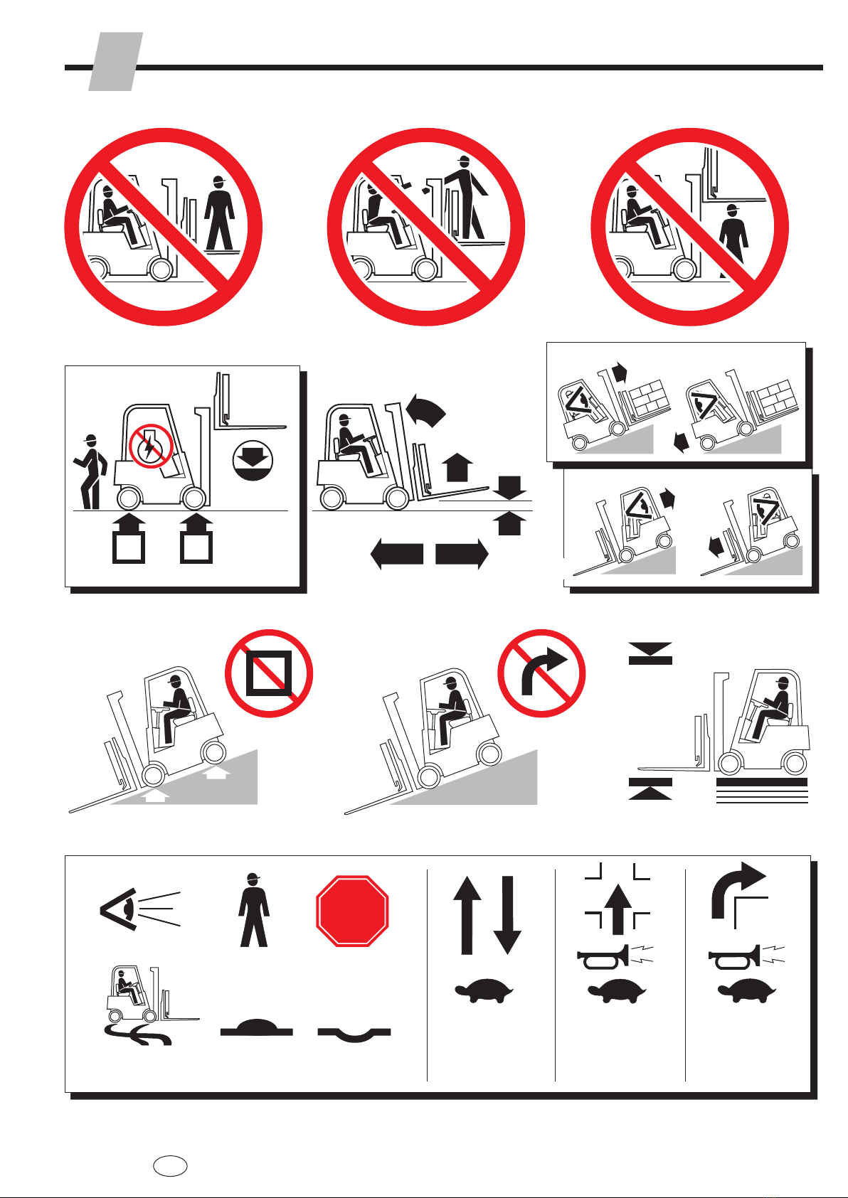
Safety Rules 1
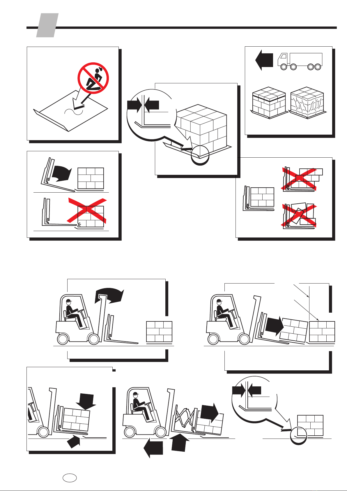
Daily Inspection 2
Attachment Operation 2
Slipsheet Loads 3
Loads with Torn Slipsheet Tabs 3
Loading 4
Loading from Floor 4
Loading from Pallets 4
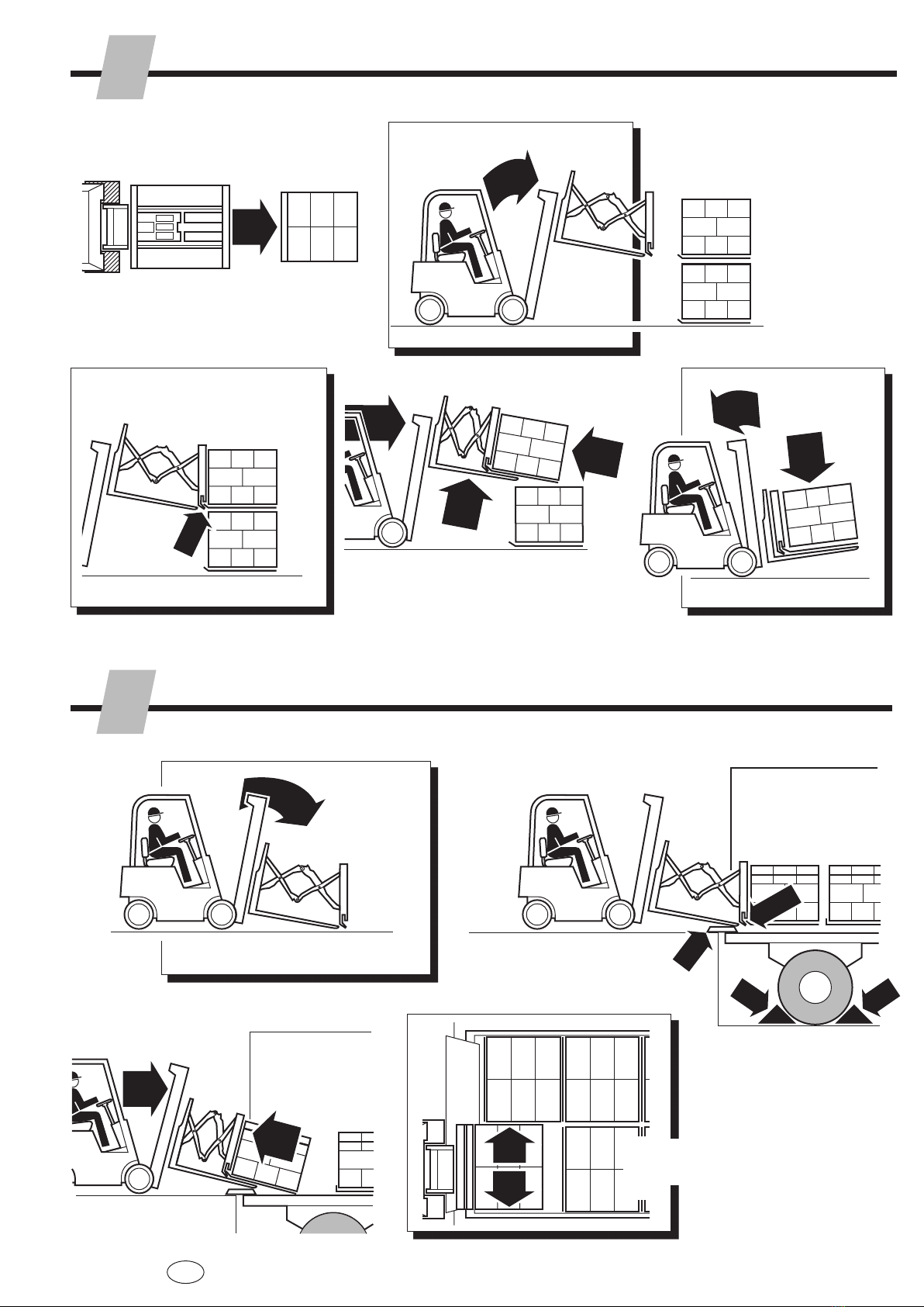
Loading from Stacks 5
Loading from Truck Trailers 5
Unloading 6
Unloading on Stacks 6
Unloading on Pallets 6
Pallet Boards In Line with Push Direction 6
Unloading on Pallets 7
Pallet Boards Opposite Push Direction 7
Unloading into Truck Trailers 7
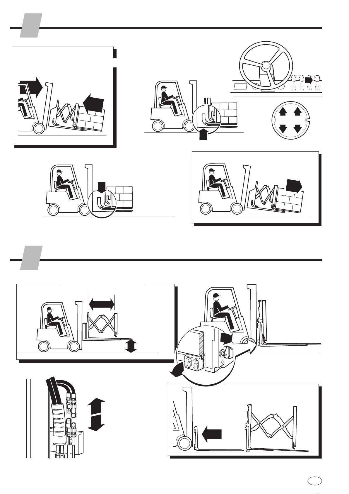
Sheet-Sav® Operation 8
Attachment Removal – QFM™ 8
Attachment Installation – QFM™ 9
Platen Adjustment 9
Faceplate Stop Adjustment 10
Safe Operation and Maintenance 11
OSHA Regulations 11
COntEntS
WARNING: Rated capacity of the truck/
attachment combination is a responsibility
of the original truck manufacturer and may
be less than shown on the attachment
nameplate. Consult the truck nameplate.
WARNING: Do not operate this attachment
unless you are a trained and authorized
lift truck driver.
This guide contains operating instructions for
cascade35E/45E Load Push/Pulls. It will
help avoid common errors which often cause
damage to the equipment or loads being
handled.
Read this manual thourghly before operating
the attachment. Be sure you know and
understand all operating procedures and safety
precautions. If you have any questions or don't
understand a procedure ask your supervisor.
Emphasize Safety! Most accidents are caused
by operator carelessness or misjudgement.
You must watch for hazardous situations and
correct them.
ntrOductiOn
I
Platens
Faceplate
Frame
Platen
Locks
Mechanism
Linkage
Gripper Bar
Gripper Jaw