TABLE OF CONTENTS
GENERAL
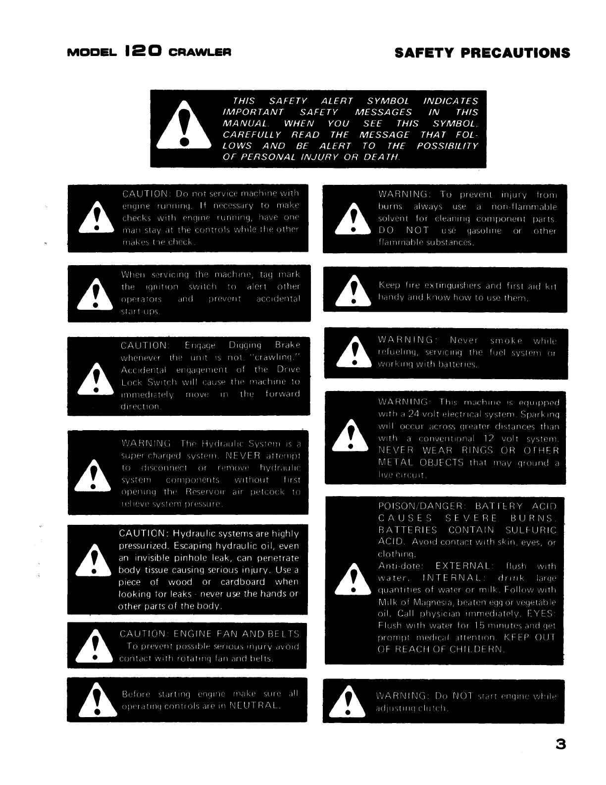
SafetyPrecautions
.............................................................................
3,4
Introduction
.....................................................................................
5
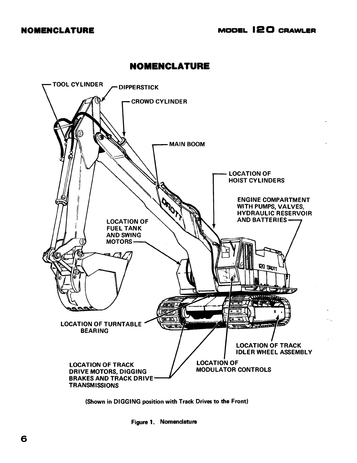
Nomenclatureand MachineGeneral Description
.................................................
6,7
Directional Reference
............................................................................
8
Partsand Service
................................................................................
8
SECTION
1 •
SCHEDULED
PREVENTIVE
MAINTENANCE
Lubricantand Fluid Recommendations
............................................................
9
ComponentCapacities
..........................................................................
10
PressureSettings
...............................................................................
10
MaintenanceSchedule
..........................................................................
11
Service Chart
................................................................................
12,
13
Pictorial Listing
of
Grease
Fitting
Locations
...................................................
14,
15
SECTION
2•
THE
UNDERCARRIAGE
Description, Maintenanceand Troubleshooting
............................................
16 thru
26
Carbodyand Turntable Bearing
................................................................
17
Track Assemblies
......................................................................
18
thru
22
Track Drive Assemblies
................................................................
22
thru
26
Disassemblyand Repair
..................................................................
27
thru
42
General Cleaning Instructions
.................................................................
27
UpperTrack Rollers
........................................................................
28,29
LowerTrack Rollers
........................................................................
30,31
IdlerWheel Assembly
..................................................................
31
thru 33
Digging
Brake
............................................................................
34-35B
Track DriveTransmission
..............................................................
36 thru 42
SECTION
3•
THE
UPPERSTRUCTURE
Description, Maintenanceand Troubleshooting
............................................
43
thru 54
Pump Drive System
....................................................................
43 thru 48
Swing System
.........................................................................
49 thru 53
Boom
Assembly.
. ... . .. .. . .. .. ... .. . .. ... .. . .. ... .. . ... .. .. ... . .. .. . .. . .. .. . ... . . .
..........
54
Disassemblyand
Repair
.
.................................................................
55
thru 67
Pump Drive Transmission and Clutch
...................................................
56 thru 59
House
Brakes
................................................................................
59
Swing Gearbox
........................................................................
59 thru 65
Turntable Bearing Replacement
........................................................
65 thru 67
Boom Removal
..........................................................•....................
67
SECTION
4•
THE
ELECTRICAL
SYSTEM
Description, MaintenanceandTroubleshooting
............•..•.•.............••....•.....•
68 thru
79
The
Charging
System
..................................................................
69thru
74
Control
Circuits
.•........•..............................................•...•...•..•..
74
thru
77
Lightsand Instrument
Circuits
.........................................•......................
78
Disassembly
and
Repair
.
........................................................................
79
1
Find manuals at https://best-manuals.com