GENERAL
TABLE OF CONTENTS
GENERAL
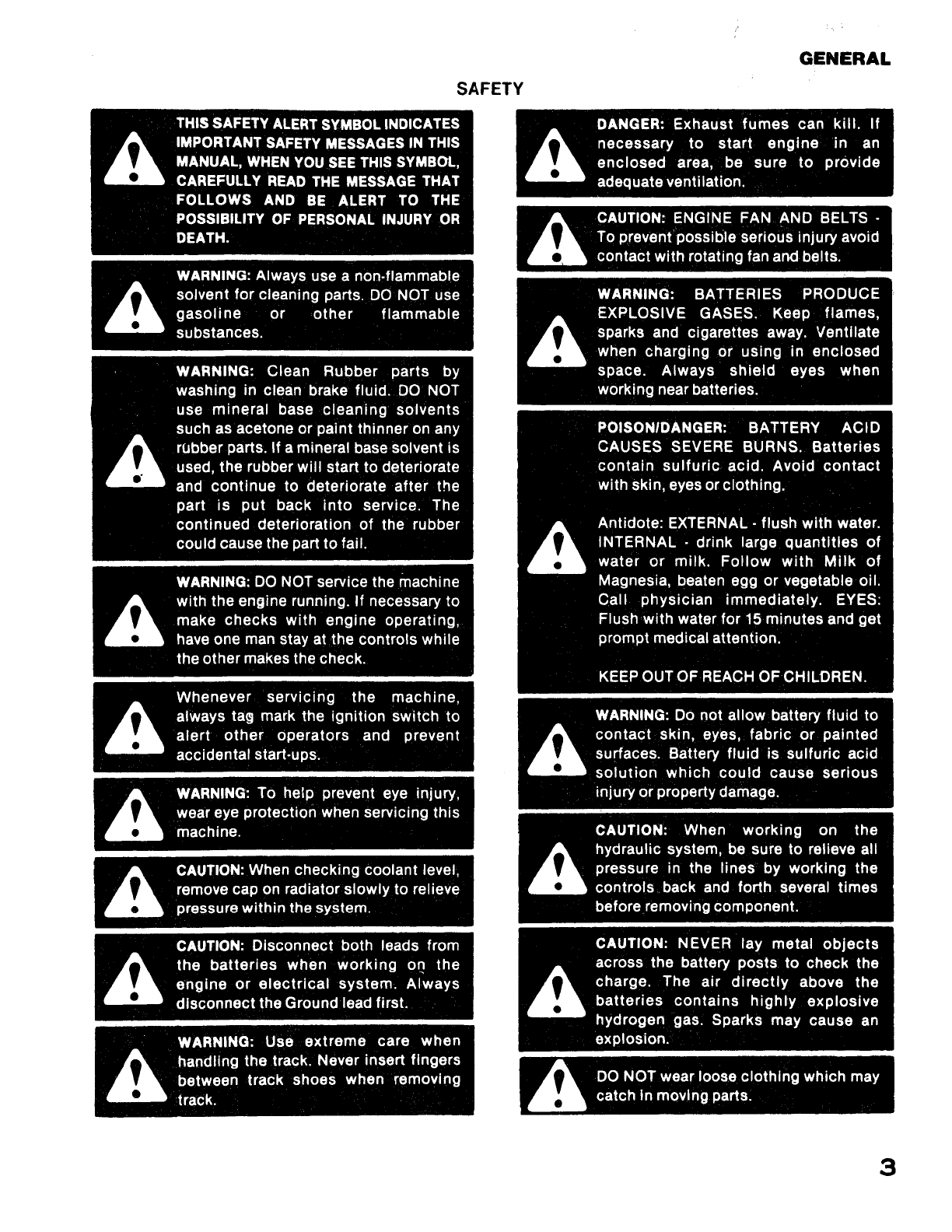
Safety Precautions
...................................................................
3,4
Introduction
..........................................................................
5
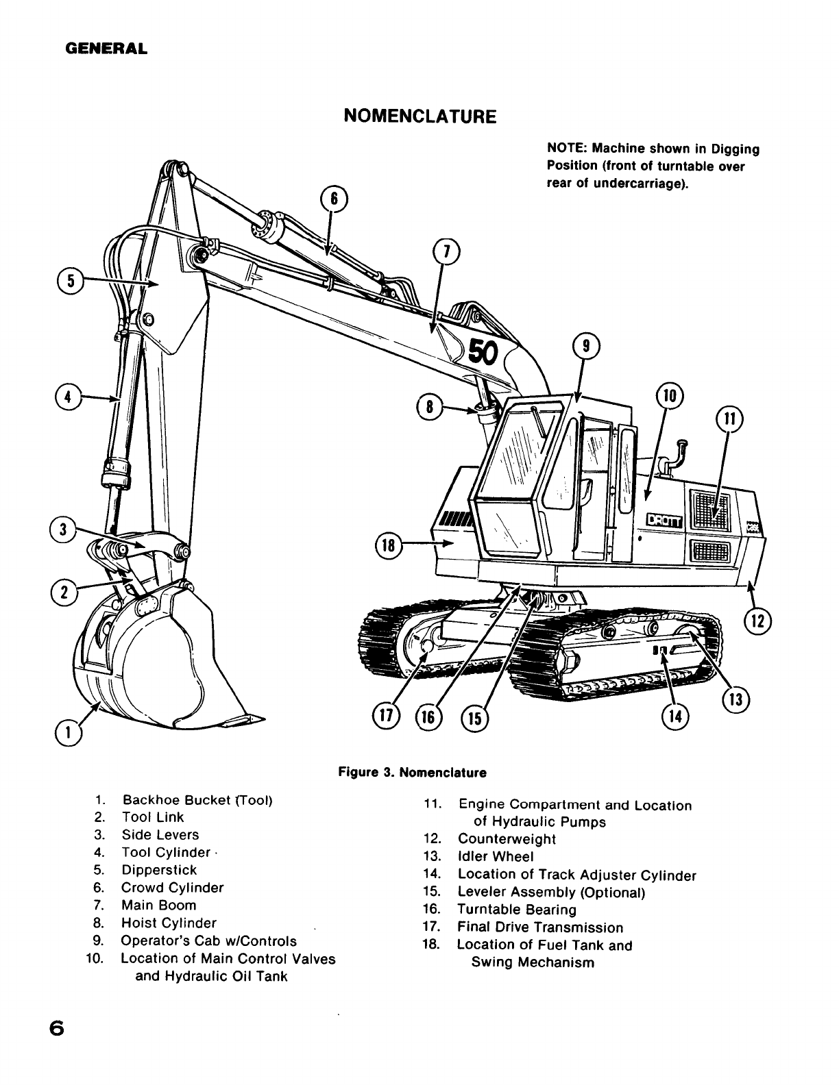
Nomenclatureand General Description
..................................................
6,7
Specifications
........................................................................
8
SECTION 1 • SCHEDULED PREVENTIVE MAINTENANCE
Introduction
..........................................................................
9
Hydraulic Oil Recommendations
........................................................
10
Hydraulic System Operating Pressures
..................................................
10
Component Capacities
................................................................
11
Rated Pump Output
...............................
·
....................................
11
Maintenance Chart
.................................................................
12,
13
Illustrated
Listing
of Grease
Fittings
..................................................
14,15
Itemized Maintenance
Instructions
................................................
16 thru
21
SECTION 2 · MECHANICAL SYSTEM
Undercarriage
.........................
:
.......................................
22
thru
30
Engine and Related Parts
...................................
:
....................
31
thru
34
Turntable Swing
..............
,
.......................
;
.......
,
..........
,
......
34
thru
39
aoom
and
Attachments
........................................
:
................
39
thru
42
SECTION 3 • ELECTRICAL SYSTEM
Introduction
,;
........................................................................
43
12/24 Volt System (Machines through PIN 6280344)
...
,
..............................
44 thru
52
24
Volt System (Machines
with
PIN 6280345 and After)
................................
53
thru
60
Control
Circuits
...
·
...................................................................
61
Lights and Instrumentation
Circuits
.....................................................
62
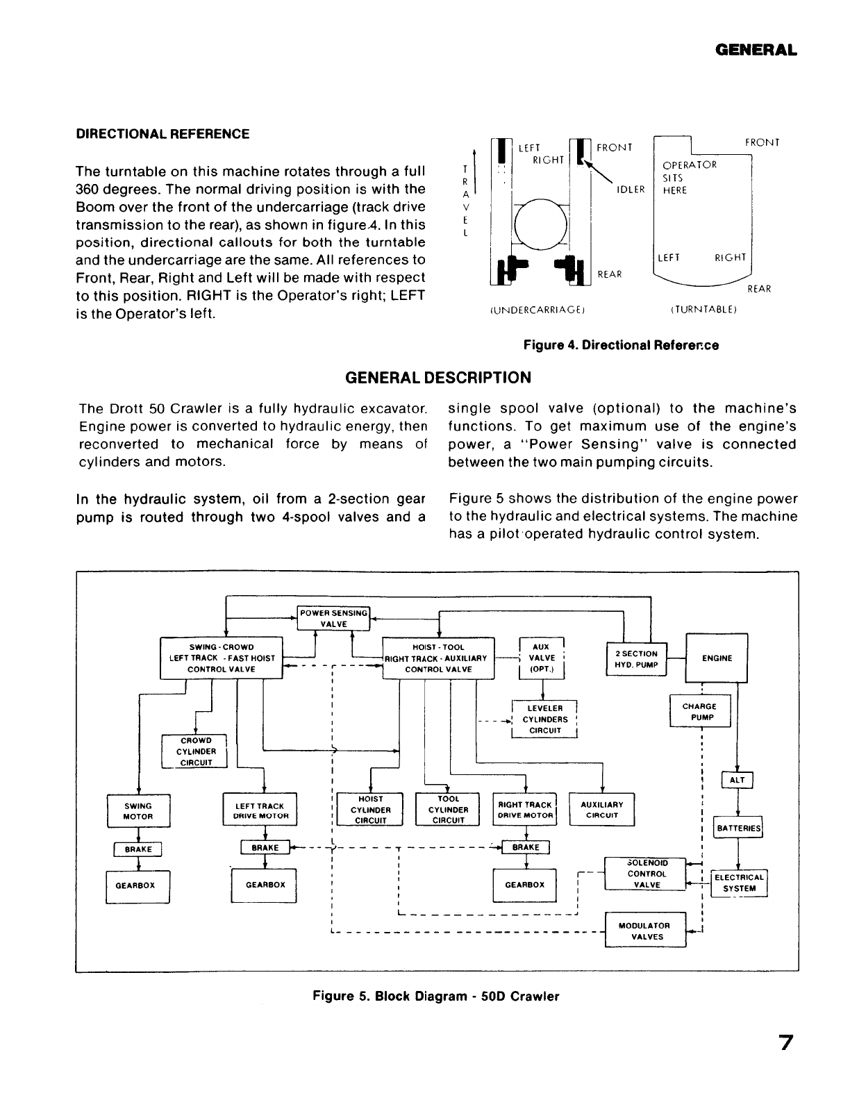
SECTION 4 · HYDRAULIC SYSTEM (For pressures, see page
10)
Introduction
.........................................................................
63
System Maintenance
...........................................................
64
thru
66
Main Hydraulic System
..........................................................
66
thru
80
General Description
.................................................................
66
Hydraulic Pump
....................................................................
68
Main Control Valves
.................................................................
70
Port Relief Valves
...................................................................
73
Explanation
of
"Summated"
System
...................................................
76
Power Sensing Valve
..............................................................
76
Main Relief Valves
................................................................
78
Track Drive Hydraulics
..........................................................
81
thru
87
Drive
Motor
Circuits
.................................................................
81
Digging Brake Release
Circuit
........................................................
85
Solenoid Control Valve
..............................................................
85
Hydraulic Swivel
...................................................................
86
Swing Hydraulics
.....................................................................
88
Hoist
Hydraulics
.....................................................................
90
Hydraulic
Circuits
to Crowd Cylinderand Tool Cylinder
.....................................
92
Leveler Hydraulics
....................................................................
93
PilotControl System
............................................................
94
thru
97
1
Find manuals at https://best-manuals.com