manuals.online logo
Brands
  1. Home
  2. •
  3. Brands
  4. •
  5. Case
  6. •
  7. Excavator
  8. •
  9. Case CX225 TIER 3 User manual

Case CX225 TIER 3 User manual

Other Case Excavator manuals

Case CX300D User manual

Case

Case CX300D User manual

Case 1150M User manual

Case

Case 1150M User manual

Case CX350C User manual

Case

Case CX350C User manual

Case CX330 TIER III User manual

Case

Case CX330 TIER III User manual

Case CX75SR User manual

Case

Case CX75SR User manual

Case CX240C User manual

Case

Case CX240C User manual

Case CX490D User manual

Case

Case CX490D User manual

Case WX218 User manual

Case

Case WX218 User manual

Case 50 Crawler D Series User manual

Case

Case 50 Crawler D Series User manual

Case CX350D User manual

Case

Case CX350D User manual

Case CX31B User manual

Case

Case CX31B User manual

Case CX460 User manual

Case

Case CX460 User manual

Case WX145 User manual

Case

Case WX145 User manual

Case 580 ck User manual

Case

Case 580 ck User manual

Case March 2014 User manual

Case

Case March 2014 User manual

Case CX490C User manual

Case

Case CX490C User manual

Case CX235C SR User manual

Case

Case CX235C SR User manual

Case CX225SR User manual

Case

Case CX225SR User manual

Case CX130B User manual

Case

Case CX130B User manual

Case CX225SR Operating instructions

Case

Case CX225SR Operating instructions

Case 580N EP User manual

Case

Case 580N EP User manual

Case CX490D User manual

Case

Case CX490D User manual

Case 120 User manual

Case

Case 120 User manual

Case CX33C User manual

Case

Case CX33C User manual

Popular Excavator manuals by other brands

jcb JC160 Quick reference guide

jcb

jcb JC160 Quick reference guide

Hyundai Robex 210LC-9 Service manual

Hyundai

Hyundai Robex 210LC-9 Service manual

Hitachi Zaxis 110 Zaxis 125US Workshop manual

Hitachi

Hitachi Zaxis 110 Zaxis 125US Workshop manual

sennebogen 830 E operating instructions

sennebogen

sennebogen 830 E operating instructions

Topcon X-63 Installation and Calibration Manual

Topcon

Topcon X-63 Installation and Calibration Manual

Hitachi ZX27U-2 Operator's manual

Hitachi

Hitachi ZX27U-2 Operator's manual

jcb 15c-1 quick start guide

jcb

jcb 15c-1 quick start guide

Super Products MUD DOG 700 Operator's manual

Super Products

Super Products MUD DOG 700 Operator's manual

Komatsu ecot3 WA200-6 Shop Manual

Komatsu

Komatsu ecot3 WA200-6 Shop Manual

New Holland E57C Service manual

New Holland

New Holland E57C Service manual

Hyundai Robex 160LC-9 Operator's manual

Hyundai

Hyundai Robex 160LC-9 Operator's manual

Doosan DX180LC Shop Manual

Doosan

Doosan DX180LC Shop Manual

Yanmar ViO80-1A USER OPERATION AND MAINTENANCE MANUAL

Yanmar

Yanmar ViO80-1A USER OPERATION AND MAINTENANCE MANUAL

Bush Hog TOUGH BH850 Specifications

Bush Hog

Bush Hog TOUGH BH850 Specifications

Kobelco SK210LC manual

Kobelco

Kobelco SK210LC manual

Hitachi EX1900-6 Technical manual

Hitachi

Hitachi EX1900-6 Technical manual

TATU Marchesan RTA 6 instruction manual

TATU

TATU Marchesan RTA 6 instruction manual

NPK Genesis GHG 16 Safety & operator manual

NPK

NPK Genesis GHG 16 Safety & operator manual

manuals.online logo
manuals.online logoBrands
  • About & Mission
  • Contact us
  • Privacy Policy
  • Terms and Conditions

Copyright 2025 Manuals.Online. All Rights Reserved.

CX225
TIER 3
EXCAVATOR
OPERATOR’S MANUAL
READ, UNDERSTAND, AND FOLLOW ALL SAFETY
PRECAUTIONS AND INSTRUCTIONS FOUND IN THIS
MANUAL BEFORE OPERATINGTHE MACHINE.
Bur • Issued 01Feb 08
Printed in U.S.A. • Book/Form Number 87490340 NA
Copyright © 2007. CNH America, LLC. All Rights Reserved.
TECHNICAL MANUALS
Manuals are available from your Dealer for the operation, service, and repair of your machine.
Contact your Dealer for assistance in obtaining the manuals for your machine.Your Dealer can expedite your order for
Operator’s Manuals, Parts Catalogs, Service Manuals, and maintenance records.
Always give the Machine Name, Model, and P. I.N. (Product Identification Number) or S. N. (Serial Number) of your
machine so your Dealer can provide the correct manuals for your machine.
THIS SAFETY ALERT SYMBOL INDICATES IMPORTANT SAFETY MESSAGES IN THIS MANUAL.
WHENYOU SEE THIS SYMBOL, CAREFULLY READTHE MESSAGETHAT FOLLOWS AND BE ALERT
TO THE POSSIBILITY OF DEATH OR SERIOUS INJURY.
Safety Decals on this machine use the words Danger, Warning, or Caution, which are defined as follows:
●DANGER: Indicates an immediate hazardous situation that, if not avoided, will result in death or serious injury.
The color associated with Danger is RED.
●WARNING: Indicates a potentially hazardous situation that, if not avoided, could result in death or serious
injury. The color associated with Warning is ORANGE.
●CAUTION: Indicates a potentially hazardous situation which, if not avoided, may result in minor or moderate
injury. It may also be used to alert against unsafe practices. The color associated with Caution is YELLOW.
If Safety Decals on this machine are ISO two panel Pictorial, decals are defined as follows:
●The first panel indicates the nature of the hazard.
●The second panel indicates the appropriate avoidance of the hazard.
●Background color is YELLOW
●Prohibition symbols such as and if used, are RED.
STOP
IMPROPER OPERATION OF THIS MACHINE CAN CAUSE DEATH OR SERIOUS INJURY. BEFORE USING THIS
MACHINE, MAKE CERTAIN THAT EVERY OPERATOR:
❷
Is instructed in safe and proper use of the machine.
❷
Reads and understands the Manual(s) pertaining to the machine.
❷
Reads and understands ALL Safety Decals on the machine.
❷
Clears the area of other persons.
❷
Learns and practices safe use of machine controls in a safe, clear area before operating this machine on a job
site.
It is your responsibility to observe pertinent laws and regulations and follow instructions on machine operation and
maintenance.
CALIFORNIA
PROPOSITION 65 WARNING
Diesel engine exhaust and some of its constituents are known to the State of California to cause cancer, birth defects,
and other reproductive harm.
Battery post, terminals and related accessories contain lead and lead compounds. Wash hands after handling.
87490340 NACX225 Tier 3 Excavator
01Feb 08
First Edition
REVISION HISTORY
RemarksIssue Issue Date Applicable Machines
Any use of editorial or pictorial content is strictly prohibited without express written permission from
CNH America, LLC. Racine, WI 53403 U.S.A..
CNH America, LLC reserves the right to make improvements in design or changes in specifications at any time without incurring any
obligation to install them on units previously sold.
All data given in this publication is subject to production variations. Dimensions and weights are only approximate. Illustrations do not
necessarily show products in standard condition.For exact information about any particular product, please consult your Dealer
Find manuals at https://best-manuals.com
0-1
To the Owner
Your machine has been designed and built to the highest standards of quality. It conforms to all current safety
regulations. See “Official documents”. However, the risk of accidents can never be completely excluded. That
is why it is essential to observe elementary safety rules and precautions.
Read this manual carefully, paying particular attention to the instructions concerning safety, operation and
maintenance so as to avoid the risk of injury while operating or servicing the machine.
Use this manual as a guide. Your machine will remain a reliable working tool provided it is kept in good working
condition and serviced properly.
The standard attachments and equipment available for use with this machine are intended for general earth-
moving purposes, material rehandling, boring, ditch cleaning, etc. If the machine is to be used for handling
loads, (concrete pipe sections, shoring material, etc.), make sure the machine is suitably equipped for this type
of work. For this type of application, the machine must be equipped with safety valves, an overload indicator,
a load handling chart corresponding to the type of machine and its attachment and a load fixing point. All legal
requirements must also be strictly observed.
Do not use this machine for any application or purpose other than those described in this manual. If the
machine is to be used for work involving the use of special attachments, accessories or equipment, consult
your CASE Dealer in order to make sure that any adaptations or modifications made are in keeping with the
machine’s technical specifications and with prevailing safety requirements.
Any modification or adaptation which is not approved by the manufacturer may invalidate the machine’s initial
conformity with safety requirements.
The machine must undergo regular inspections, the frequency of which varies according to the type of use.
Consult your CASE Dealer.
Before permitting a new operator on this machine, make sure:
1. That the operator has received the necessary training on how to operate the machine correctly and safely
in one of our training centers or from an approved organization.
2. That the operator has read and understood the instructions given in this manual.
Always keep this manual in the operator’s compartment (in the seat back, behind the operator’s seat). Make
sure it is always complete and in good condition. If you wish to obtain additional manuals, or manuals in another
language, consult your CASE Dealer.
Your CASE Dealer is at your disposal for any further information. He will also provide any after-sales service
you may require, and genuine CASE spare parts, your guarantee of quality and match.
E2440
Find manuals at https://best-manuals.com
0-2
Safety Labels
RIGHT, LEFT, FRONT AND REAR OF THE MACHINE
The terms “Right”, “Left”, “Front” and “Rear” are used in this manual to indicate the sides as they are seen from
the operator’s seat when the cab is over the idler wheels.
The illustration below shows the machine in normal TRAVEL position. In normal TRAVEL position, the cab is
over the idler wheels. The travel reduction gears are at the rear of the upperstructure.
Break-in
This product is shipped after full inspections and conditioning, however, extremely overloaded usage at the
initial stage could lead the reduction in performance and life. Therefore, approx. initial 100 hours (indicated
hours on the service meter) break-in is neccessary.
Break-in should be conducted paying attention to the following points:
• Try to keep idling and warming for 5 minutes after starting the engine.
• Avoid operation under heavy load or at high speeds.
• Avoid any sudden start, acceleration or unnecessary sudden stop and quick turn.
Specified Work
This product is designed to use mainly in the following work:
• Excavation
• Land granding work
• Trenching work
• Loading work
• Demolition (Demolition specification vehicle only)
1FRONT 4LEFT-HAND SIDE
2REAR 5TRAVEL REDUCTION GEARS
3RIGHT-HAND SIDE 6IDLER WHEELS
①
②
③
④
⑤⑤
⑥
⑥
0-0166E
Find manuals at https://best-manuals.com
0-3
For Safe Driving
IMPORTANT:
Remove the protective (rust preventative) aluminum cover wrapped around the cylinder rods immedi-
ately after receiving the machine. If the machine is left with the covers on, water can collect on the
inside of the cover, which will be the cause for rust to develop on the cylinder rod.
In the case of transportation by sea, sea water salt adheres to the machine making rust easier to
develop. Immediately follow the measures below after receiving a machine that has been transported
by sea. If the measures are not taken, the machine will develop rust easily.
1. Confirm that there are no salt deposits on the
machine exterior. When salt deposits are sus-
pected, wash the entire machine with water.
2. Performing Rust Prevention Operation.
1Set the engine at low~medium rpm and go
through the warming up operation.
2Slowly operate each cylinder of the front attach-
ment five strokes each.
3. If Storage Is To Be Continued
[Storage procedures for rust prevention.]
1Grease up each part of the attachment.
(1) Once a week operate each motion (attachment,
swing, travel) with no load which performs rust
prevention operation.
1Put the engine in low~medium rpm and perform
the warming up operation.
2Slowly operate each cylinder of the front attach-
ment five strokes each.
(1) Place each cylinder in the most retracted posi-
tion and apply anti-rust oil to the exposed cylin-
der rod.
(2)
Perform rust-prevention operation once a month.
1Before performing the rust-prevention opera-
tion, remove the anti-rust oil (wipe off with kero-
sene, etc.).
2Afterfinishing therust prevention operation,fully
retract each cylinder and apply anti-rust oil to
the exposed cylinder rod.
CAUTION
Do not use high pressure cleaning water
directly on the alternator, battery and other
electrical parts or wiring.
CAUTION
Start the engine after you understand the oper-
ation methods.
0-0002E
0-0003E
Storage for up to one month
Storage for more than one month
0-0004E
E0040
Find manuals at https://best-manuals.com
0-4
For Safe Driving
SAFETY INSTRUCTIONS
Your safety and that of people around you depend
on you. It is essential that you understand this man-
ual for the correct operation, inspection, lubrication
and maintenance of this machine.
Read this manual carefully and check that :
- You understand fully the symbols on the controls
and the safety signs used in this manual and on the
machine.
- You understand fully the speed, stability, braking
and stability, braking and steering characteristics of
the machine. If you are in any doubt, consult your
CASE Dealer.
The safety messages in this manual concern situa-
tions which may arise during normal machine oper-
ation and servicing. These safety messages also
indicate the different ways of coping with these situ-
ations. Other safety messages are used throughout
the manual to indicate specific dangers.
Whatever type of work is being done (earthmoving,
handling, drilling, etc.), the safety measures for pri-
vate or public work-sites are those which conform to
current regulations in the country concerned, or the
type of operation concerned (mining, quarrying, tun-
nelling).
The safety instructions given in this manual are a
summary of the basic rules to be respected at all
times and do not exempt you from insurance
requirements or from abiding by the highway code.
Always keep this manual in the storage compart-
ment “Pocket” provided for it. Make sure it is always
complete and in good condition.
Pocket
0-0137E
Find manuals at https://best-manuals.com
0-5
For Safe Driving
Warranty
In case faults occur to the machine, the warranty is valid within the range described in the warranty document.
Model and Serial number of manufacture
When ordering parts, obtaining information or assistance, always supply your CASE dealer with the type and
serial number of your machine or accessories.
Write the following in the spaces below: The model number, serial number and year of manufacture of your
machine, accessories and the serial number of the various hydraulic and mechanical components.
Machine
Excavator Identification ___________________________________________________________________
Model Number _________________________________________________________________________
Serial Number __________________________________________________________________________
Engine
Make and type _________________________________________________________________________
Serial number __________________________________________________________________________
Component serial numbers
Hydrauric pump _________________________________________________________________________
Swing reduction gear ____________________________________________________________________
Travel reduction gears ___________________________________________________________________
Travel control valve ______________________________________________________________________
Attachment control valve __________________________________________________________________
Swing control valve ______________________________________________________________________
0-0138E 3-0016E
KHP10690-00
CNH America LLC
Type
Racine, WI 53404 U.S.A
Made in Japan
Find manuals at https://best-manuals.com
0-6-1
Table of Contents
To the Owner ..................................................... 0-1
Safety Labels .....................................................0-2
For Safe Driving.................................................0-3
Safety Section.....................................0-7
Precaution Identification Plates (DECALS)........0-8
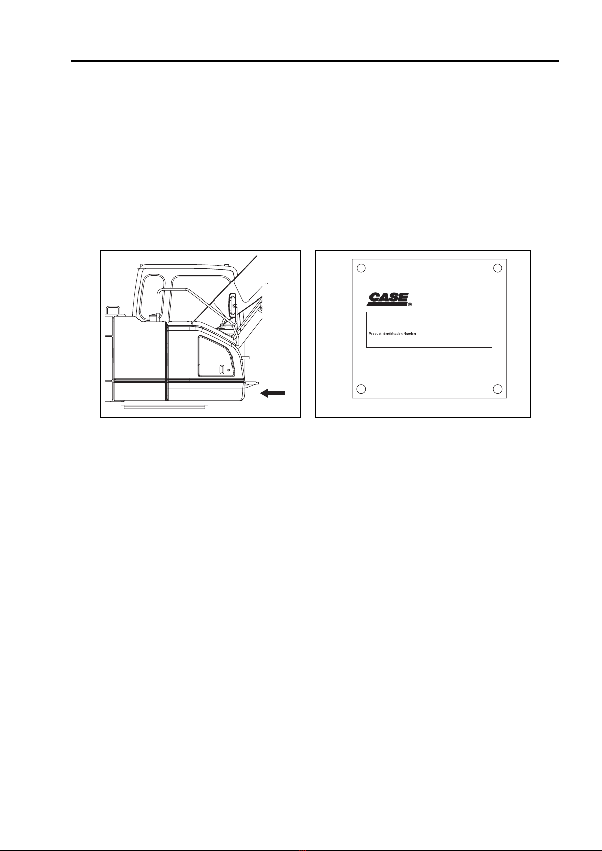
Identification Plates inside the Cabin.......................0-8
Outside Identification Plate....................................0-13
Precaution Identification Plates on Parts (Examples)
...........................................................................0-17
Prior to Operation.............................................0-18
Confirmation of Safety items............................0-20
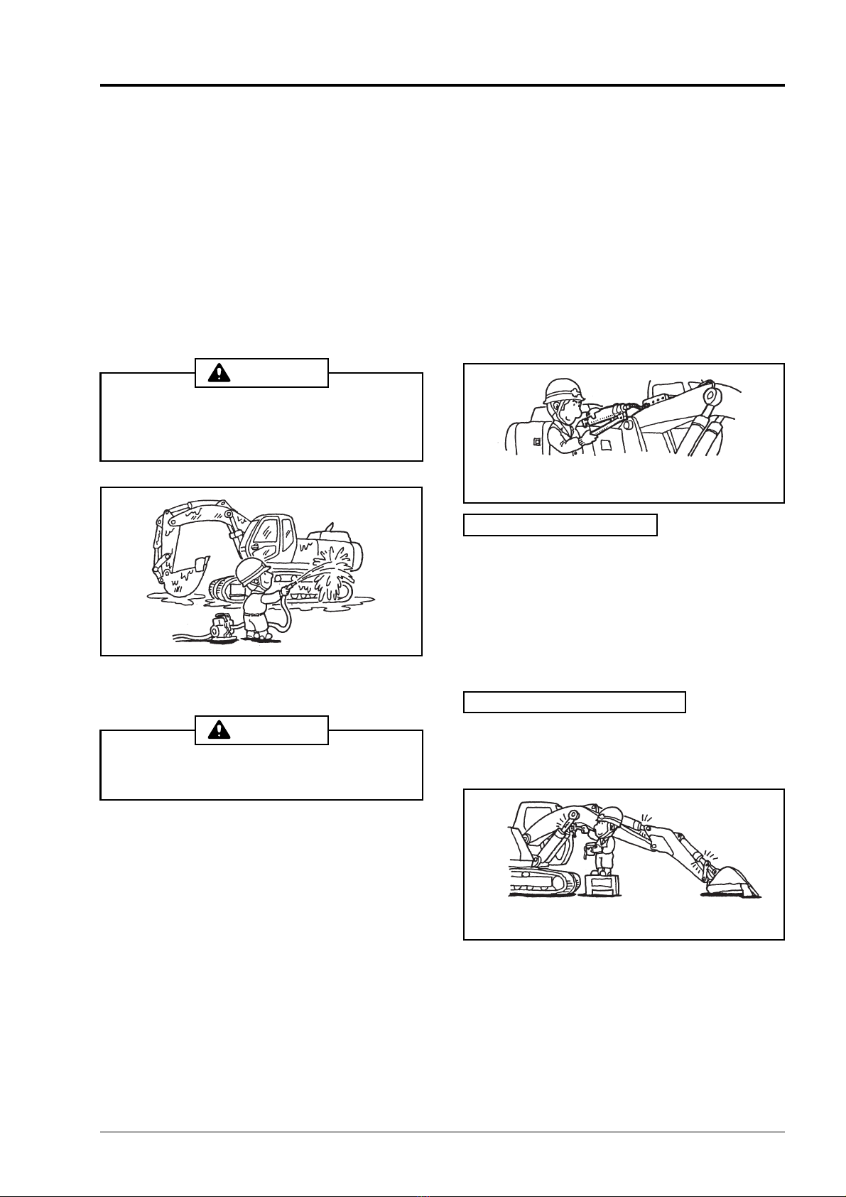
During Operation..............................................0-23
While Traveling ................................................0-27
After Operating.................................................0-28
While Transporting........................................... 0-29
Before Regular Inspection & Maintenance.......0-30
Inspection and Maintenance............................ 0-31
Instruments and Controls..................1-0
Location of Components ....................................1-1
Overall View ............................................................1-1
Operator’s Cab........................................................1-2
Right Console.....................................................1-4
Right Console..........................................................1-4
Monitor & Switch Panel......................................1-5
Monitor & Switch Panel ...........................................1-5
Moniter Display ..................................................1-6
Switch Panel ......................................................1-7
Left Console.......................................................1-9
Left Console ............................................................1-9
Switch....................................................................1-10
Air Conditioner .................................................1-11
Air Conditioner (If equipped)..................................1-11
Explanation of device.......................................1-13
Radio.....................................................................1-13
Operation Levers..............................................1-15
Operation Levers...................................................1-15
Operator’s Seat................................................ 1-18
Operator’s Seat .....................................................1-18
Operator’s Cab.................................................1-20
Fuses ...............................................................1-22
Fuses.....................................................................1-22
Explanation of device.......................................1-23
Battery...................................................................1-23
Starting the Engine by Using Booster Cables .......1-24
Operating Instructions.......................2-0
Operation of New Machine.................................2-1
Using a New Machine..............................................2-1
Daily Inspections................................................2-2
Daily Inspections .....................................................2-2
Starting and Stopping the Engine ......................2-4
Inspections before Starting the Engine....................2-4
Starting the Engine..................................................2-5
Inspections after Starting the Engine.......................2-6
Stopping the Engine (Normal Operation) ................2-7
Warm-up Operation............................................2-8
Warm-up Operation................................................. 2-8
Operations (Traveling)......................................2-10
Operations (Swing)...........................................2-19
Swing Operation....................................................2-19
Operations (Attachment) ..................................2-20
Operations (Attachment).......................................2-20
Operations........................................................2-21
Blade Operation ....................................................2-21
Characteristics of Hydraulic Excavator..................2-21
Cautions for operations.........................................2-22
Cautions for Interference.......................................2-22
Operating Instructions (Cautions).....................2-24
Operating Instructions (Procedures) ................2-25
Bucket: Turning Over and Replacement..........2-27
Bucket: Turning Over and Replacement...............2-27
On Completion of Daily Operations..................2-29
On Completion of Daily Operations.......................2-29
Operating in Cold Climates ..............................2-31
Operating under Extreme Conditions...............2-32
Transportation..................................................2-33
Loading and Unloading ......................................... 2-33
Switch settings during loading and unloading.......2-33
Transportation.......................................................2-33
Storing..............................................................2-37
Inspections and Maintenance............3-0
General Cautions ...............................................3-1
Periodic Maintenance Check List.......................3-2
Daily Inspections (Prior to Operation) .....................3-2
Periodic Maintenance Check List............................ 3-3
Fuel / Lubricants for Different Ambient Temperature
Settings ............................................................... 3-4
Genuine CASE Company LLC Parts and Elements 3-5
Disposable Items.....................................................3-6
Grease / Oil and Elements.................................3-7
Inspection Prior to Operation..............................3-9
Inspections Prior to Operation.................................3-9
Greasing Attachments......................................3-13
Greasing Front Attachment Pins ...........................3-13
Fuel System .....................................................3-15
Fuel .......................................................................3-15
Fuel Refilling and Fuel Level Checking.................3-18
Drainage of Water and Sediments in the Fuel Tank
..........................................................................3-18
Draining Water from the Pre Fuel Filter.................3-19
Pre Fuel Filter Replacement..................................3-20
Draining Water from the Fuel Filter (Main)............3-21
Fuel Filter (Main) Replacement.............................3-21
Engine..............................................................3-23
Engine Oil Replacement........................................ 3-23
Engine Oil Filter Replacement...............................3-23
Cooling System.....................................................3-25
Inspecting and Refilling Coolant............................3-25
Replacing the Coolant...........................................3-26
Cleaning and Inspecting the Radiator Net and Fin
..........................................................................3-27
Cleaning and Replacing the Air Cleaner (double ele-
ments) ...............................................................3-28
Inspection and Adjustment of Fan Belt..................3-30
Find manuals at https://best-manuals.com
0-6-2
Table of Contents
Bolt Torque ...................................................... 3-31
Bolt and Nut Torque.............................................. 3-31
Hydraulic Oil..................................................... 3-34
Hydraulic Oil Level Inspection............................... 3-34
Refilling Hydraulic Oil............................................ 3-34
Draining Water and Sediment from the Hydraulic Oil
Tank.................................................................. 3-35
Hydraulic Oil Management.................................... 3-36
Hydraulic Oil Replacement.................................... 3-36
Bleeding Air from the Hydraulic Components ....... 3-37
Air Bleeding Procedures ....................................... 3-37
Air Bleeding from Hydraulic Pump........................ 3-37
Air Bleeding from Cylinder .................................... 3-38
Air Bleeding from Swing Motor.............................. 3-38
Cleaning and Replacing Suction Filter.................. 3-39
Replacing Return Filter ......................................... 3-39
Replacing Air Breather Element............................ 3-40
Replacing Pilot Oil Filter Element.......................... 3-40
Replacement Intervals for Hydraulic Oil and Filters when
Using Breaker
..................................................... 3-41
Checking Hoses and Lines ................................... 3-41
Battery.............................................................. 3-42
Battery Inspection and Charge.............................. 3-42
Upper Frame.................................................... 3-44
Turntable Bearing Greasing.................................. 3-44
Greasing Swing Ring Gear ................................... 3-44
Swing Unit........................................................ 3-45
Oil Level Inspection and Refilling of Swing Reduction
Gear.................................................................. 3-45
Oil Replacement for Swing Reduction Gear ......... 3-45
Greasing Swing Reduction Gear........................... 3-46
Travel Unit........................................................ 3-47
Travel Reduction Gear.......................................... 3-47
Oil Level Inspection and Refilling of Travel Reduction
Gear.................................................................. 3-47
Oil Replacement for Travel Reduction Gear......... 3-47
Inspecting Upper/Lower Take-up Roller (Idler Wheel)
.......................................................................... 3-48
Inspection and Tightening of Shoe Plate .............. 3-48
Cleaning Crawler................................................... 3-48
Inspection and Adjustment of Track Shoe Tension
.......................................................................... 3-49
Bucket.............................................................. 3-50
Replacing Bucket Teeth: Standard type (Length Pin
Type)................................................................. 3-50
Replacing Bucket Tooth: Standard type (Side pin type)
.......................................................................... 3-52
Replacing Bucket Teeth: Heavy Digging Type...... 3-53
Adjustment of Bucket Backlash............................. 3-54
Air Conditioner ................................................. 3-55
Inspection and Care of Air Conditioner (If Equipped)
.......................................................................... 3-55
Routine Replacement Safety Parts.................. 3-59
Troubleshooting ............................................... 3-60
Contacting Us .................................................. 3-65
Specifications......................................4-0
Conversion Factors............................................ 4-1
CONVERSION FACTORS...................................... 4-1
Specifications..................................................... 4-2
CX225SR.................................................................4-2
CX225SR (with BLADE) ........................................4-13
Optional Components........................5-0
Breakers............................................................. 5-1
Handling the Breaker (Attachment)..........................5-1
When Using a Hydraulic Breaker.............................5-2
Operating the breaker..............................................5-4
Importance of Hydraulic oil Control..........................5-5
Crusher .............................................................. 5-7
Using the Crusher (Attachment) ..............................5-7
Load Lifting Operation...................................... 5-10
Find manuals at https://best-manuals.com