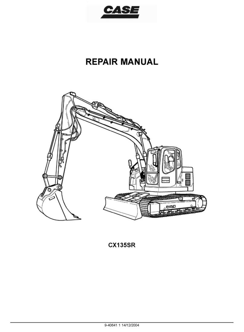
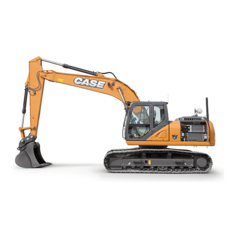
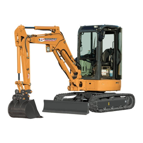
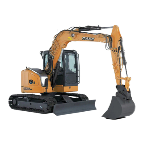
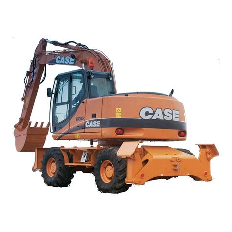
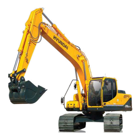
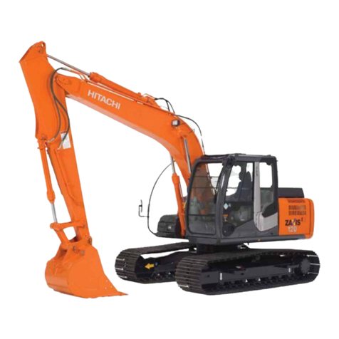
Case 788 User manual

Copyright 2000 Case France
Printed in France
Case Cre 7-58655GB March 2000
788/988 - 788/988 Plus Crawler Excavators
788/988 - 788/988 Plus Wheeled Excavators
Table of Contents
DIVISION/SECTION SECTION N°REFERENCE N°
1 GENERAL INFORMATION
Safety, general and torque settings .................................................................1001 7-56942GB
Specifications (Crawler excavators).................................................................1002 7-80071GB
Specifications (Wheeled excavators)...............................................................1002 7-80062GB
2ENGINE
Engine removal and installation (788 - 988 - 988 Plus ....................................2002 7-58681GB
Engineremoval and installation(788Plus)......................................................20027-26560GB
Radiator and oil cooler.....................................................................................2003 7-80621GB
Engine specifications .......................................................................................2401 **
Cylinder head and valve assembly..................................................................2415 * *
Engine block ....................................................................................................2425 * *
Lubrication system...........................................................................................2445 * *
Cooling system ................................................................................................2455 * *
Turbocharger....................................................................................................2465 * *
Turbocharger failure analysis...........................................................................2565 * *
3 FUEL SYSTEM
Fuel system and filter.......................................................................................3410 * *
CAV injection pump..........................................................................................3411 * *
BOSCH injection pump....................................................................................3412 * *
Fuel injector .....................................................................................................3412 * *
BOSCH ANEROID fuel injection pump............................................................3416 * *
4 ELECTRICAL SYSTEM
Electrical schematic (Crawler excavators) - (before November 1999).............4001 7-80040GB
Electrical schematic (Wheeled excavators) - (before November 1999)...........4001 7-80021GB
Electrical schematic (Crawler excavators) - (November 1999 and after).........4001 7-26570GB
Electrical schematic (Wheeled excavators) - (November 1999 and after).......4001 7-26540GB
Electronic system and troubleshooting (Crawler excavators)..........................4002 7-80031GB
Electronic system and troubleshooting (Wheeled excavators) ........................4002 7-80051GB
Starter motor....................................................................................................4003 7-58691GB
Alternator .........................................................................................................4004 7-58701GB
Powersensor diagnostic tool............................................................................4010 7-79991GB
5 UNDERCARRIAGE
Track group (Crawler excavators)....................................................................5002 7-58711GB
6 DRIVE TRAIN
Travel reduction gear and brake (Crawler excavators)....................................6002 7-80661GB
Swing reduction gear and brake (788 - 788 Plus)............................................6003 7-80671GB
Swing reduction gear and brake (988).............................................................6003 7-58731GB
Swing reduction gear and brake (988 Plus).....................................................6003 7-84141GB
Front axle and service brake (Wheeled excavators)........................................6004 7-80681GB
Rear axle and service brake (Wheeled excavators) ........................................6005 7-80691GB
Gearbox and parking brake (Wheeled excavators) .........................................6008 7-80701GB
Twin wheels (Wheeled excavators) .................................................................6020 7-26170GB
* * Consult the engine Service Manual.

Cre 7-58655GB Issued 03-00
DIVISION/SECTION SECTION N°REFERENCE N°
7 UNDERCARRIAGE HYDRAULICS
Hydraulic travel motor (Mono-speed crawler excavators)................................7002 7-80711GB
Hydraulic travel motor (Two-speed crawler excavators)..................................7003 7-80721GB
Hydraulic travel motor (Wheeled excavators)..................................................7003 7-80731GB
Travel control valve (Crawler excavators)........................................................7030 7-80741GB
Travel, stabilizer and dozer blade control valve
(wheeled excavators) ..................................................................................7031 7-84151GB
Steering, stabilizer, dozer blade and front axle locking cylinders
(wheeled excavators ) .................................................................................7080 7-84161GB
8 UPPERSTRUCTURE HYDRAULICS
Hydraulic inspection, adjustment and schematics
(crawler excavators) ....................................................................................8001 7-24590GB
Hydraulic inspection, adjustment and schematics
(wheeled excavators) ..................................................................................8001 7-24580GB
Hydraulic swivel (Crawler excavators).............................................................8011 7-80791GB
Hydraulic swivel (Wheeled excavators)...........................................................8011 7-80801GB
Hydraulic pumps (788 - 788 Plus)....................................................................8020 7-80211GB
Hydraulic pumps (988 - 988 Plus)....................................................................8020 7-58862GB
Hydraulic swing pump......................................................................................8021 7-21700GB
Attachment control valve..................................................................................8031 7-80821GB
Swing control valve..........................................................................................8033 7-80831GB
Rotary control valve (Orbitrol) (Wheeled excavators)......................................8037 7-80841GB
Hydraulic swing motor and forced-feed safety block .......................................8040 7-80851GB
Attachment and swing control block ...............................................................8050 7-80261GB
Travel and option control block
(Foot pedal, Wheeled excavators)...............................................................8051 7-80270GB
Travel hand control block (Inching, wheeled excavators)................................8052 7-80870GB
Direction of travel inverter control block (Inching, crawler excavators)............8053 7-80290GB
Travel control block (788 - 788 Plus 988 - 988 Plus wheeled excavators) ......8054 7-80301GB
Brake module (wheeled excavators)................................................................8060 7-80882GB
Parking brake electro-control valve (wheeled excavators) ..............................8061 7-80952GB
Electro-control valve block (Crawler excavators).............................................8070 7-80321GB
Electro-control valve block (wheeled excavators)............................................8071 7-84191GB
Selector block (788 Plus).................................................................................8072 7-26650GB
Attachment cylinders........................................................................................8080 7-84201GB
Safety valve .....................................................................................................8081 7-26640GB

Cre 7-58655GB Issued 03-00
DIVISION/SECTION SECTION N°REFERENCE N°
9 UPPERSTRUCTURE
Upperstructure and turntable bearing ..............................................................9002 7-58932GB
Cab ..................................................................................................................9004 7-58191GB
Large format hydraulic and electrical schematics
(788 crawler excavators) - (before November 1999)................................Pocket 7-80190GB
Large format hydraulic and electrical schematics
(788 wheeled excavators) - (before November 1999)..............................Pocket 7-80200GB
Large format hydraulic and electrical schematics
(988 crawler excavators) - (before November 1999)................................Pocket 7-58980GB
Large format hydraulic and electrical schematics
(988 wheeled excavators) - (before November 1999)..............................Pocket 7-58970GB
Large format hydraulic and electrical schematics
(788 Pus crawler excavators) - (November 1999 and after).....................Pocket 7-26730GB
Large format hydraulic and electrical schematics
(788 Plus wheeled excavators) - (November 1999 and after)..................Pocket 7-26760GB
Large format hydraulic and electrical schematics
(988 Plus crawler excavators) - (November 1999 and after)....................Pocket 7-26770GB
Large format hydraulic and electrical schematics
(988 Plus wheeled excavators) - (November 1999 and after)..................Pocket 7-26780GB


Thanks very much for your reading,
Want to get more information,
Please click here, Then get the complete
manual
NOTE:
If there is no response to click on the link above,
please download the PDF document first, and then
click on it.
Have any questions please write to me:
admin@servicemanualperfect.com

Section
1001
1001
Cre 7-56942GB Printed in France
Case
SAFETY, GENERAL INFORMATION
AND TORQUE SPECIFICATIONS
Copyright © 1999 Case France
Issued November 1999

1001-2
Cre 7-56942GB Issued 11-99
TABLE OF CONTENTS
SAFETY.....................................................................................................................................................................3
TWIN WHEELS.........................................................................................................................................................5
Safety rules ...........................................................................................................................................................5
Safety instructions.................................................................................................................................................5
GENERAL INFORMATION.......................................................................................................................................6
CORRECT USE OF TORQUE WRENCHES............................................................................................................7
HARDWARE TIGHTENING ORDER ........................................................................................................................8
STANDARD SCREW A TORQUE SPECIFICATIONS..............................................................................................9
Correct screw identification...................................................................................................................................9
METAL CAP REFERENCES...................................................................................................................................10
PLASTIC PLUG AND CAP REFERENCE CHART.................................................................................................11

1001-3
Cre 7-56942GB Issued 11-99
SAFETY
To avoid all risks, always follow the safety notes con-
tained in this section and throughout this manual.
Put the warning tag shown below on the key for the
keyswitch when servicing or repairing the machine.
One warning tag is supplied with each machine.
Additional tags, Part Number 321-4614, are available
from your service parts supplier.
PDG0328
WARNING:
This symbol means WARNING ! BE VIGILANT ! YOUR SAFETY IS AT RISK. The message
that follows the symbol contains important safety information. Read it carefully. Be sure you understand
the possible risks of injury or even death.
!
WARNING:
Read the Operator’s Manual
carefully and make sure you understand how
to operate the controls correctly.
WARNING:
Never operate the machine and
attachment controls unless you are seated in
the operator’s seat. If you are not in the
operator’s seat, you run the risk of serious
injury.
WARNING:
The machine is built to carry the
operator only. Do not allow passengers to
ride on the machine.
!
!
!
WARNING :
Prior to starting up the engine
read the safety messages contained in the
operator’s manual carefully. Read all safety
stickers on the machine. Have people move
back from the machine. Learn how to use the
controls before starting up the machine. It is
your responsibility to follow the manufacturer’s
instructions on how to operate and maintain
the machine. It is your responsibility to follow
applicable rules and regulations. Service and
Operator’s Manuals are available from your
J.I. Case Dealer.
WARNING:
If you wear loose clothing or if
you omit to use safety equipment for your
work, you risk injury. Always wear clothes
that do not risk getting caught in the
machine. Other safety equipment may be
necessary, in particular : helmets, safety
shoes, ear plugs, safety glasses, protection
mask, thick gloves and reflecting clothes.
WARNING:
When working close to the fan
with the engine running, avoid wearing loose
clothing and operate with extreme caution.
WARNING:
When checking the hydraulic cir-
cuits, follow procedures to the letter. DO
NOT CHANGE procedures.
!
!
!
!

1001-4
Cre 7-56942GB Issued 11-99
WARNING:
Prior to operating the hydraulic
cylinders of this machine for setting or to
bleed the circuit, have all people standing
around the machine move away.
WARNING:
Wear gloves or insulated mittens
when working on hot parts.
WARNING:
Lower all attachments to the
ground or rest them on stands before carry-
ing out maintenance jobs.
WARNING:
Fine sprays of hydraulic oil
under pressure can penetrate the skin and
cause serious infection. If hydraulic oil under
pressure penetrates the skin, see a doctor
immediately. Maintain all hoses and pipes in
good condition. Make sure that all connec-
tions are properly tightened. Change all
hoses or pipes that have been damaged or
that are suspect. DO NOT CHECK for leaks
with bare hands. Use a piece of cardboard
or wood.
WARNING:
To remove a hardened pin such
as a pivot pin, or a hardened shaft, use a
soft head hammer (brass or bronze) or a
brass or bronze strip and a steel head ham-
mer.
WARNING:
When using a hammer to
remove or reassemble pivot pins, or when
using compressed air, or when using a
grinder make sure to wear safety glasses
that protect the eyes from all sides.
WARNING:
Use proper lifting/hoisting equip-
ment to lift wheels or tracks and always work
on safe ground. Prevent the machine from
moving using correct safety chocks.
!
!
!
!
!
!
!
WARNING:
When performing maintenance
or repair operations on the machine, make
sure that the work shop floor, the cab and
the steps of the excavator are free from oil,
water, grease, tools etc. Use oil absorbing
material or rags as necessary. Always think
safety.
WARNING:
Certain components of this
machine are very heavy. Use hoisting tools
or additionnal assistance as recommended
in this manual.
WARNING:
Exhaust fumes can cause death.
If it is necessary to start up the engine in a
closed building, evacuate exhaust fumes
using an exhaust pipe extension. Open the
doors and let fresh air into the building.
WARNING:
When battery liquid is frozen,
the battery can explode if : (1) you try to
charge the battery or (2) you try to start the
engine by connecting an auxiliary power
source. To prevent battery electrolyte from
freezing keep the battery fully charged. If
you do not follow these instructions, you or
others nearby may be injured.
WARNING:
Batteries contain acid and explo-
sive gases. A spark, a flame or an improper
cable connection may cause an explosion.
For proper connection of cables to the bat-
tery of this machine see the Operator’s Man-
ual. If you do not follow these instructions,
you risk severe injury.
!
!
!
!
!
1001-5
Cre 7-56942GB Issued 11-99
TWIN WHEELS
Safety rules Safety instructions
•Use appropriate, good quality tools to disassemble
the various wheel components. Never use a ham-
mer. Use a rubber, plastic or copper-faced mallet.
IMPORTANT:
Never remove the inner tyre valve
extension, as this will be necessary afterwards for
inflating and deflating the tyre.
IMPORTANT:
If the valve or the valve extension are
no longer accessible, take the necessary precautions
and then, imperatively, puncture the tyre.
•Use suitable grease to facilitate the installation and
removal of the tyre.
•Never re-inflate a tyre on the machine which has
been used at a pressure lower than 5.6 bar.
•Check the various components: tyre, rim, shoulder,
retaining ring and replace any defective items.
•Never reuse a retaining ring which is distorted or
rusty.
WARNING:
In all cases, before removing twin
wheels, always deflate both tyres completely.
WARNING:
If a tyre bursts it can cause seri-
ous injury. Check tyres regularly to see that
they are in good condition and always be sure
to inflate them to the correct pressure.
WARNING:
Never face a tyre when checking
pressure or adding air. Always stand in front of
the tread. Use an inflation cage if the wheel
has been removed from the machine. Make
sure all people standing in the area move well
away.
WARNING:
Never weld near a tyre.If this can
not be avoided, it is mandatory to remove the
tyre before performing any welding operations.
WARNING:
Make sure that all decals on the
machine are perfectly legible, clean them regu-
larly and replace any decals which are dam-
aged, missing or painted over, with new ones.
!
!
!
!
!
1001-6
Cre 7-56942GB Issued 11-99
GENERAL INFORMATION
CLEANING
Clean all metal parts except bearings with white spirit
or steam. Do not use caustic soda when steam
cleaning. After cleaning, dry and lubricate all parts.
Clean hydraulic lines with compressed air. Clean
bearings with kerosene, then dry them and lubricate
them.
INSPECTION
Check all parts when disassembled. Change all parts
showing wear or damage. Scratches that are not too
deep can be removed by honing or with a rag dipped
into buffing compound. A full visual inspection to
detect wear and pitting and subsequent changing of
parts will prevent premature failure.
BEARINGS
Check that bearings rotate freely. If their adjustment
is too loose or if they do not run regularly, change
them. Wash bearings with a good solvent or kero-
sene and let them dry. DO NOT DRY BEARINGS
WITH COMPRESSED AIR.
NEEDLE BEARINGS
Before inserting needle bearings into a bore, remove
all metal particles from the edge of the bore. Prior to
mounting bearings with a press, coat the inside and
the outside of the bearing with vaseline.
GEARS
Check all the gears for wear or damage. Change
worn or damaged gears.
SEAL RINGS, O-RINGS, GASKETS
Always use new seal rings. O-rings and gaskets.
Coat sealing rings and O-rings with vaseline.
SHAFTS
Check all shafts showing signs of wear or damage.
Check that the surface of a shaft running in a bearing
is not damaged.
SPARE PARTS
Always use original CASE spare parts. To order
spare parts, see the Spare Parts Catalogue to indi-
cate the proper reference of original CASE spare
parts. Failures caused by the use of parts that are not
original CASE spare parts are not covered by the
warranty.
LUBRICATION
Use only oils and lubricants specified in the Opera-
tor’s and Service Manuals. Failures due to the use of
oils and lubricants not specified are not covered by
the warranty.

1001-7
Cre 7-56942GB Issued 11-99
CORRECT USE OF TORQUE WRENCHES
TORQUE
WRENCHES
PDG0315
CORRECT USE
a - Hold the wrench by the handle
provided.
b - When tightening, always keep the
wrench perpendicular to the screw.
c - Keep one hand on the leverage
point handle on the wrench.
d - Tighten progressively in one
movement.
e - Position a correctly dimensioned
socket or open-ended wrench on the
flats of the screw head.
PDG0316
Open-ended wrench
Manipulator
Leverage point handle
1/2” square insert
Setting pointer Adjusting lever
Extension SJ214, for doubling
capacity of S203 wrenches
NO
NO
HAND
NO

1001-8
Cre 7-56942GB Issued 11-99
HARDWARE TIGHTENING ORDER
TORQUE
WRENCHES
PDG0317
INITIAL TORQUE
a - Torque wrench.
- Follow the correct order of proce-
dure when tightening.
- Cross or diagonal pattern tightening.
PDG0318
FINAL TORQUE
Always tighten in clockwise order.
PDG0319

1001-9
Cre 7-56942GB Issued 11-99
STANDARD SCREW A TORQUE SPECIFICATIONS
Correct screw identification
Zinc bichromate
Phosphate
Diameter x
thread size
Grade 8.8
Key
Torque
Nm lb.ft
Two-part hydraulic connector
(to SAE J518 specifications)
PDG0321
Components assembled by
screws and bolts
SCREW
BOLT
PDG0322
M5 x 0.8
M6 x 1
M8 x 1.5
M10 x 1.5
M12 x 1.75
M14 x 2
M16 x 2
M18 x 2.5
M20 x 2.5
M22 x 2.5
M24 x 3
M27 x 3
M30 x 3.5
4
5
6
8
10
12
14
14
17
17
-
-
-
8
10
13
17
19
22
24
27
30
32
36
41
46
5.5
9
22.5
45
70
100
170
250
350
500
600
900
1200
5.5
9
22.5
45
80
120
200
300
400
600
700
1000
1400
4.1
6.7
16.6
33.2
51.6
73.8
125.5
184.5
258.3
369
442.8
664.2
885.6
4.1
6.7
16.6
33.2
59
88.6
147.6
221.4
295.2
442.8
516.6
738
1033.2
Grade 10.9
M5 x 0.8
M6 x 1
M8 x 1.5
M10 x 1.5
M12 x 1.75
M14 x 2
M16 x 2
M18 x 2.5
M20 x 2.5
M22 x 2.5
M24 x 3
M27 x 3
M30 x 3.5
4
5
6
8
10
12
14
14
17
17
-
-
-
8
10
13
17
19
22
24
27
30
32
36
41
46
75
12.5
35
60
100
170
250
350
500
700
900
1200
1700
75
12.5
35
70
120
200
300
400
600
800
1000
1400
1900
5.6
9.3
25.8
44.3
73.8
125.5
184.5
258.3
369
516.6
664.2
885.6
1254.6
5.6
9.3
25.8
51.6
88.6
147.6
221.4
295.2
442.8
442.8
738
1033.6
1402.2
PDG0320
Steel grade Steel grade

1001-10
Cre 7-56942GB Issued 11-99
METAL CAP REFERENCES
To SAE J518 specifications
NP = Nominal pressure
NP = Nominal diameter
NP 250 bar
Ø ND NP 400 bar
Ø ND Part number
AB
PDG0323
13 mm
19 mm
25 mm
32 mm
38 mm
-
-
-
-
-
-
-
-
-
13 mm
19 mm
25 mm
32 mm
D5327838
F5327840
H5327842
K5327844
M5327846
U5327830
W5327832
Z5327834
B5327836
E5327839
G5327841
J5327843
L5327845
N5327847
V5327831
X5327833
A5327835
C5327837

1001-11
Cre 7-56942GB Issued 11-99
PLASTIC PLUG AND CAP REFERENCE CHART
NP = Nominal pressure
ND = Nominal diameter
Dia. x pas Part number Dia. x pas Part number
Tapped orifices and connectors with tighten-
ing nuts = screw-type plugs
PDG0324
M10 x 1.5
M12 x 1.5
M14 x 1.5
M16 x 1.5
M18 x 1.5
F3237416
G3237417
H3237418
J3237419
K3237420
M20 x 1.5
M22 x 1.5
M24 x 1.5
M27 x 2
L3237421
M3237422
N3237423
Q3237448
Unions = Screw-type plugs
PDG0325
M12 x 1.5
M14 x 1.5
M16 x 1.5
M18 x 1.5
X3237409
Z3237410
A3237411
B3237412
M20 x 1.5
M22 x 1.5
M30 x 1.5
C3237413
D3237414
E3237415
S.A.E tube or hose collars = external plugs
PDG0326
NP 250 bar
30.2
38.1
44.5
50.8
60.4
J2537460
K2537461
L2537462
M2537463
N2537464
NP 400 bar
31.8
41.3
47.6
54
63.6
P2537465
Q2537466
R2537467
S2537468
T2537469
S.A.E orifices = caps for installation into
tapped fitting orifices
PDG0327
NP 250 bar
L =
38.1
47.65
52.35
58.07
69.85
A2340480
B2340481
C2340482
D2340483
E2340484
NP 400 bar
L =
40.5
50.8
57.15
66.7
79.4
K1640415
R1640421
S1640422
T1640423
Z1640479

1001-12
Cre 7-56942GB Issued 11-99

Section
1002
1002
Cre 7-80071GB Printed in France
Case
SPECIFICATIONS
Crawler excavators
Copyright © 1999 Case France
Issued November 1999

1002-2
Cre 7-80071GB Issued 11-99
TABLE OF CONTENTS
FLUIDS AND LUBRICANTS .....................................................................................................................................3
Hydraulic fluid........................................................................................................................................................3
Transmission component oil .................................................................................................................................3
Grease ..................................................................................................................................................................3
Engine oil ..............................................................................................................................................................4
Oil viscosity/Oil range ...........................................................................................................................................4
Fuel .......................................................................................................................................................................5
Anti-freeze/Anti-corrosion......................................................................................................................................5
Environment..........................................................................................................................................................5
Components made from plastic or resin ...............................................................................................................5
GENERAL MACHINE SPECIFICATIONS.................................................................................................................6
Engine ..................................................................................................................................................................6
Hydraulic system...................................................................................................................................................8
Electrical system ..................................................................................................................................................9
Upperstructure .....................................................................................................................................................9
Cab .......................................................................................................................................................................9
Operation .............................................................................................................................................................9
Undercarriage (depending on version) ...............................................................................................................10
Safety devices ....................................................................................................................................................10
Indicators ............................................................................................................................................................10
Warning and indicator lamps ..............................................................................................................................10
Attachments .......................................................................................................................................................10
Noise level ..........................................................................................................................................................10
Vibration level in operator’s compartment ..........................................................................................................10
Ground pressure ................................................................................................................................................11
Travel .................................................................................................................................................................11
WEIGHTS................................................................................................................................................................12
Machine ..............................................................................................................................................................12
Attachments .......................................................................................................................................................15
Counterweight ....................................................................................................................................................15
Cab .....................................................................................................................................................................15
788 AND 788 "PLUS" BUCKETS............................................................................................................................16
988 AND 988 "PLUS" BUCKETS............................................................................................................................17
788 AND 788 "PLUS" CLAMSHELLS .....................................................................................................................18
988 AND 988 "PLUS" CLAMSHELLS .....................................................................................................................19
MACHINE OVERALL DIMENSIONS.......................................................................................................................20
TRANSPORTATION OVERALL DIMENSIONS......................................................................................................22
WARNING:
This symbol is used in this manual to indicate important safety messages. Whenever you see
this symbol, carefully read the message that follows, as there is a risk of serious injury.
!

1002-3
Cre 7-80071GB Issued 11-99
FLUIDS AND LUBRICANTS
Lubricants must have the correct properties for each application.
Hydraulic fluid
CASE hydraulic fluid is specially designed for high
pressure applications and for the CASE hydraulic
system. The type of fluid to be used depends on the
ambient temperature.
Temperate climates
-20°C to +40°C
Fluid type ISO VG 46
CASE reference: POHYDR
Hot climates
0°C to +60°C
Fluid type ISO VG 100
CASE reference: POHYDC
Cold climates
-40°C to +20°C
Fluid type ISO VG 22
CASE reference: POHYPF
These various grades of fluid must be in conformity
with CASE France specification P9903201Z.
Temperate climate biodegradable fluid:
This yellow fluid is compatible with standard fluid. If
adopted, it is advisable to drain the circuit completely.
Fluid type ISO VG 46
CASE reference: CASYNTH46
This grade of fluid must be in conformity with CASE
France specification P9903203B
Transmission component oil
Extreme pressure oil used for transmission compo-
nents inside sealed housings.
Extreme pressure oil TYPE API GL5 GRADE 80W90 or
ISO VG 150
Grease
The type of grease to use depends on ambient tem-
perature.
Temperate and hot climates
-20°C to +60°C
Extreme pressure grease EP NLGI grade 2 with molyb-
denum disulphide.
Cold climates
-40°C to +20°C
Extreme pressure grease EP NLGI grade 0.
WARNING:
The conditions of use for individual fluids and lubricants must be respected.
!

This manual suits for next models
3
Table of contents
Other Case Excavator manuals