IOM-6987
2
SECTION IV
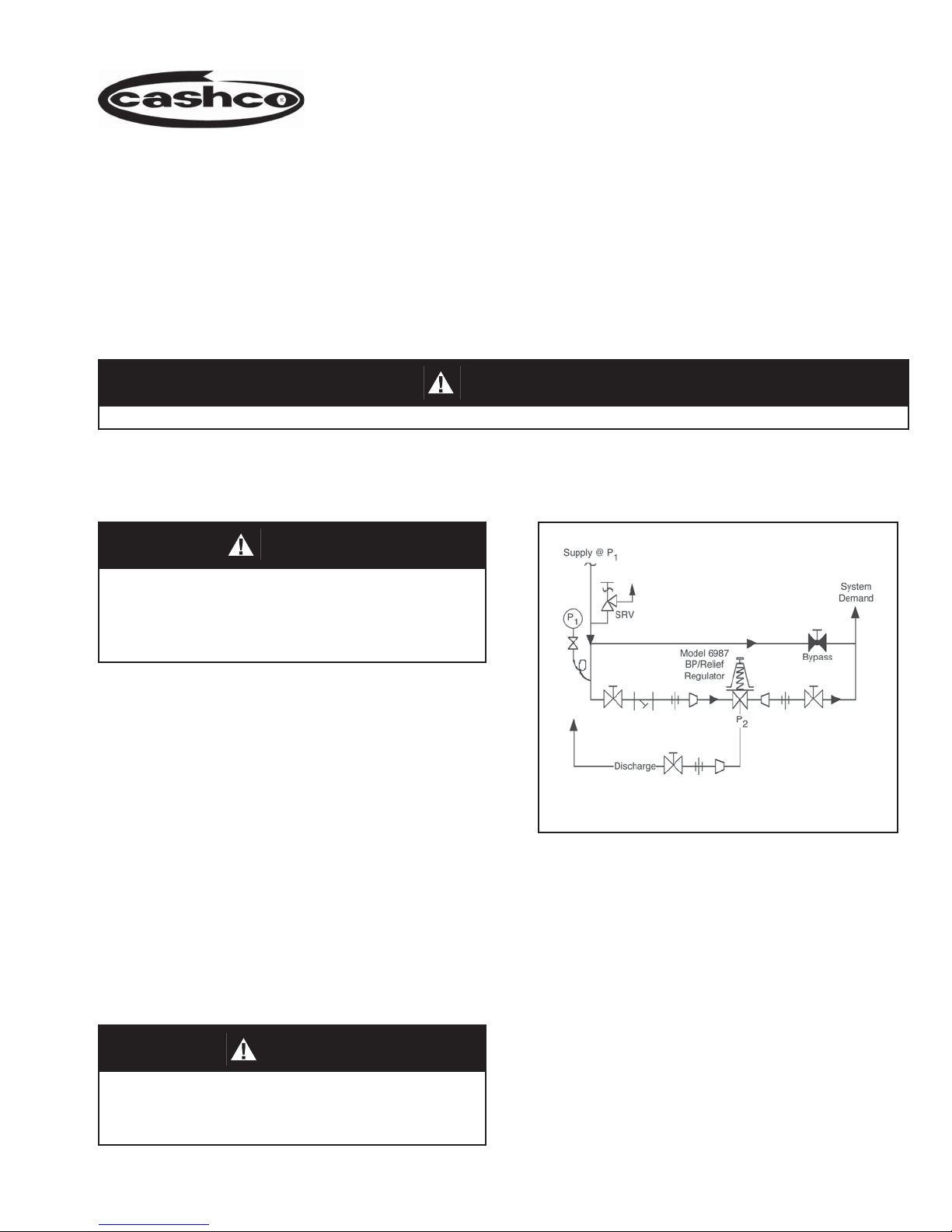
10. Basic Regulator- (See Figure 1): Regulator
may be rotated around the pipe axis 360°.
Recommended positions are with spring chamber
vertical upwards, or horizontal. Orient such that
the spring chamber vent hole does not collect
rainwater or debris.
11. Regulatorsarenottobedirectburiedunderground.
12. For insulated piping systems, recommendation is
to not insulate regulator.
SECTION III
III. PRINCIPLE OF OPERATION
1. Movement occurs as pressure variations register
on the diaphragm. The registering pressure is
the inlet, P1or upstream pressure. The range
spring opposes diaphragm movement. As
inlet pressure drops, the range spring pushes
IV. STARTUP 7. Observing the inlet (upstream) pressure gauge,
rotate the adjusting screw clockwise (CW) slowly
until the inlet pressure begins to rise. Rotate CW
until the desired setpoint is reached.
8. Continue to slowly open the inlet (upstream) block
valve. If the inlet (upstream) pressure exceeds
the desired setpoint pressure, rotate the adjusting
screw CCW until the pressure decreases.
9. When flow is established steady enough that both
the outlet and inlet block valves are fully open,
begin to slowly close the bypass valve if installed.
10. Develop system flow to a level near its expected
normal rate, and reset the regulator setpoint by
turning the adjusting screw CW to increase inlet
pressure, or CCW to reduce inlet pressure.
11. Reduce system flow to a minimum level and
observe setpoint. Inlet pressure will rise from the
setpoint of Step 9. (Ensure that this rise does not
exceed the stated upper limit of the range spring
by greater than 50%, i.e. 50 - 100 psig (3.4 - 6.9
Barg) range spring, at maximum flow the inlet
pressure should not exceed 1.5 x 100 psig (6.9
Barg), or 150 psig (10.3 Barg). If it does, consult
factory.)
12. Increase flow to maximum level if possible. Inlet
(upstream or P1) pressure should fall off. Readjust
setpoint as necessary at the normal flow rate.
1. Start with the block valves closed. A bypass valve
may be used to maintain inlet pressure in the
upstream system without changing the following
steps.
2. Relax the range spring by turning the adjusting
screw counterclockwise (CCW) a minimum of
three (3) full revolutions. This reduces the inlet
(upstream) pressure setpoint.
3. If it is a “hot” piping system, and equipped with
a bypass valve, slowly open the bypass valve
to pre-heat the system piping and to allow slow
expansion of the piping. Closely monitor inlet
(upstream) pressure, via gauge, to assure not
over-pressurizing. NOTE: If no bypass valve is
installed, extra caution should be used in starting
up a cold system; i.e. do everything slowly.
4. Crack open the inlet (upstream) block valve.
5. Slowly open the outlet (downstream) block
valve observing the inlet (upstream) pressure
gauge. Determine if the regulator is flowing. If
not, slowly rotate the regulator adjusting screw
counterclockwise (CCW) until flow begins.
6. Continue to slowly open the outlet (downstream)
block valve until fully open.
the diaphragm down, closing the port; as inlet
pressure increases, the diaphragm pushes up
and the port opens.
2. A complete diaphragm failure may cause the
valve to fail closed.
WARNING
The maximum inlet pressure is equal to 1.5 times the larger
number of the stated range spring on the nameplate, and is
the recommended “upper operative limit” for the sensing
diaphragm. Higher pressures could damage the diaphragm.
(Field hydrostatic tests frequently destroy diaphragms.
DO NOT HYDROSTATIC TEST THROUGH AN INSTALLED
UNIT; ISOLATE FROM TEST.)