IOM-PGR-1
2
1. When a loading pressure – PLoad – is applied to
the top side of a diaphragm, the outlet controlled
pressure – P2– will balance at approximately
.90 – .98 of the loading pressure - PL.
2. Movement occurs as pressure variations register
on the diaphragm. The registering pressure is the
outlet, P2, or downstream pressure. The loading
pressure fluid opposes diaphragm movement.
As outlet pressure drops, the loading pressure
pushes the diaphragm down, opening the port; as
outlet pressure increases, the diaphragm pushes
up and the port opening closes.
3. A diaphragm failure will tend to cause the regulator
to fall below setpoint. A loss of loading pressure
while inlet pressure is imposed will cause the
regulator to fail close.
V. STARTUP
1 Start with the block valves closed.
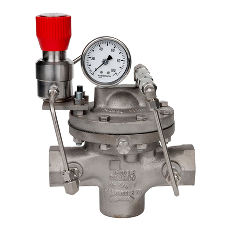
2. Rotate the adjusting screw (30.17) on the pilot
valve CCW so that main regulator is trying to be
controlled at 0 psig pressure. DO NOT rotate
the adjusting screw on the stabilizer, stabilizer
was preset and calibrated at the factory. NOTE:
If an adjustment to the stabilizer is necessary,
it is recommended that a gauge be installed in
optional port downstream of stabilizer. Once flow
is established, if an adjustment is needed, the
stabilizer should be set at 8 to 10 PSI above the
set point attempting to be controlled.
3. DO NOT rotate knob on metering valve, it was
preset at the factory at 2 to 3 full revolutions from
closed position. DO NOT close metering valve.
4. If it is a “hot” piping system, and equipped with
a bypass valve, slowly open the bypass valve
to preheat the system piping and to allow slow
expansion of the piping. Closely monitor outlet
(downstream) pressure via gauge to ensure not
over-pressurizing. NOTE: If no bypass valve is
installed, extra caution should be used in starting
up a cold system; i.e. do everything slowly.
5. Crack open the outlet (downstream) block valve
to approximately 10% full open.
6. Slowly open the inlet (upstream) block valve to
about 25% open. Rotate the adjusting screw
SECTION V
CAUTION
DO NOT HYDROSTATIC TEST THROUGH AN INSTALLED
UNIT; ISOLATE REGULATOR FROM TEST. The "OUTLET
RATING" as printed on the nameplate is the recommended
“upper operating limit” for the sensing diaphragm. Higher
pressures could cause internal damage. In addition, note
on the nameplate that the Inlet and Outlet pressure and
temperature ratings are at different levels.
CAUTION
Do not walk away and leave a bypassed regulator
unattended!
(30.17) on the pilot valve CW to increase setpoint
pressure upwards until the main valve is flowing.
Observe the outlet pressure gauge to ensure not
over pressurizing.
7. Continue to slowly open the inlet (upstream) block
valve until fully open.
8. Continue to slowly open the outlet (downstream)
block valve, especially when the downstream
piping system isn’t pressurized. If the outlet
(downstream) pressure exceeds the desired pres-
sure, close the inlet block valve and go to Step 2.
Close bypass valve approximately 25%, repeat
procedure.
9. When flow is established steady enough that the
outlet (downstream) block valve is fully open, begin
to slowly close the bypass valve if installed.
10. Develop system flow to a level near its expected
normal rate, and reset the regulator set point by
rotating the adjusting screw (30.17) on the pilot
valve CW to change the setpoint to the desired
outlet pressure level. If downstream pressure is
unstable, rotate knob on metering valve in quarter
turn increments CW or CCW to combat instabil-
ity. NOTE: 1/4 turn increments are used due to
sensitivity, in some cases the changes to the P2
are significant. DO NOT rotate knob more than
6 full revolutions from closed position. Metering
valve is preset at factory 2 to 3 full revolutions from
closed position. DO NOT close metering valve.
11. Reduce system flow to a minimum level and
observe pressure set point. Outlet pressure will
rise from the set point of Step. The maximum rise
in outlet pressure on decreasing flow should not
exceed the 10%. If it does, consult factory.
SECTION IV
IV. PRINCIPLE OF OPERATION
