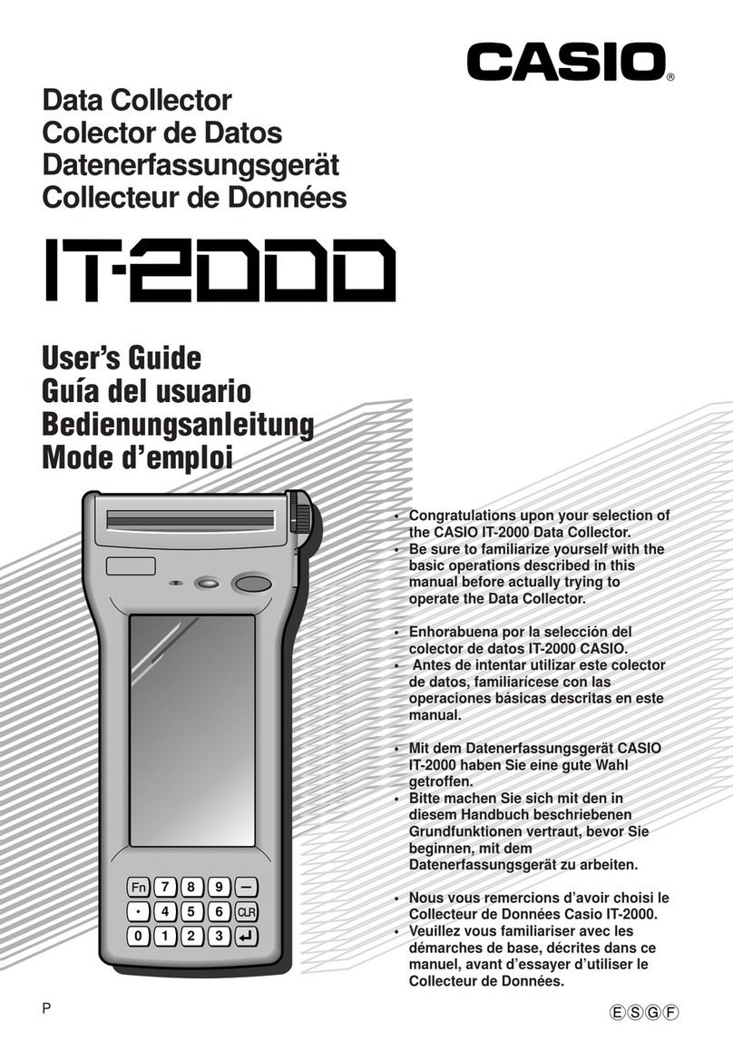
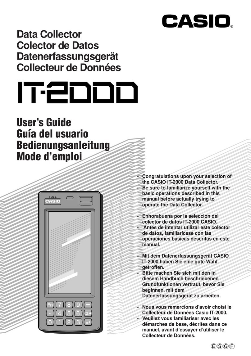
Casio IT-2000W Product manual

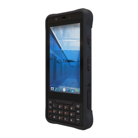
IT-2000W
(Windows version)
Technical Reference
Manual
(Version 1.00 )
April 1998
Casio Computer Co., Ltd.
Copyright ©1998. All rights reserved.

2
Table of Contents
Preface 5
Chapter 1 Overview 6
1.1 Features of System 6
1.1.1 Development Concept 6
1.1.2 Hardware 6
1.1.3 Software 6
1.1.4 Basic Specifications 7
1.1.5 Model Name 8
1.2 System Configuration 9
1.2.1 Hardware Block Diagram 9
1.2.2 Supported Software 10
1.3 Precautions 13
Chapter 2 Basic Software 16
2.1 Overview 16
2.1.1 Software Configuration 16
2.1.2 Memory Map 17
2.1.3 Drive Configuration 18
2.2 Basic System Operation 19
2.2.1 Overview 19
2.2.2 Power ON Process 21
2.2.3 Power OFF Process 25
2.2.4 Battery Voltage Monitoring Process 27
2.2.5 Low Consumption Current Process 31
2.2.6 How to Replace or Recharge Batteries 34
2.3 Supported Devices 36
2.3.1 Display Unit 36
2.3.2 EL Backlight 38
2.3.3 Touch Panel 39
2.3.4 Disk 40
2.3.5 Serial Communication 42
2.3.6 PC Card 44
2.3.7 Clock Timer 46
2.3.8 Buzzer 47
2.3.9 Barcode Reader 48
2.3.10 Infrared Communication (IR) 49
2.3.11 Keys 50
2.3.12 Sensors 51
Chapter 3 System Menu 52
3.1 Overview 52
3.2 Basic Operation 53
3.3 List of Functions 53
3.4 Key Click Sound Setup 54
3.5 Buzzer Volume Setup 55
3.6 Contrast Adjustment 56
3.7 Auto Backlight Setup 57
3.8 Auto Power OFF Setup 58
3.9 Touch Panel Calibration 59

3
3.10 YMODEM Utility 61
3.11 FLINK Command 65
3.12 System Date/Time Setup 68
3.13 Command Prompt 69
3.14 RAM Disk Size Change 70
3.15 Disk Format 72
3.16 System Initialization 74
3.17 Password Entry 75
Chapter4MS-DOS 76
4.1 Overview 76
4.2 How to Write CONFIG.SYS and AUTOEXEC.BAT78
4.3 Card Boot 81
Chapter5MS-Windows84
5.1 Overview 84
5.2 Installation of MS-Windows85
5.2.1 Demonstration Installation 85
5.2.2 Application Installation 86
Chapter6Keyboard Controller 87
6.1 Overview 87
6.2 Keyboard Control 88
6.3 Touch Panel Control Function 90
6.4 Sensor Control 91
6.5 Backlight Control 92
Chapter7Drivers 95
7.1 Overview 95
7.2 System Driver 96
7.2.1 Function 96
7.2.2 Startup Method 96
7.3 Clock Control Driver 97
7.3.1 Function 97
7.3.2 Startup Method 98
7.4 Keypad Driver/Hardware Window Manager 99
7.4.1 Function 99
7.5 PenMouse Driver 100
7.5.1 Overview 100
7.5.2 Startup Method 101
7.6 Virtual Keyboard Driver 102
7.6.1 Function 102
7.6.2 Startup Method 103
7.7 System Library(main program file) 104
7.7.1 Function 104
7.7.2 Operation Method 104
7.8 DisplayDriver 105
7.8.1 Function 105
7.8.2 Startup Method 105
7.9 COM Driver for IrDA 107
7.9.1 Overview 107
7.9.2 Windows 3.1 Communication Functions 109
7.9.3 Setting Up WIN.INI File 135
7.9.4 Installation Method 139
Chapter8Application Development 141
8.1 Overview 141
8.2 Notes on Developing Application 142
8.3 Development Environment 143
8.3.1 Development Environment 143
8.3.2 Application Development Library 143
8.3.3 Simulation Driver 144
8.4 Program Development Procedure 145
8.4.1 Creation of Execution File 146

4
8.4.2 Debugging Through Simulation 147
8.4.3 Operation Check on IT-2000 (Using COM2KEY/XY) 149
8.4.4 Installation of Application Program 150
8.5 Simulation Driver 152
8.5.1 System Driver Simulator (SysCall.DLL) 153
8.6 Library 157
8.6.1 Overview 157
8.6.2 System Library 158
8.6.3 Keypad Library 196
8.6.4 OBR Library 213
Setting Operation Mode/DT-9650BCR 223
Setting Operation Mode/DT-9656BCR 228
8.6.5 YMODEM Library 233
8.6.6 FLINK Library 239
Chapter 9 Utility 257
9.1 Overview 257
9.2 Calculator Utility 258
9.3 Clock Utility 260
9.4 Calendar Utility 262
9.5 Remaining Battery Voltage Display Utility 263
9.6 FLINK Utility 264
9.6.1 Communication Parameter Setup Command 265
9.6.2 File Transmission (/S) 267
9.6.3 File Reception (/R) 269
9.6.4 File Append (/A) 271
9.6.5 File Deletion (/D) 272
9.6.6 File Move/Rename (/N) 273
9.6.7 Idle Start 274
9.6.8 Termination Codes and Messages 275
9.7 XY Utility 277
9.8 Reverse Video Utility 282
9.9 COM2KEY Utility 283
9.10 Windows Installation Utility 284
APPENDIX A TFORMAT.EXE 291
APPENDIX B PC Card Driver 292
APPENDIX C Acquisition of Suspend/Resume Event and
Power Status 295

5
Preface
The IT-2000 Technical Reference Manual (hereinafter referred to as this document) is provided to
assist the user in developing programs to run on the Casio IT-2000 (hereinafter referred to as this
terminal or IT-2000 or HT). Microsoft C/C++ Ver.7.0 or later, and the manuals supplied with it, is
required to develop programs for this terminal.
Read Chapter 1 of this manual in its entirety to understand the features of this terminal.
Important notices to user
The information contained in this document may be modified without prior notice.
Casio Computer Co., Ltd. shall not be liable for any outcome that result from the use of this
document and the terminal.
Copyright notice
The contents of this document are protected by the Copyright Law of Japan.
This document may not be reproduced or transferred in part or in whole, in any form without
permission from Casio Computer Co., Ltd.
Copyright © Casio Computer Co., Ltd. All rights reserved.
About MS-DOS 6.22
The MS-DOS copyright is the proprietary of Microsoft Corporation in the United States and is
protected by the United States Copyright Law and International Treaty provisions.
The MS-DOS software shall not be modified, reverse-engineered, decompiled, or disassembled. Any
form of reproduction is also absolutely prohibited.
About MS-Windows
The MS-Windows copyright is the proprietary of Microsoft Corporation in the United States and is
protected by the United States Copyright Law and International Treaty provisions.
The MS-Windows software shall not be modified, reverse-engineered, decompiled, or disassembled.
Any form of reproduction is also absolutely prohibited.
About trademarks
AT and IBM PC/AT are registered trademarks of International Business Machines
Corporation in the United States.
MS, MS-DOS, Microsoft C/C++, Visual C ++, Visual Basic, and MS-Windows are registered
trademarks of Microsoft Corporation in the United States.

6
1. Overview
1.1 Features of System
1.1.1 Development Concept
The IT-2000 is a data collection terminal for business use. After years of refinement Casio
Computer Co., Ltd. has developed its hand-held type terminals so that they yield high speed and
a high functionality in comparison to general personal computers. This allows improved efficiency
in software development.
It has adopted the IBM PC/AT architecture and incorporated an IBM PC/AT compatible BIOS.
It uses MS-DOS Ver. 6.22 and MS-Windows for its OS. This has drastically improved the software
development environment and compatibility to IBM PC/AT family applications.
The adoption of a power-saving type 32-bit CPU, the Intel 80486GX, allows the terminal to operate
continuously for eight hours (when the backlight is off).
1.1.2 Hardware
Global IBM PC/AT architecture standard is adopted.
Compact design: 85 (W) x 196 (L) x 30 (H) mm, 430 g (approx.)
Uses a 32-bit CPU (Intel 80486 GX) for 25 MHz high-speed operation.
High-resolution (192 x 384 pixels), large-size liquid crystal touch panel.
Supports various interfaces, including RS-232C (8-pin, 14-pin), IR, and PC card.
High environmental adaptability: Operation temperature at between -5 and 50
, water splash
proof capability conforms to the IPxII standard, etc.
Uses a small-size, large capacity lithium-ion battery pack as the main battery.
Incorporates a large capacity flash ROM drive as the user drive.
1.1.3 Software
MS-DOS Ver. 6.22 and MS-Windows as the operating system.
IBM PC/AT-compatible BIOS makes it easy to develop user application programs.
Uses APM 1.1, for advanced low-power consumption capability.

7
PC card slot conforms to PCMCIA Release 2.1 supporting various PC cards.
Implements IrDA 1.1 protocol for high-speed infrared communication.
System menu makes it easy to maintain the IT-2000 and install user application programs.
Provides various development support tools including C-language libraries and communication
utilities for developing business application programs.
1.1.4 Basic Specifications
IT-2000
Architecture
IBM PC/AT architecture
External dimensions and weight
Dimensions : 85 (W) x 196 (L) x 30 (H) mm
Weight : 430 g (approx.)
CPU Intel 80486GX(32-bit)
Memory DRAM : 4 MB
F-ROM : 0/4/8/12/16/24 MB (refer to Chapter 1.1.5)
MASK ROM : 8 MB, Windows file
BIOS ROM : 1 MB (BIOS section: 256 KB, Drive C image: 768 KB)
Display and input
LCD panel : 192 x 384 dots (FSTN semi-transparent LCD), with EL
backlight
Touch panel : Analog, 192 x 384 dots
Interface8-pin : RS-232C
14-pin : RS-232C
IrDA : Standards 1.0/1.1
PC Card : PCMCIA Release 2.1
Power supply
Main battery : Lithium-ion battery pack (x 1)
Sub-battery : Lithium-vanadium battery (x 1), lithium battery (x 1)
Operating hours : 8 hours (if backlight off)
Backup period : 2 weeks (approximately)
Environment conditions : Operation -5 to 50
Temperature : Storage -10 to 55
Water-splash proof : Conforms to IPxII standard
SoftwareBIOS : IBM PC/AT compatible
OS : MS-DOS Version 6.22, MS-Windows
F-ROM : NAND flash file system
Basic functions : Suspend/Resume, Auto Power OFF, Auto Backlight OFF,
Auto Backlight ON/OFF with light intensity detection,
Auto Power ON with timer/ring signal/detection of
mounted I/O Box, Battery voltage monitoring function

8
1.1.5 Model Name
The following IT-2000s of Windows version will be available. For price of each model, please
consult with your local Casio representative.
Model RAM FlashROM Total Remark
IT-2000W20 4 Mbytes 4 Mbytes 8 Mbytes
IT-2000W30 4 Mbytes 8 Mbytes 12 Mbytes
IT-2000W40 4 Mbytes 12 Mbytes 16 Mbytes
IT-2000W50 4 Mbytes 16 Mbytes 20 Mbytes
IT-2000W60 4 Mbytes 24 Mbytes 28 Mbytes

9
1.2 System Configuration
1.2.1 Hardware Block Diagram
CPU
i486GX
1
Power switch
A/D
converter
Buffer
DRAM
FLASH ROM
(DINOR)
BIOS/DOS
MASK ROM
Lithium-ion
battery
Secondary sub-battery
Primary sub-battery
IrDA
Driver/Receiver
RS-232C
driver
PC card slot
IrDA 1.1
IrDA 1.0
16550
PC card
controller
Analog touch
panel
Keyboard
controller
NAND FLASH
NAND
interface
Key
LCDLCTC
VGA
controller
PMU
COM 1
COM 2
Battery voltage monitoring sensor
Temperature sensor
Illumination sensor
8-pin
14-pin
UART/
SIR
BUS
Controller
PMU
ASIC
RTC
RTC
EL Backlight
BL controller

10
1.2.2 Supported Software
The software used with this terminal can be divided into two categories: the system software that
includes the BIOS, OS, and device drivers and the user software such as the development tools.
The system software is stored on the DINOR FLASH ROM (1 MB), and the user software is
supported from the SDK CD-ROM (version 4.0) supplied by Casio at free of charge. The following
paragraphs describe the software.
BIOS
The BIOS program is stored in the DINOR FLASH ROM. 256 KB of DINOR FLASH ROM is
allocated specifically as the BIOS storage area.
The BIOS of this terminal consists of the standard PC/AT BIOS section, PEN BIOS for supporting
the touch panel, extension BIOS for supporting devices inherent to this terminal, and APM BIOS for
attain the low-power consumption capability.
MS-DOS Main Part
The main part of the MS-DOS Ver. 6.22 is stored in drive (C:).
In drive (C:) 768 KB of memory area in the DINOR FLASH ROM (1 MB) is allocated. Because of
the capacity limitation, only the essential MS-DOS files are stored in drive (C:). Therefore, if using
an MS-DOS file that is not included in the main part, copy it from the Backup CD-ROM (title on
CD-ROM: MS-DOS version 6.22 Software) to the F-ROM drive (D:) or RAM disk (A:).
For information about each MS-DOS file refer to an MS-DOS manual, commonly available at book
stores.
Device Drivers and System Files
These files must be loaded via CONFIG.SYS or AUTOEXEC.BAT at boot-up. These files are all
stored in drive (C:).
File name Storage location Description
SYSDRV.SYS Basic drive (C:) System driver
TIME.SYS Basic drive (C:) Clock control driver
CS.EXE, etc. Basic drive (C:) PC card driver
CASIOAPM.COM Basic drive (C: ) Touch-panel enabler
ENDATA.COM Basic drive (C:) ATA card-related data
CKRAMDSK.EXE
CKRAMDSK.DAT Basic drive (C:) RAM disk checker
CALIB.EXE Basic drive (C:) Calibration
SYSMENU.EXE Basic drive (C:) System Menu
HWWMAN.EXE Basic drive (C:) Hardware window manager
KEYPAD.EXE
KEYPAD.DAT Basic drive (C:) Keypad
11
TFORMAT.EXE Basic drive (C:) F-ROM drive formatter
Windows Driver
These drivers are necessary for the Windows to run on IT-2000. Download to F-ROM drive (D: ).
File name Storage location Description
VGA_C.DRV
VGA_NC.DRV MASK ROM drive (E: ) Display drivers
PENMOUSE.DRV SDK Mouse driver
VKD.386 SDK Virtual key driver
IRDA.DLL
IRCOMM.DRV SDK IR communication drivers
Utilities
For information about the utilities refer to Chapter 9 "Utility".
File name Storage location Description
WCAL.EXE SDK Calendar utility
WCALC.EXE SDK Calculator utility
WCLOCK.EXE SDK Clock utility
WCHKBATT.EXE SDK Power status indication utility
XY.EXE XY utility (DOS program)
FLINK.EXE Basic drive (C:) FLINK utility (DOS program)
LCDREV.EXE SDK Reverse video utility
(DOS program)

12
Development Tool Libraries
All the libraries of Windows are provided either as Dynamic Link Library (DLL) or as Visual
BASIC Custom Control (VBX). To use these libraries, download first to a directory in F-ROM
drive (D: ). The files, *.LIB and *.H, are needed when you develop an application program.
File name Storage location Description
LIBSYSW.LIB
SYSCALL.DLL
SYSCALLP.DLL
SYSLIB.H
SDK System library
PADCTRL.VBX
PADCTRL.H SDK Keypad library
LIBOBR.LIB
OBRLIB.H
OBRLIB.DLL
SDK OBR library
LIBYMOD.LIB
YMODEM.DLL
YMODEM.H
SDK YMODEM utility library
FLINK.LIB
FLINK.DLL
FLINK.H
SDK FLINK utility library
COM2KEY.EXE Basic driver (C: ) COM
> KEY for DEBUG
(DOS program)
PMON.COM
PMOFF.COM Basic drive (C:) Switching DOZE mode ON/OFF
(DOS program)

13
1.3 Precautions
If reading the internal clock with INT21h the significant data should include and be limited to
the seconds digits. On this terminal the time is read directly from the RTC so that the correct
time can be attained at any moment, even during extended continuous use. As a result the 1/100
of a second digit is ignored. (refer to Chapter 7.3 “Clock Control Driver”.)
To count time, the counter of DOS or the function provided for reading time must be used.
Time tick count of Windows will be behind 1 second in every 2 minutes.
If it is necessary to reboot the system from an application, use the dedicated system library.
However, the reboot operation that uses INT19h of the BIOS I/F does not work.
Many commercial PC programs use a VGA screen (80 (H) x 25 (V)). If these programs are run
on this terminal (24 (H) x 24 (V)) part of the message may not be displayed on the screen.
For example, some of messages displayed by Windows appear partly (left side of the messages
only) on the screen.
Writing to a PC card should always be performed by terminating the write action through the
flash-out process. Otherwise, if system operation is suspended while writing to an SRAM card
or ATA card, the data on the card may be damaged. To activate this flash-out process use the
“_dos_commit()” function of Visual C/C++ or Commit Function (68h) of DOS.
VGA controller is installed in IT-2000. Logically, it can display 16 different colors each in
single color though only 4 colors at a time are distinguishable. In case of development of
application program in single color, by having four colors, such as RGB (255,255,255), RGB
(192,192,192), RGB (128,128,128), RGB (0,0,0), will help you create an easy-to-see
application program.
Note:
If you wish to select a dither color, first display it on the screen to make sure. Due to technical
reasons the display of the B/W LCD may change to reverse video if an application program
developed by the user on a PC is executed without modification on this terminal. To restore the
normal display use the Reverse Video Utility (refer to Chapter 9.8 “Reverse Video Utility”).
Key input operation is disabled for about one second after the Power has been turned off/on.
This is not a malfunction. This occurs because the monitoring timer starts operating the moment
the Power switch is turned on and does not allow any key input for about one second until this
timer expires. Thus, key input is not possible.

14
If an LB1 event (low main battery voltage) occurs, the alarm buzzer starts sounding and system
operation is suspended about 10 minutes later. If the alarm buzzer starts sounding, terminate the
current operation as soon as possible and recharge the main battery.
This system will not execute an alarm indication to be displayed on the LCD screen for an LB2
event (low sub-battery voltage) or LB3 event (low SRAM card battery voltage). Therefore, the
application program side must acquire these alarm status via the system library and display an
appropriate alarm message on the screen.
If the volume of the buzzer is set to zero by the System Menu or system library, the LB1 (low
main battery voltage) alarm will not be heard. Also, other sounds issued by the system will be
inaudible.
If the system is booted from a PC card and if a large-size program that resides on the card is
called from AUTOEXEC.BAT, an error may result. To avoid this problem refer to Chapter 4.2
“How to Write CONFIG.SYS and AUTOEXEC.BAT".
The time limits that can be set for the Auto Power OFF (APO) function are 0 minute, 1 minute
and 30 seconds, 2 minutes and 30 seconds, up to a maximum of 15 minutes and 30 seconds.
This timer has an error of +/-23 seconds.
Do not open the battery compartment lid while the power is on. If it is opened accidentally, an
emergency alarm sounds. In case such the event occurs, close the lid at once.
When you change the main battery, be sure to switch off the power before opening the lid.
An SRAM card once formatted with the DT-9000 cannot be used or formatted with IT-2000.
If the battery pack is installed for the first time after purchase, or if it is installed after the
IT-2000 unit has not been used for a long period of time, install the battery and wait for
approximately eight seconds before turning the power on. This must be done because it takes
approximately eight seconds until sufficient power can be raised for the emergency process.
And, during this interval the power cannot be turned on even if the Power switch is turned on.
If the power is turned on for the first time after purchase and there is no installed application,
the System Menu will always appear. To start up the application, the application must be
installed first on the IT-2000. (refer to Chapter 8.4.4 “Installation of Application Program” )

15
The backlight is turned off by means of the ABO (Auto Backlight OFF) function. However, it
is turned off 1.3 seconds after the setup time. This is because the system has 1.3 seconds of
monitoring time before the internal timer is started.
During the process of loading Windows after boot-up, do not press the Power switch.
Do not press the Power switch because a processing request is issued before the process handler
is installed, resulting that the processing following the request can no longer be achieved.
This terminal cannot avoid encountering the bugs inherent to Windows. If, for example, the File
Manager is used, dates (such as a date of file creation, etc.) on and after the year of 2000 will
not be displayed correctly. This is caused by a bug within Windows. However, note that the
internal clock will operate properly after the year 2000.
The touch panel calibration program is not supported as part of Windows. Therefore, if
calibrating the touch panel with Windows, terminate Windows and execute the calibration
program from the DOS prompt screen, then return to Windows.
The input process from the touch panel should be designed so that every designation can be
accepted with a single click. On this terminal a double-click can be ignored.
For this system, the two display drivers of VGA_C.DRV and VGA_NC.DRV are provided.
The former will display the mouse cursor and the latter will not display the cursor nor the sand-
glass cursor.
While a file in SRAM card is being opened under Windows, the operation of the access to the
card is aborted if suspend is executed. This will cause INT24 error when the access to the
SRAM card for writing or closing is continued after the resume. When you use an SRAM card
under Windows, please be sure to perform the operation steps in sequence of “open
write
close”.
Do not input “^P” from the DOS prompt. If it is input, “^P” requests DOS to redirect console
output to printer. However, because the IT-2000 does not have a built-in printer, it will enter
into wait mode.
For information about the system library, refer to Chapter 8.6.2, "System Library".
For information about the low voltage alarm notification function refer to Chapter 2.2.4 "Battery
Voltage Monitoring Process"
.

16
2. Basic Software
2.1 Overview
2.1.1 Software Configuration
The following diagram shows the software configuration of the IT-2000W.
Fig.2.1
SysCall.DLL
LibSYSW.LIB
Application Program
LibOBRW.LIB
PADCTRL.VBX
PenMouse.drv
OBRLIB.DLL
Handy Terminal Original Hardware & ROM BIOS
LibYMOD.LIB
YMODEM.DL FLINK.DLL
Mouse Event
LibSYSW.LIB
MS-Windows
AT Architecture
&
ROM BIOS
IrDA Driver
VKD.386
VGA_NC.drv
Display Req.
FLINK.LIB

17
2.1.2 Memory Map
The memory map of the IT-2000 is as follows.
Fig.2.2
Extended Memory
ROM BIOS
NAND DISK BIOS/VGA BIOS
Memory Mapped Disk I/F
100000h
0F0000h
0E0000h
0DC000h
0D8000h
0C8000h
0C0000h
000000h
0A0000h
PC Card I/F
EMS Windows 16 KB x 4
Reserved
Video Buffer
128 KB
System RAM
640 KB

18
2.1.3 Drive Configuration
The drive configuration differs for each model as described in the following table:
RAM disk
Drive A:
[Read and Write] This drive is prepared for use after the RAM disk size is specified from
the System Menu. The contents of this RAM disk will not be erased
through a boot process or by pressing the RESET switch.
Basic drive (DINOR FLASH ROM)Drive C:
[Read Only] This drive starts up MS-DOS. The main body of MS-DOS and
maintenance programs such as the System Menu, etc., are stored in this
drive.
F-ROM driveDrive D:
[Read and Write] Application programs are stored on this drive. The drive size (storage
capacity) differs depending on the model.
Drive for Windows filesDrive E:
[Read Only] A ROM that stores Windows files is assigned to the drive E.
This is a reserved drive on IT-2000D models. In this case note that if this
drive is accessed , an INT24h error will occur.
Drive for booting up from cardDrive F:
[Read Only] This read-only drive functions only while a card is being booted.
For information about the mechanism of booting a card refer to
Chapter 4.3 “Card Boot”.
PC card driveDrive G:
[Read and Write] This drive is required if the application program accesses the PC card.
This drive is prepared for use by loading the PC card driver via
CONFIG.SYS.
Note:
The drive letter of each drive is reserved. Therefore, these drive letters are not changed even if the
RAM disk is not used.

19
2.2 Basic System Operation
2.2.1 Overview
Basic operation of this system on the terminal consists of the suspend/resume process and boot
process operated by means of the Power switch and RESET switch, as shown in the following
diagram.
Fig. 2.3
During normal operation the system status will move between the ON state and the OFF state,
shown in the above diagram, by pressing the power key.
The SUSPEND state is a state from which the previous state can be returned to at any time. The
process of returning from the SUSPEND state to the ON state is called the resume process.
The RESET switch is used to either re-start the system or to initiate the System Menu, which is the
maintenance program. Press this RESET switch to start hardware initialization followed by initiation
of the System Menu. This process is called the System Menu boot process.
If an OFF event occurs while the System Menu is operating, the system shifts to the OFF state.
If the ON key is pressed in the OFF state, the boot process is executed again and an appropriate
application program will be loaded. This process is called the application boot process.
ON STATE
SUSPEND
STATE
OFF STATE
System Menu
OFF EVENT
OFF Process
RESET SWITCH
System Menu BOOT
RESET SWITCH
System Menu BOOT
ON EVENT
ON Process
ON KEY
Application BOOT
OFF EVENT
OFF Process
INITIAL STATE
ON KEY
System Menu BOOT

20
The following table summarizes the power-on processes provided for this terminal.
System Menu boot
process Always executes CONFIG.SYS and AUTOEXEC.BAT located
in drive (C:) for starting up the MS-DOS.
Application boot process Searches for CONFIG.SYS and AUTOEXEC.BAT prepared
by the user and starts up MS-DOS from the drive where they are
located.
Resume process Restores the memory conditions that existed before the power
was turned off and continues operating according to the
conditions.
Table of contents
Other Casio PDA manuals

Casio
Casio PV-250X Technical document

Casio
Casio PV-750 Plus User manual

Casio
Casio PV-750 Plus Instruction and safety manual

Casio
Casio PV-250X User manual

Casio
Casio Cassiopeia IT-700 User manual

Casio
Casio PV-S250 User manual

Casio
Casio PV-250X User manual

Casio
Casio CSF-4450 Troubleshooting guide

Casio
Casio PV-100 User manual

Casio
Casio Cassiopeia E-100 User manual

Casio
Casio PV-750 Plus Use and care manual

Casio
Casio PV-750 Plus User manual

Casio
Casio PV-250X User manual

Casio
Casio PV-100 User manual

Casio
Casio PV-250X User manual

Casio
Casio PV-750 Plus Guide

Casio
Casio PV-750 Plus User manual

Casio
Casio PA-2500 User manual

Casio
Casio Cassiopeia IT-2000 User manual

Casio
Casio CASSIOPEIA E-11 User manual