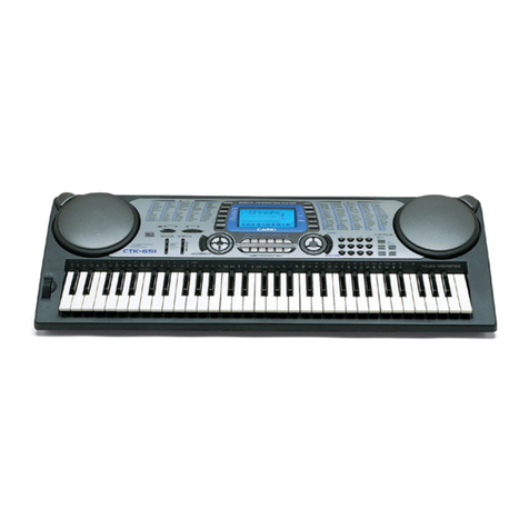
Casio CTK-5000 User manual

CONTENTS
SPECIFICATIONS ------------------------------------------------------------------------------------------ 1
BLOCK AND WIRING DIAGRAM --------------------------------------------------------------------- 3
PCB LAYOUT ----------------------------------------------------------------------------------------------- 4
CIRCUIT DESCRIPTION --------------------------------------------------------------------------------- 5
PRINTED CIRCUIT BOARDS -------------------------------------------------------------------------- 7
DISASSEMBLY --------------------------------------------------------------------------------------------11
DIAGNOSTIC PROGRAM ------------------------------------------------------------------------------22
EXPLODED VIEW ----------------------------------------------------------------------------------------26
PARTS LIST ------------------------------------------------------------------------------------------------27
SCHEMATIC DIAGRAMS -------------------------------------------------------------------------------30

– 1 –
SPECIFICATIONS
Keyboard
Touch Response
Maximum Polyphony
Tones
Built-in Tones
Sampling Tones
Functions
Reverb
Chorus
Metronome
Beats per Measure
Tempo Range
Song Bank
Built-in Songs
User Songs
Step Up Lesson
Lessons
Lesson Part
Functions
Music Challenge
Auto Accompaniment
Built-in Rhythms
User Rhythms
Registration
Recorder
Keyboard Play
Playing Along with a
Built-in Songs
Memory Capacity
Other Functions
Transpose
Octave Shift
Tuning
Scale Tuning
Music Preset
One Touch Preset
Auto Harmonize
Arpeggiator
MIDI
Musical Information Function
61 standard-size keys
2 types, Off
48 notes (24 for certain tones)
670
Up to 8 (Melody Sampling: 5, Drum Sampling: 3)*
Up to 10 seconds
Layer, Split
1 to 10, Off
1 to 5, Off
0, 2 to 6
30 to 255
152
Up to 10*
4 (Listen, Watch, Remember, Auto)
L, R, LR
Repeat, Voice Fingering Guide, Note Guide, Performance Evaluation
20 notes
200
Up to 10 (Accompaniment Edit)*
32 (4 setups × 8 banks)
Real-time recording, playback
5 songs, 6 tracks
1 song (L, R, LR)
Approximately 12,000 notes (total for 6 songs)
±1 octaves (12 semitones)
Upper/Lower ±2 octaves
A4 = approx. 440 Hz ±100 cents
Scale Fine Tune, Quarter Tone, Preset Scales
305
200
12 types
90 types
16 multi-timbre received, GM Level 1 standard
Tone, Rhythm, Song Bank, numbers and names; staff notation, fingering, pedal
operation, tempo, measure and beat number, chord name, etc.

– 2 –
Pitch Bend Wheel
Pitch Bend Range
SD Memory Cards
Supported SD Memory Cards
Functions
Inputs/Outputs
USB port
Sustain/Assignable jack
Phones jack
Line Out R, L/MONO jacks
Audio In jack
Power Jack
Power Supply
Batteries
Battery Life
AC Adaptor
Auto Power Off
Speakers
Power Consumption
Dimensions
Weight
0 to 12 semitones
2GB or less
SMF playback, file storage, file recall, file delete, card format
TYPE B
Standard jack (sustain, sostenuto, soft, rhythm start/stop)
Stereo standard jack
Standard jack × 2
Output Impedance: 2.3kΩ, Output Voltage: 1.5V (RMS) MAX
Stereo mini jack
Input Impedance: 9kΩ, Input Sensitivity: 200mV
12V DC
2-way
6 D-size zinc-carbon batteries or alkaline batteries
Approximately 4 hours continuous operation on alkaline batteries
AD-12
Approximately 6 minutes after last key operation (Operates during battery use only)
12cm × 2 + 3cm × 2 (Output: 6.0W + 6.0W)
12V 18W
95.0 × 37.6 × 13.0 cm (37 7/16× 14 13/16× 5 /8 inch)
Approximately 5.4kg (11.9 lbs) (without batteries)
• Design and specifications are subject to change without notice.
* This data is stored in a shared memory area with a total capacity of approximately 320Kbytes
(1Kbyte = 1,024bytes).

– 3 –
BLOCK AND WIRING DIAGRAM
KC5~KC7,
FI4~FI7,
SI4~SI7
KC0~KC4,FI0~FI3,SI0~SI3 MD0 ~ MD15
MD0 ~ MD15
MA1~ MA18
MA1~MA23
VA5
VCP
VD5
VA3
VDP3
VD3
VD3
Power Supply Circuit
Q6~Q12,D4,5,7,
FU3
VA9 VCVD5 VCP VA5
IC3
IC6
IC2
LVD5
VD3
CN2 (13pin)
CN801 (13pin) CN802 (10pin) CN803 (10pin) CN804 (11pin)
CN7 (4pin)
CN6 (8pin)
CN751 (8pin)
CN3 (11pin)
CN3 (11pin)
CN1 (15pin)
CN21 (15pin)
CN12 (5pin)
CN5 (5pin)
CN4 9pin)
CN3 (15pin) *Not used: 12pin-15pin
CN19 CN20 CN22 CN18
CN14 CN15
CN5 CN6
CN7
CN10 CN11 CN9 CN8
CN12
CN13
CN16
CN17
CN1
CN2
CN4
CN5
CN19 (5pin)CN18 (9pin)
SD CARD PCB
(M805-SDA1)
MAIN PCB (M804-MDA1)
SUB PCB (M805-PSA1)
CONSOLE PCB
(M805-CNB2)
CONSOLE PCB
(M805-CNA2)
CONSOLE PCB
(M805-CNA3)
CONSOLE PCB
(M805-CNA1)
KEYBOARD PCB
(M802-KYA1)
KEYBOARD PCB
(M802-KYA2)
SRAM(4Mbit)
IC9
P2ROM(128Mbit)
IC1
Keyboard Keyboard
MPU
IC7
Filter
IC5
POWER
SUPPLY
CIRCUIT
Filter
IC104
Filter
IC101
CONSOLE PCB
(M805-CNB1)
BUTTON
CONTROLLER
IC2
LCD
CONTROLLER
IC1
Power Amplifier
IC1
Filter
IC105

– 4 –
PCB LAYOUT
PCB Components
MAIN PCB M804-MDA1 MPU, SRAM(4Mbit), P2ROM(128Mbit), Key controller,
SD card, USB, Power supply circuit
SUB PCB M805-PSA1 Power supply circuit, Power amplifer, Phone terminal, Line out,
Audio IN, Pedal, DC IN jack
Console PCBs M805-CNA1 LCD, LCD contorller, Button, Button contorller
M805-CNA2 Speaker
M805-CNA3 Speaker
M805-CNB1 Power Switch, Button
M805-CNB2 Main volume
SD CARD PCB M805-SDA1 SD CARD
Keyboard PCBs M802-KYA1 Keyboard
M802-KYA2
M805-SDA1 PCB
M805-CNA1 PCBM805-PSA1 PCB
M805-CNB1 PCB
M805-CNB2 PCB
M804-MDA1 PCB
M802-KYA2 PCBM802-KYA1 PCB
M805-CNA2 PCB
M805-CNA3 PCB

– 5 –
Note: Each key has two contacts, the first conatct 1 and second contact 2.
Key
Second contact First contact
FI
KC
SI
21
NOMENCLATURE OF KEYS
CIRCUIT DESCRIPTION
KEY MATRIX
KC0 KC1 KC2 KC3 KC4 KC5 KC6 KC7
FI0 C2C2#D2D2#E2F2F2#G2
SI0 C2C2#D2D2#E2F2F2#G2
FI1 G2#A2A2#B2C3C3#D3D3#
SI1 G2#A2A2#B2C3C3#D3D3#
FI2 E3F3F3#G3G3#A3A3#B3
SI2 E3F3F3#G3G3#A3A3#B3
FI3 C4C4#D4D4#E4F4F4#G4
SI3 C4C4#D4D4#E4F4F4#G4
FI4 G4#A4A4#B4C5C5#D5D5#
SI4 G4#A4A4#B4C5C5#D5D5#
FI5 E5F5F5#G5G5#A5A5#B5
SI5 E5F5F5#G5G5#A5A5#B5
FI6 C6C6#D6D6#E6F6F6#G6
SI6 C6C6#D6D6#E6F6F6#G6
FI7 G6#A6A6#B6C7
SI7 G6#A6A6#B6C7
C2 C3 C4 C5 C6 C7

– 6 –
BUTTON MATRIX
SW00 SW01 SW02 SW03 SW04 SW05 SW06
SWI0 SAMPLING
RECORDER
RHYTHM CARD 4 8 9
SWI1 SCALE
EDITOR FUNCTION SONG
BANK TONE 7 5 6
SWI2 RHYTHM
EDITOR
METRONOME
LISTEN WATCH 1 2 +
SWI3 TEMPO
DOWN
START/
STOP
REMEMBER
NEXT 0 - 3
SWI4
CHORDS/
ACCOMP
ON_OFF
TEMPO
UP AUTO
MUSIC
CHALLENGE
SPLIT LAYER
AUTO
HARMONIZE/
APPEGGIATOR
SWI5 VARIATION/
FILL-IN
SYNCHRO/
ENDING
SWI6 NORMAL/
FILL-IN INTRO

– 7 –
PRINTED CIRCUIT BOARDS
Main PCB M804-MDA1
Top View
Bottom View

– 8 –
Sub PCB M805-PSA1
Top View
Top View Bottom View

– 9 –
Console PCB M805-CNA1
Top View
Bottom View
Console PCB M805-CNA2 Console PCB M805-CNA3
Console PCB M805-CNB1
Console PCB
M805-CNB2
Top View
Console PCB M805-SDA1
Bottom View

– 10 –
Keyboard PCB M802-KYA1
Keyboard PCB M802-KYA2
Top View
Bottom View
Top View
Bottom View

– 11 –
DISASSEMBLY
1. Remove the battery cover and then battery.
2. Remove 17 screws and then upper case.
Battery cover
Tips for assembling:
• Fit the the lead wires for the left/right speakers and the bender into the groove of the rib (X15).

– 12 –
3. Remove two lead wires by soldering.
4. Remove two cables by soldering.
5. Make the keyboard unit and the main unit apart.
Lead wire (Red)
Cable (CN2)
Cable (CN3)
Cable (CN3)
Precaution while assembling the main Connector 3.
Number of pins on the PCB and pins on the cable are
different.
Start connecting from the NO.1 pin whose color is
orange.
Lead wire (Black)

– 13 –
6. To remove the main PCB (M804-MDA1).
6-1. Remove three screws on the PCB (M804-MDA1).
6-2. Remove four cables by soldering.
6-3. Remove the PCB (M804-MDA1).
Cable (CN1)
(M805-PAS1)
Cable (CN6)
(M805-SDA1)
Cable (CN5)
(M805-CNA1)
Cable (CN4)
(M805-CNA1)

– 14 –
7. To remove the sub PCB (M805-PSA1).
7-1. Remove six screws on the PCB (M805-PSA1).
7-2. Remove two cables by soldering.
7-3. Remove six lead wires by soldering.
7-4. Remove the PCB (M805-PSA1).
Cable (CN7)
(Pitch bend)
Cable (CN12)
(M805-CNB2)
Lead wire (Yellow)
Lead wire (Gray)
Speaker lead wire
(White)
Speaker lead wire
(Green)
Speaker lead wire (Brown)
Speaker lead wire (Blue)
When removing the
screw, be sure NOT to
misplace the components
fixing the speaker lead
wires.

– 15 –
8. To remove the console PCB (M805-CNB2).
8-1. Remove the volume knob.
8-2. Remove three screws and then the PCB (M805-CNB2).
9. To remove the SD CARD PCB (M805-SDA1).
9-1. Remove three screws and then the PCB (M805-SDA1).
PCB-SPACER-M805
M805-SDA1

– 16 –
10. To remove the console PCBs (M805-CNA1, M805-CNB1).
10-1. Remove 30 screws and then the PCBs (M805-CNA1 and M805-CNB1).
M805-CNA1 M805-CNB1
10-2. Remove the rubber keys.
M805-CNB1 M805-CNA1
Caution while assembling:
8 screws fixating the LCD unit must be screwed
on in adesignated order.When assembling, be
sure to tighten the screws in theorder from 1 - 8
shown in the photo.Failing to do so may cause
display malfunctions.
5 1 3 7
6 4 2 8

– 17 –
11. To remove the console PCBs (M805-CNA2, M805-CNB3).
11-1. Remove eight lead wires by soldering.
11-2. Remove four screws and then the PCBs (M805-CNA2 and M805-CNB3).
Lead wire (Red)
Lead wire (Black)
Lead wire (Red)
M805-CNA2
Lead wire (Black)
Lead wire (Red)
Lead wire (Black)
Lead wire (Red)
M805-CNA3
Lead wire (Black)
M805-CNA3M805-CNA2

– 18 –
12. Remove eight screws and then two speakers.
13. Remove two screws and then the pitch bend.
Table of contents
Other Casio Synthesizer manuals

Casio
Casio CTK-551 User manual

Casio
Casio CT-S300 User manual

Casio
Casio CT-S500 User manual

Casio
Casio CTK-495 User manual

Casio
Casio CTK-650 User manual

Casio
Casio CASIOTONE 310 User manual

Casio
Casio Privia PX-S1000 User manual

Casio
Casio CELVIANO AP-200 User manual

Casio
Casio Casiotone CT-S100 User manual
Casio
Casio MA-150 User manual

Casio
Casio Casiotone CT-S1 User manual

Casio
Casio VZ-10M User manual

Casio
Casio Privia PX-5S User manual

Casio
Casio CTK-530 User manual

Casio
Casio CT-S500 User manual
Casio
Casio ToneBank CT-420 User manual

Casio
Casio VZ-1 User manual

Casio
Casio Casiotone 7000 User manual

Casio
Casio VZ-1 User manual

Casio
Casio CZ-1000 User manual