6
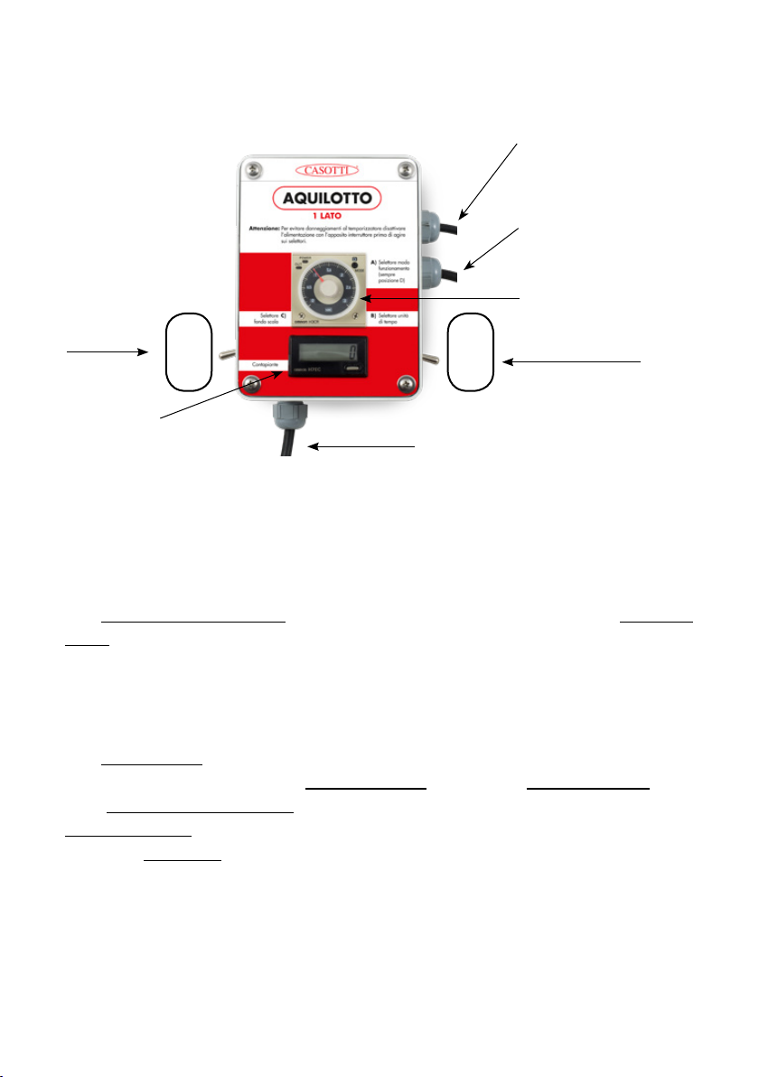
HOW TO ADJUST AQUILOTTO
AQUILOTTO requires two simple adjustments for proper operation.
1)
Position the optical reader at approx. one meter from the nozzles in order
to discharge fluid approx. 10/15cm before the leaves.
The photocell reading system is like an invisible ray which is perfectly
straight in front of the photocell.
This ray can be oriented by moving the case, performing a reading earlier
or later.
If the optical reader is moved away from the nozzles, the reading is
performed earlier and therefore the distance between the fluid discharge
and the leaf increases.
If the optical reader is moved closer to the nozzles, the reading is performed
later and therefore the distance between the fluid discharge and the leaf
decreases.
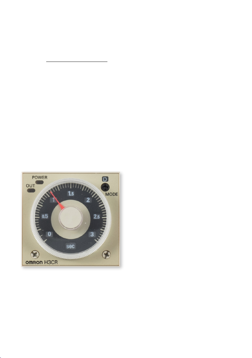
2)
Turn the wheel of the timer located on the control unit in the cab to delay
the solenoid valve closing.
This adjustment allows the fluid to continue flowing out for the desired time,
even if the photocell has ceased to detect leaves.
When AQUILOTTO is properly adjusted, the nozzle jet starts approx.
10/15cm before the leaves and stops approx. 10/15cm after the leaves,
ensuring that all leaves are treated with high accuracy.