Before starting the machine again, by pressing the key RAZ, it is essential that the
origin of the fault is found, (see Fault Indicator Table).
If the "maintenance" indicator lights up it is time to grease the hammer and oil the
horizontal rods.
Having carried out this maintenance the indicator will go out when you press simulta-
neously on the arrow and RAZ keys.
Ensure that the machine is connected to your compressed air and electrical supply.
Open the airline valve fitted at the rear of the machine.
Turn the main switch fitted on the panel to "ON".
VERY IMPORTANT
AFTER JOINING A CORNER IF THERE IS ANY DIFFICULTY IN RELEASING THE MOULDINGS OR FRAME
YOU MUST ENSURE THAT IT IS LIFTED VERTICALLY. IF ANY OTHER MEANS IS USED THERE IS A
POSSIBILITY OF BREAKING THE DISTRIBUTOR HEAD (H).
CHANGING THE CARTRIDGE
Remove the spacer bars in front of the fences Mand N, if these are being used.
Press the arrow key to bring the cross bar to the rear.
Loosen the locking screw of the plunger (F) and pull the plunger upwards.
Remove the cartridge from the rear and snap the sliding finger (FA) under the metal
tongue (FB).
Insert the new cartridge from the rear and slide it forwards until the front of the
cartridge is underneath the distributor head (H).
Lift the lever (HA) to release the sliding finger (FA).
Lower the plunger (F) and retighten the holding screw.
N.B. When the cartridge is empty the indicator is illuminated
If this occurs in the middle of a cycle the mouldings
will remain clamped.
Having inserted the new cartridge, as above,
press the buttons Z to finish off the cycle.
SETTING THE SLIDING TABLE (C) READY FOR JOINING
The cross bar must be in the forward position.
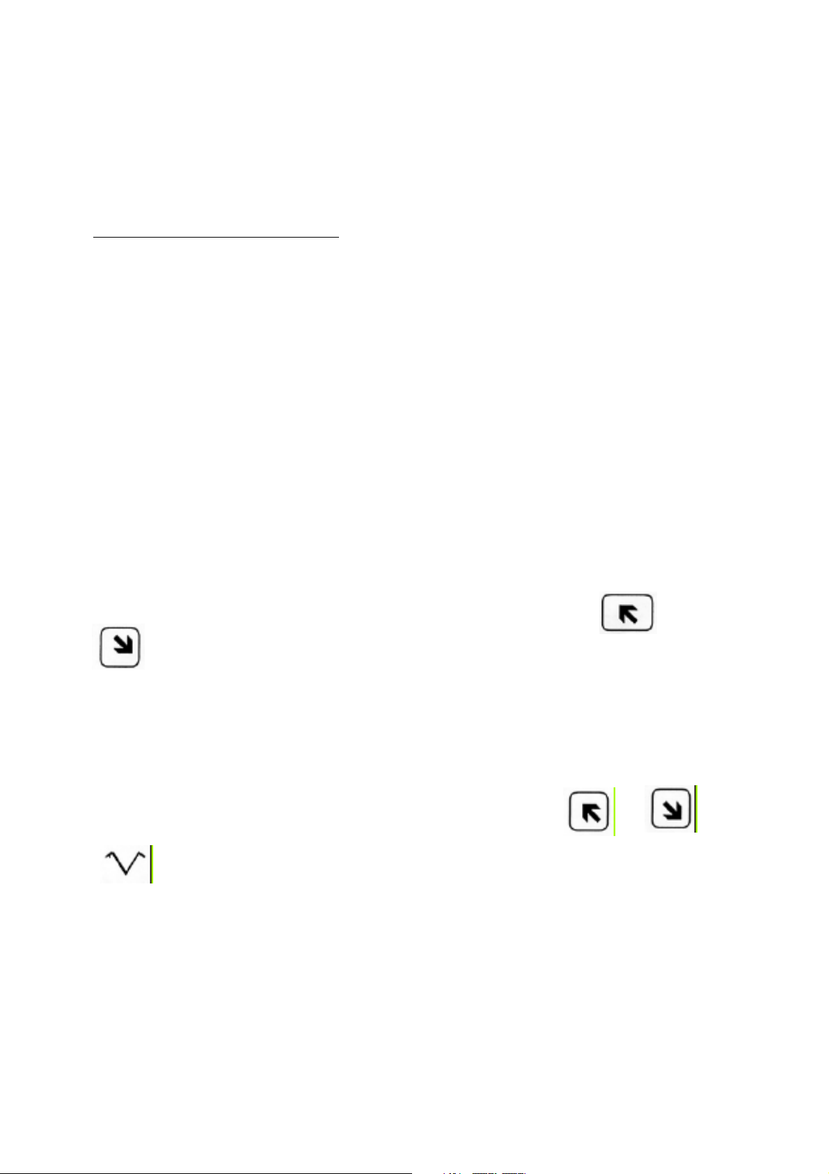
This can be achieved by pressing the appropriate
arrow key
Push down the clamp release handle (J) Fi g 2
Place a piece of the moulding to be joined in
front of the left hand clamp.
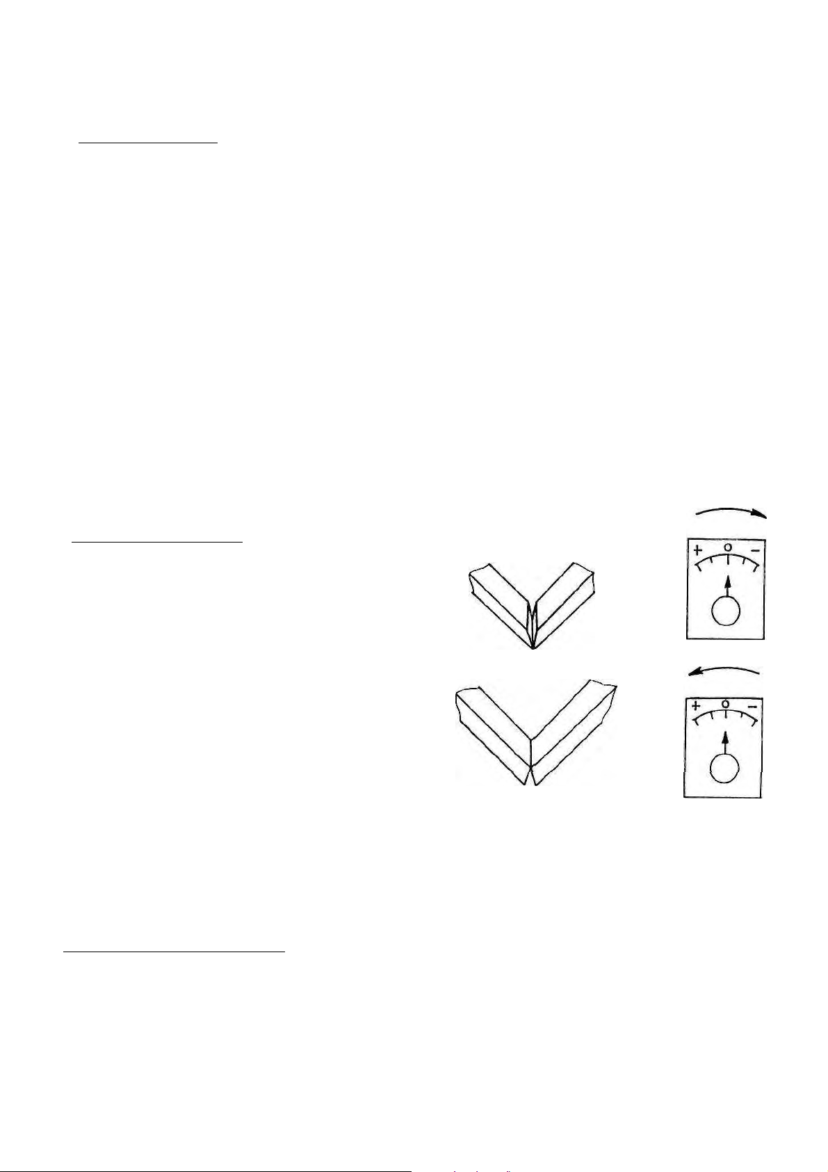
Make sure that the fence tilt knobs (K) are at 0
and that the angle adjustment (L) is correctly
lined up for a 90° angle. Then slide the sliding
table (C) forward until the fence presses the
moulding lightly against the clamp and tighten
locking handle (B).
Lift the clamp release handle ( J) .
When this has been done there should be a clearance of about 1,4mm (1/16") between the
clamp and the moulding.