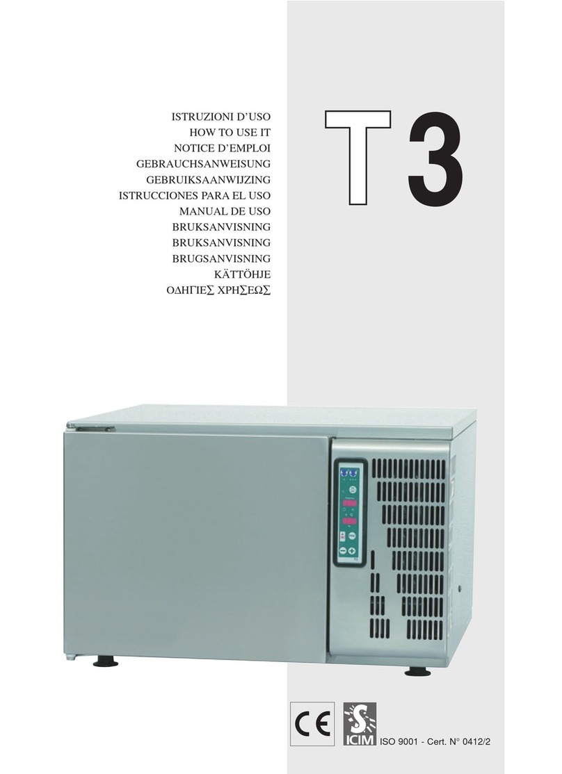
Castel MAC CT10.35 User manual

Users Manual
Multifunction Blas Chillers
- Blast Chiller
- Retarder prover
- Thawing
- Low temperature cooking
- Conservation
- Ice cream hardening cycle
Translation of the Original Instructions
EN
Models : CT10.35 - CT15.65 - CT15-2.70
Low T˚
Models : BT10.35 - BT15.65 - BT15-2.70
Via del lavoro, 9 - 31033 Castelfranco Veneto - Treviso
N. Registro Imprese TV e P.Iva 01866640269 - C.F. 07892570156
Tel. +39 0423.738311 - Fax +39 0423.722811

LEGGERE ATTENTAMENTE IL MANUALE
READ THIS MANUAL CAREFULLY
DAS HANDBUCH AUFMERKSAM LESEN
LEER ATENTAMENTE EL MANUAL
LIRE ATTENTIVEMENT LE MANUEL
NATANČNO PREBERITE PRIROČNIK

Gentile Cliente,
Laringraziamoperaverpreferitounodeinostriprodotti,frutto
di lunga esperienza e di una continua ricerca per un prodotto
superiore in termini di adabilità, prestazioni e sicurezza.
In questo manuale troverà tutte le informazioni ed i con-
sigli per poter utilizzare il suo prodotto nel massimo della
sicurezza ed ecienza.
Il presente manuale costituisce parte integrante del pro-
dotto, e fornisce tutte le indicazioni necessarie per una
corretta installazione, un corretto uso e manutenzione del-
la macchina.
È obbligatorio, da parte dell’utilizzatore, leggere attenta-
mente il manuale e fare sempre riferimento ad esso per
l’utilizzo della macchina. Inoltre deve essere conservato
in luogo noto e accessibile a tutti gli operatori autorizzati
(installatore, utilizzatore, manutentore).
Estimado Cliente,
Le agradecemos haber elegido uno de nuestros pro-
ductos fruto de una larga experiencia y de una conti-
nua investigación para obtener un producto superior
en términos de abilidad, prestaciones y seguridad.
En este manual encontrará todas las informaciones y las
sugerencias para poder utilizar su producto con la máxi-
ma la seguridad y eciencia,
El presente manual es parte integrante del productor y
suministra todas las indicaciones necesarias para una co-
rrecta instalación, un correcto uso y mantenimiento de la
máquina.
Es obligatorio, por parte del usuario, leer atentamente el
manual y hacer siempre referencia al mismo para el uso
de la máquina. Además se debe conservar en un lugar co-
nocido y accesible para todos los operadores autorizados
(instalador, usuario, encargado del mantenimiento).
Dear Customer,
Thank you for choosing one of our products, the result of
lengthy experience and continuous research for a product
that is superior in terms of reliability, performance and safety.
In this manual you will nd all the information and advice
needed to use your product ensuring utmost safety and
eciency.
This manual is an integral part of the product and provides
all the necessary information for correct installation, prop-
er use and maintenance of the machine.
The user must read the manual and refer to it when us-
ing the machine. It must also be kept in a place known
and accessible to all authorised operators (installer, user,
maintenance technician).
Sehr geehrter Kunde,
Wir danken Ihnen für Ihre Wahl eines unserer Produk-
te, welches das Ergebnis einer langen Erfahrung und
stetiger Forschungsarbeit ist. Dank dieser konnte ein
Produkt entwickelt werden, das ein hohes Maß an Ver-
lässlichkeit, Leistungsfähigkeit und Sicherheit bietet.
In diesem Handbuch nden Sie alle Informationen und
Ratschläge, damit Sie das Produkt mit maximaler Sicher-
heit und Ezienz nutzen können.
Das vorliegende Handbuch ist ein wesentlicher Bestand-
teil der Maschine und liefert alle erforderlichen Informati-
onen für die korrekte Installation, den sachgemäßen Ge-
brauch und die Wartung der Maschine.
Der Benutzer ist verpichtet, das Handbuch aufmerksam zu
lesen und sich beim Gebrauch der Maschine an die darin ent-
haltenen Anweisungen zu halten. Außerdem ist das Handbuch
an einem für alle Bediener zugänglichen und bekannten Ort
aufzubewahren (Installateur, Bedienungs - und Wartungsper-
sonal).
Cher Client,
Nous vous remercions d’avoir choisi l’un de nos pro-
duits, qui est le fruit d’une longue expérience et
d’une recherche continue pour un produit supérieur
en termes de abilité, de prestations et de sécurité.
Vous trouverez dans ce manuel toutes les informations et
les conseils pour pouvoir utiliser le produit dans des condi-
tions maximales de sécurité et de performance.
Ce manuel fait partie intégrante du produit et fournit toutes
les indications nécessaires à l’installation, l’utilisation et
l’entretien corrects de la machine.
L’utilisateur a pour obligation de lire attentivement le ma-
nuel et de toujours y faire référence lors de l’utilisation de
la machine. Il doit par ailleurs être conservé dans un en-
droit connu et accessible à tous les opérateurs autorisés
(installateur, utilisateur, agent de maintenance).

In particolare lo sono :
- Allacciamenti elettrici
- Allacciamenti idrici
- Installazione della macchina
- Collaudo della macchina
- Interventi di riparazione su tutti i componenti e organi
della macchina
- Smontaggio della macchina e/o dei suoi componenti
- Interventi di regolazione e taratura
- Manutenzione e pulizia della macchina relativa a parti e
componenti (elettrici, elettronici, meccanici, frigoriferi)
- Ricarica gas refrigerante
LE OPERAZIONI EVIDENZATE CON QUESTO SIMBOLO
SONO STRETTAMENTE RISERVATE AL TECNICO PATEN-
TATO.
1
IIL TESTO EVIDENZIATO CON QUESTO SIMBOLO È DI PARTICO-
LARE IMPORTANZA O SEGNALA POTENZIALE PERICOLO
iNota: chiarisce le operazioni in corso
OPERATIONS HIGHLIGHTED WITH THIS SYMBOL ARE
STRICTLY RESERVED TO CERTIFIED TECHNICIANS.
1
In particular these include:
- Electrical connections
- Hydraulic connections
- Machine installation
- Testing of the machine
- Repairs on all the components and parts of the machine
- Dismantling of the machine and/or of its components
- Operations of adjustment and calibration
- Maintenance and cleaning of the machine for parts and
components (electrical, electronic, mechanical, chilling)
- Recharge refrigerant gas
iNote: it claries operations in progress
THE TEXT HIGHLIGHTED WITH THIS SYMBOL IS OF PARTICU-
LAR IMPORTANCE OR SIGNALS POTENTIAL DANGER
I
DIE MIT DIESEM SYMBOL GEKENNZEICHNETEN
VORGÄNGE SIND STRENGSTENS FACHTECHNIKERN
VORBEHALTEN.
1
iANMERKUNG: Erläutert die im Gang
bendlichen Vorgänge
Insbesondere handelt es sich um:
- Elektrische Anschlüsse
- Wasseranschlüsse
- Installation der Maschine
- Abnahmeprüfung der Maschine
- Reparatureingrie auf allen Komponenten und Teilen der
Maschine
- Demontage der Maschine und/oder ihrer Komponenten
- Eingrie der Einstellung und Eichung
- Wartung und Reinigung der Maschine bezüglich ihrer
Teile und Komponenten (elektrische, elektronische, me-
chanische, des Kühlsystems)
- Kühlmittel auüllen
DER MIT DIESEM SYMBOL GEKENNZEICHNETE TEXT IST
BESONDERS WICHTIG ODER ZEIGT MÖGLICHE GEFAHR AN
I
1LAS OPERACIONES EVIDENCIADAS CON ESTE SÍMBOLO
ESTÁN EXTRICTAMENTE RESERVADAS AL TÉCNICO
HABILITADO.
En particular son :
- Conexiones eléctricas
- Conexiones hídricas
- Instalación de la máquina
- Prueba de la máquina
- Operaciones de reparación en todos los componentes y
órganos de la máquina
- Desmontaje de la máquina y/o de sus componentes
- Operaciones de ajuste y de calibrado
- Mantenimiento y limpieza de la máquina relativa a par-
tes y componentes (eléctricos, electrónicos, mecánicos,
frigorícos).
Recarga gas refrigerante
EL TEXTO EVIDENCIADO CON ESTE SÍMBOLO ES DE
PARTICULAR IMPORTANCIA O SEÑALA POTENCIAL PELIGRO
I
NOTA: aclara las operaciones en curso
i
LES OPERATIONS SIGNALEES PAR CE SYMBOLE SONT
STRICTEMENT RESERVEES AU TECHNICIEN QUALIFIE.
1
Notamment :
- Raccordements électriques
- Raccordements au réseau d'eau
- Installation de la machine
- Essai de la machine
- Interventions de réparation sur tous les composants et
les organes de la machine
- Démontage de la machine et/ou de ses composants
- Interventions de réglage et d'étalonnage
- Entretien et nettoyage de la machine relatifs à des par-
ties et des composants (électriques, électroniques, méca-
niques, frigoriques)
- Recharge de gaz réfrigérant
LE TEXTE SIGNALE PAR CE SYMBOLE EST D'UNE IMPORTANCE
PARTICULIERE OU SIGNALE UN DANGER POTENTIEL
I
NOTE : donne des précisions sur les opérations
en cours
i

5
I
The user must carefully read the manual and
always refer to it when using the machine.
Moreover, it must be stored in a place known
and accessible to all authorised operators
(installer, user, maintenance technician). Be
sure to use only the supplied or specied in-
stallation components.
In the event of sale or transfer of the appli-
ance, this manual must be handed over to
the new user.
Any contractual and non-contractual liability
of the manufacturer is excluded regarding
damage caused by errors in installation or
operation and, moreover, by non-compliance
with current National and Local regulations
and with the instructions provided by the
manufacturer.
The appliance has been designed to oper-
ate inside the cell at a temperature between
-40°C and 85°C. It can also reach maximum
relative humidity values of up to 100%. More-
over, it has been designed exclusively for
use with food. The manufacturer shall not be
held responsible for temperature adjustment,
which, even within the specications, may
damage the food, due to a careless choice of
parameters by the user.
The appliance mainly performs cooling, heat-
ing and humidication functions, within the
ranges described.
• Do not operate the appliance before
technician assistance.
• The machine is designed for professional
use and therefore only qualied persons
may use it.
• Themanufacturerdeclinesanyresponsibility
for any damage caused by improper and
unreasonable use, such as improper use by
unskilled personnel, technical modications
or interventions not specic for the models
or even partial non-compliance of the
instructions hereof.
• The machine is only intended for the
use for which it was designed, namely
for the freezing or storage of foodstus.
Excluded are products that require constant
temperature monitoring and recording, such
as thermo-reactant chemicals, medicines
and blood products.
• The GWP (Global Warming Potential) of
R452A gas is 2141.
• The equivalent CO2 data is indicated on the
serial number plate (see para. 2.1).
• According to the ISO 817 standard, R452A
gas is not a ammable gas.
• In high concentrations it can be asphyxiating.
Contact with liquid can cause burns and
frostbite.
• The gas in the system is pressurised; it may
explode if heated.
• Do not store explosive substances in this
unit, such as aerosol cans with a ammable
propellant.
• ATTENTION: Do not use electrical appliances
inside the appliance compartments for the
storage of frozen foods if they are not of the
type recommended by the manufacturer
• ATTENTION: Keep the ventilation openings
in the casing of the equipment or in the
recessed structure free from obstructions.
• ATTENTION: Do not use mechanical devices
or other means to accelerate the defrosting
process, other than those recommended by
the producer.
• ATTENTION: do not damage the refrigerant
circuit.
• ATTENTION: when positioning the appliance
make sure that the power cord is not trapped
and damaged.
• ATTENTION: Do not place multiple portable
sockets or portable power supplies on the
back of the appliance.
• This appliance was designed to be used for
household and similar applications, such
as:
- the kitchen area intended for commercial
personnel, oces and other working
environments;
- factories and by customers in hotels, motels
and in other residential environments;
- bed and breakfast establishments;
- non-retail catering services and similar
applications.
• Check that the identication plate data and
the electrical line characteristics match(V,
KW, Hz, phase number and available power)
• Do not pull the power cord to disconnect the
machine from the power supply.
• If the power cord is damaged, it must be
replaced by the manufacturer or by its
1 - WARNINGS AND IMPORTANT ADVICE
ENGLISH

66
technical assistance service or in any case
by a person with similar qualication, such
as to prevent any risk.
• The appliance can be used by children of at
least 8 years old and by persons with reduced
physical, sensitive or mental capabilities,
or who do not have proper experience and
knowledge, unless they are supervised
or instructed on the use of the appliance
and provided they understand the related
hazards. The cleaning and maintenance
intended to be performed by the user must
not be performed by unsupervised children.
Children should not play with the appliance.
• Loading and unloading of the appliance from
the means of transport can be performed
with a forklift truck or with a pallet truck
with lengths greater than half of the unit.
The lifting vehicle must be selected based
on the dimensions of the packed machine/
components and with proper capacity.
• When handling the appliance, all necessary
precautions must be taken to avoid
damaging it.
• After removing the packaging, make sure
that the machine/sub-assemblies are intact.
If in doubt, do not use it and contact the
reseller.
• All the components of the packaging must
be disposed of according to the regulations
in force in the country where the appliance
is being used. In any case, nothing must be
disposed of in the environment.
The appliance:
• must be installed in places where it can be
checked by qualied personnel.
• must not be installed outdoors or in dusty
environments.
• must not be placed in areas where there are
jets of water, and it must not be washed with
jets of water.
• must be installed and tested in full
compliance with accident prevention
regulations, traditional regulations and
current regulations.
• must be positioned at least 300 mm away
from the rear wall
• must have a free space of at least 150 mm
on both sides
• there must be a minimum distance of 300
mm between the appliance and the ceiling
• Avoid places exposed to the direct sun rays,
closed spaces with high temperatures and
poor ventilation and avoid installing the
machine close to any source of heat
• The installer should check any re
prevention requirements (contact the local
re brigades for proper indications).
• Place the machine in its nal location making
sure it is perfectly level
• Before carrying out any cleaning or
maintenance operations, disconnect the
machine from the power supply by operating
the main switch and unplugging it. If the
socket is at a distance or in a position that
cannot be controlled by the operator or
the appliance is not equipped with a plug,
a device for electrical padlocking must be
installed to avoid accidental connection of
the appliance.
• ordinary and extraordinary maintenance
operations must only be performed by
qualied installers.
• We decline any liability for damages to
persons, animals or things resulting from
failure to ground the equipment and the
performance of an electrical system which
is not compliant with applicable regulations.
• In case of maintenance requiring the
replacement of parts of the machine, the
use of original spare parts is mandatory.
For information contact the seller or the
technical assistance of the manufacturer.
• The sound pressure level is lower than 70
dB (A).
• Do not touch and operate the machine with
wet or damp hands or feet.
•
• Do not insert screwdrivers, kitchen utensils
or anything between the guards and the
moving parts.
•
• The maximum load permissible per shelf is
20 kg and in total 100 kg.
• It is forbidden to use the equipment in
an environment where ammable gas is
present or in an environment where there is
a risk of explosion.
•
• In case of anomalous operation of the
appliance or with the appearance of alarms
on the display, see chap. 1717 (depending on
the model) for the explanation and resolution
of the problems.
• In the event of alarms that stop the machine,
disconnect the electrical power supply
and the water supply and call a qualied
technician
ENGLISH

7
• Removal of the pallet requires the presence
of at least two persons. Remember that the
heaviest part of the product is at the top.
• For appliances with a water condenser
unit, the water supply temperature must be
between 10°C (50°F) and 30°C (86°F) and the
operating pressure must range between 0.1
MPa (1 bar - 14 psi) and 0.5 MPa (5 bar - 72
psi)
• Check the tightness of the straps, nuts
and bolts, screws and clamps that may
have come loose during transportation to
avoid water leaks or other problems during
machine operation.
• Appliances that are out of order must be
disposed of in compliance with the local
laws and regulations in force.
• The minimum frequency of the various
ordinary and extraordinary maintenance
operations must be as follows: daily cell
cleaning (by user), cleaning of the condenser
shaft and evaporator coil every 30 days (by
qualied technicians)
This appliance and its accessible parts can be-
come very cold or very hot during use. Wait for
the internal surfaces of the appliance return to
room temperature before touching them.
In blast chillers without a power plug, a dif-
ferential switch and a circuit breaker must be
installed upstream.
There must also be a power supply discon-
nector, which disconnects it from the omnip-
olar network, with a contact distance that al-
lows for complete disconnection in category
III overvoltage conditions. For the AS/NZS
market, the requirement is met if performed
as per the AS/NZS 3000 installation standard.
All installed devices must comply with the
regulations in force in the country of instal-
lation.
For installation operations, refer to chapter
3; for operation refer to chapters from 5 to
16; for maintenance and adjustment refer to
chapter 4; for the meaning of the alarms refer
to chapter 17.
Connect only to the drinking water network
and use the new set of mobile ttings (water
inlet/drain pipe) supplied with the appliance.
The old set of ttings should not be reused.
For the characteristics of the models and
their weights, see Table 1.0.
In the case of low temperature baking cycles,
since it is not possible to exclude the spill-
age of hot food during handling, protective
measures must be taken against burns due
to hot food, for temperatures that can reach
100°C.
In addition to this, appropriate footwear must
be worn and precautions must be taken to
prevent accidental falls caused by slippery
oors near the appliance.
• We summarise the parameters that dene
the climatic class, which appears on the
identication plate.
Environmental climate classes (ISO 23953-2)
Climate class Temperature Humidity
1 16°C 80%
2 22°C 65%
3 25°C 60%
4 30°C 55%
5 40°C 40%
6 27°C 70%
ENGLISH

88
REGOLAMENTO (UE) 2015/1095 REGULATION (EU) 2015/1095 VERORDNUNG (EU) 2015/1095 RÈGLEMENT (UE) 2015/1095 PRAVILNIK (EU) 2015/1095REGLAMENTO (UE) 2015/1095
Tab. 1.0
ENGLISH

9
DIMENSIONS
ENGLISH

1010
1 - WARNINGS AND IMPORTANT ADVICE .............................5
2 TECHNICAL DATA ...............................................................11
2.1 - Identication plate.........................................................11
2.2 - Load limits.....................................................................11
2.2.1 Maximum load of the internal structure .......................11
2.2.2 Tray capacity ...............................................................11
2.3 Refrigerant ......................................................................11
3 INSTALLATION.....................................................................12
3.1 Transportation and handling...........................................12
3.2 Unpacking and disposal.................................................12
3.3 Positioning......................................................................12
3.4 Ambient temperature and air exchange ..........................13
3.5 Hydraulic connection for water cooled condensing units13
3.6 Electrical connection ......................................................13
3.7 Remote group refrigerator connection ...........................13
3.8 Condensate drainage connection (if applicable)............13
3.9 Notes for the installer .....................................................13
.............................................................................................13
3.10 Commissioning.............................................................14
3.11 Safety and control systems ..........................................14
3.12 Stop modes..................................................................14
3.13 Signalling/reports of malfunctioning .............................14
3.14 Waste electrical and electronic equipment - WEE (not
valid for xed installations)....................................................14
4 - ORDINARY MAINTENANCE..............................................14
4.1 Operations by the user (that do not require the assistance
of a qualied technician) .......................................................14
4.1.1 Room cleaning ...........................................................14
4.1.2 Outer casing cleaning ................................................14
4.1.3 Defrost water drainage ...............................................14
4.1.4 Ozone sanitation (optional).....................................15
4.2 Operations that must be performed by an authorised installer
..............................................................................................15
4.2.1 Condenser cleaning ...................................................15
4.2.2 Condenser lter cleaning ...........................................15
4.2.3 Evaporator cleaning ...................................................15
4.2.4 Ozonator maintenance ...............................................15
5 ADVICE FOR PROPER OPERATION ..................................16
5.1 Operating instructions .....................................................16
5.2 Pre-cooling......................................................................16
5.3 Loading of the machine..................................................16
6 MACHINE START-UP AND SHUT DOWN .........................17
6.1 General information........................................................17
6.2 Entry and exit from Stand-by..........................................17
7 INITIAL SETTINGS .............................................................17
7.1 Language .......................................................................17
7.2 Unlocking the display ......................................................18
7.3 Date and time setting ......................................................18
7.4 Setting the 24-48-72 H cycle duration............................19
8 CHILLING / FREEZING CYCLES.........................................20
8.1 Summary of Positive chilling cycles ................................20
8.2 Starting the MANUAL Positive Chilling ..........................21
8.3 Summary of Negative chilling cycles...............................22
8.4 Starting the MANUAL Negative Chilling..........................23
8.5 Saving the Positive / Negative chilling cycle ..................24
8.6 Change the preservation cell set point...........................24
8.7 Needle probe removal....................................................24
9 THAWING CYCLE ...............................................................25
9.1 Manual Thawing..............................................................25
9.2 Programmed Thawing.....................................................26
INDEX
10 RETARDER PROVING CYCLES........................................28
10.1 Manual retarder proving cycle.......................................28
10.2 Programme retarder proving cycle................................29
11 LOW TEMPERATURE COOKING CYCLES .....................31
11.1 Timed Manual Cooking Cycle........................................31
11.2 Manual Temperature cooking cycle...............................32
11.3 Programme Cooking Cycle ...........................................33
12 ICE CREAM CYCLE ...........................................................35
12.1 Ice Cream Manual cycle................................................35
13 PRESERVATION CYCLE....................................................36
13.1 Manual preservation cycle ............................................36
14 PROGRAMME WRITING...................................................37
14.1 Access to programme set-up .......................................37
14.2 Creation of a Chilling Programme.................................38
14.3 Creation of a Thawing programme................................39
14.4 Creation of a retarder proving programme....................40
14.5 Creation of an ice cream programme............................41
14.6 Creation of a cooking programme.................................41
14.7 Creation of a preservation programme .........................43
15 STARTING UP STORED PROGRAMMES.........................44
15.1 Access to stored programmes......................................44
15.2 Starting up from stored programmes ...........................44
16 STARTING THE UTILITY FUNCTIONS..............................45
16.1 Access to UTILITY window ...........................................45
16.2 Display LOCK function..................................................45
16.3 List/Export of alarms .....................................................45
16.4 Starting the manual defrosting ......................................46
16.5 Starting the Drying cycle ...............................................46
16.6 Starting the OZONO cycle (optional) ............................46
16.7 Conguration of the main menu...................................47
17 Alarm statuses .................................................................48
17.1 Alarm warnings.............................................................48
17.2 Warnings for SERIOUS alarms...................................48
17.3 Warnings for AVERAGE alarms ...................................48
17.4 Pre-alarm warnings......................................................48
17.5 Machine information/data.............................................48
17.6 Alarm list.......................................................................49
ENGLISH

11
2.1 - Identication plate
The identication plate providing information on the char-
acteristics of the equipment is applied to the rear side of
the machine and/or on the electrical cabinets.
The climate class of the equipment is indicated on the
identication plate
Environmental climate classes (ISO 23953-2)
Climate class Temperature Humidity
1 16°C 80%
2 22°C 65%
3 25°C 60%
4 30°C 55%
5 40°C 40%
6 27°C 70%
Furthermore the following symbols indicate the power ab-
sorbed by:
Blast chilling cycle
Baking cycle
2.2 - Load limits
I
Operators must strictly observe the maximum loads
shown in the tables below
2.2.1 Maximum load of the internal structure
Maximum load (kg)
Model Internal structure Load by shelf
10 T 45 kg 20 kg
15 T 80 kg 20 kg
30 T 85 kg 20 kg
2.2.2 Tray capacity
(68 mm step)
Model
Tray dimensions 10 T 15 T 30 T
600x400 mm 10 15 30
530x325 mm 10 15 30
600x800 mm n/a n/a 15
530x650 mm n/a n/a 15
2.3 Refrigerant
The appliance contains uorinated greenhouse gas
regulated by the Kyoto Protocol, in the quantities indi-
cated in the serial number plate.
The type and quantity of refrigerant gas from the cool-
ing circuit of the equipment is given in the serial num-
ber plate
The GWP (Global Warming Potential) of HFC gas:
R134a= 1430 - R404A= 3922 - R452A= 2141
The equivalent CO2 gas is present in the serial num-
ber plate
I
According to Regulation (EC) 1272/2008, the R-134a,
R-404A and R-452A gases are non-ammable and
non-toxic. They can be asphyxiating in high concen-
trations. Contact with the liquids can cause burns and
frostbite.
The gas in the system is pressurised; it may explode
if heated.
2 TECHNICAL DATA
ENGLISH

1212
3 INSTALLATION
1ALL STAGES OF INSTALLATION MUST
BE CARRIED OUT IN COMPLIANCE WITH THE
NATIONAL STANDARDS IN FORCE ACCORDING
TO THE MANUFACTURER’S INSTRUCTIONS AND
BY PROFESSIONALLY QUALIFIED PERSONNEL
Installation of the appliance and of the refrigerating unit must
only be carried out by technicians of the manufacturer or
by skilled personnel.
If the machine was supplied with a remote condensing unit,
it is the installer’s responsibility to check all the connections
in accordance with the instructions provided for the instal-
lation of systems and machinery.
The installer is advised to use the appropriate personal
protective equipment necessary for processing and in
compliance with the regulations in force
3.1 Transportation and handling
The net and gross weight of this appliance can be found on
the external packaging.
Loading and unloading of the appliance and/or of the sub-
systems from the means of transport can be performed
using a forklift truck or fork pallet truck, the length of which
is more than half that of the unit or using cranes where the
appliance/subsystem is tted with eyebolts. The lifting equip-
ment must be chosen according to the size of the packaged
machine/components and with sucient capacity.
For handling of the appliance/subsystems, every precau-
tion must be taken not to damage them, respecting the
indications on the packaging.
3.2 Unpacking and disposal
Remove all cardboard or the wooden crate from the base
on which the machine is placed. Then lift the machine/sub-
assemblies with a suitable means (forklift truck); remove the
wooden base and position the machine/sub-assemblies in
the place provided.
After removing the packaging, verify the integrity of the
machine/sub-assemblies In case of uncertainty do not use
it and contact the distributor.
Remove the protective PVC lm on the stainless steel pan-
els from all sides both internally and externally.
.
i
Note: all the various compo-
nents of the packaging must
be disposed of according to
the regulations in force in the
country where the appliance is
being used. In any case noth-
ing must be disposed of into the
environment.
.
3.3 Positioning
I
The appliance:
• must be installed in places where it can be checked
by qualied personnel.
• it must not be installed outdoors.
• it must not be installed in dusty environments.
• it must not be placed in locations with the presence
of water jets.
• it must not be washed with water jets.
• It must be installed and tested in full compliance
with safety laws, traditional systems and with the regu-
lations in force.
• it must be positioned at a minimum distance of 300
mm from the rear wall, and lateral of 150 mm.
The installer must verify any requirements for re safety
(refer to the command of the local re department for the
relevant indications).
Level the appliance through adjustment of the feet. For the
setting up of heavier machines, use dedicated hoists (g.
A - Chap. 3.1).
If the appliances are not levelled their functioning and the
ow of condensates could be impaired.
g. A
I
Pay attention to the presence of the condensate drain pan
and its supports
I
Avoid locations exposed to direct sunlight, indoor envi-
ronments at high temperatures and poor air circulation
and avoid installing the machine near any heat sources
ENGLISH

13
3.4 Ambient temperature and air exchange
For air cooled liquid chillers, the ambient operating
temperature must not exceed 32°C. Above this tem-
perature the declared performance is not guaranteed.
The machine can operate safely up to a temperature that is
referred to by the climatic class indicated on the serial plate.
Remote condensing units must be installed in special
rooms or, if outdoors, in a place protected from direct sun-
light, from adverse weather conditions and from heavy
wind (above 5 m/sec. Where circumstances so require, it
is the responsibility of the installer to evaluate the use of
a cover or canopy (costs to be borne by the purchaser).
In any case sucient air circulation must be guaranteed
Any soundproong works are charged to the customer.
3.5 Hydraulic connection for water cooled
condensing units
It is advisable to install a valve between the mains and the
appliance’s inlet hose in order to be able to stop the pas-
sage of water if necessary.
For appliances with water cooled units the water supply
temperature must be between 10°C (50°F) and 30°C (86°F)
and the operating pressure must be between 0.1 MPa (1
bar - 14psi) and 0.5 MPa (5 bar - 72 psi)
3.6 Electrical connection
!No responsibility is accepted for damage to per-
sons, animals or property caused by failure to earth
the appliance and the creation of an electrical installa-
tion that does not comply with current standards.
The mains connection must be made according to existing
national rules and by experienced, qualied personnel.
Before connecting the appliance to the mains make sure
that the mains voltage corresponds to the voltage indicated
on the data plate.
Verify that the electrical installation is adequate to the
maximum power of the appliance, as indicated on the plate.
Upstream of each device it is mandatory to install a dier-
ential thermal breaker according to current regulations in
the country of installation.
The electric connecting cables must be dimensioned in ac-
cordance with the rules in force in the country of installation.
In cases where the power cord of the appliance is damaged,
it must be replaced with another with characteristics that
comply with the rules in force in the country of installation
and performed by qualied personnel in order to prevent
any risk to persons.
The earthing conductor must be correctly connected to an
ecient earthing system.
The manufacturer declines any responsibility and any war-
ranty obligation in the event of damage to the equipment,
to persons and to property caused by incorrect installation
and/or failure to respect the applicable laws.
3.7 Remote group refrigerator connection
The diameters of the supply lines of the equipment are sized
for distances of up to 10 meters.
Contact the manufacturer for longer distances..
3.8 Condensate drainage connection (if
applicable)
It is necessary to provide a drainage pipe for the condensa-
tion and washing water of a minimum diameter of 1”.
It is advisable to dispose of the condensate through an
open drain at ground level and tted with a siphon with a
minimum diameter of 1/2 “
3.9 Notes for the installer
• Verify the correct installation and system testing before
starting up the machine (test report)
• Check for any gas leaks from the welds or joints made
during the installation phase.
• Check the ecient insulation of the connecting pipes
between the condenser and the remote condensing unit.
• Check the electrical connection
• Check the electrical input
• Verify the standard pressures of the refrigerating sys-
tem.
• Check the water connections with adjustment of the
pressure valve during operation and good circulation of the
condensation water (water cooled groups).
•
! Double check the rm tightness of all hose-clamps
on piping, nuts and bolts, and fasteners, that might come
loose with the transport, to prevent water dripping or leak-
ages, or other damages, during the machine’s operation.
Provide a waste pipe with a
trap with a diameter of at least
1 1/2” at oor level.
ENGLISH

1414
3.10 Commissioning
I
Commissioning must be carried out by authorised and
qualied personnel.
Perform at least one complete cycle of rapid storage freezing
(to reach the SET temperature), and a manual defrost cycle.
If the equipment or the remote condensing units were de-
livered in an upright position (e.g. on their back) or were
overturned during installation, do not turn on immediately
but wait at least 4 hours before use.
Inform the customer of the exact use of the equipment with
specic reference to the use and to customer requirements.
3.11 Safety and control systems
• Door microswitch: this locks operation of the fans in the
cell when the door is opened
• General protection fuses: they protect the entire power
circuit against short circuits and possible overloads.
• Compressor thermal relay: this intervenes in case of
overloads or malfunctions
• Safety pressure switch: this operates in the case of
excess pressure in the refrigerant circuit
• Fusible plug: this intervenes in the case of overpressure
and failure of the afore-mentioned safety pressure switch
• Chamber temperature control: this is operated by the
electronic card via the probe positioned inside the cell
• Defrost termination temperature control: this is man-
aged by the electronic card via the probe located on the
evaporator.
3.12 Stop modes
In an emergency, to stop the machine remove power from
the main panel using the earthing switch or by removing
the plug from the socket making sure hands are not wet
or damp.
3.13 Signalling/reports of malfunctioning
In cases of malfunction of the machine and for report signal-
ling concerning the blast chillers supplied:
Assembled
You are requested to communicate to the retailer/service
centre the machine model, code and the serial number
shown on the registration plate located on the rear of the
machine and inside the door.
Dismantled (with condensing units/remote condensers)
You are requested to communicate to the retailer/service
centre the machine model and the code shown on the reg-
istration plate located above the control panel.
3.14 Waste electrical and electronic equipment -
WEE (not valid for xed installations)
The following information applies to EU Member States.
The crossed out wheelie bin symbol indicates that this
product cannot be disposed of as household waste.
Ascertaining that this product is disposed of correctly will
help prevent potential negative consequences for the envi-
ronment and human health that might otherwise be caused
by incorrect disposal of the same.
4.1 Operations by the user (that do not require
the assistance of a qualied technician)
4.1.1 Room cleaning
In order to ensure hygiene and protection of the quantity
of the food being processed, internal cleaning of the cell
must be performed frequently, depending on the type of
food stored.
Suggested frequency: weekly cleaning.
-The shape of the cell and of the internal components allow
its cleaning using a cloth or sponge.
-Clean with water and non-abrasive neutral detergents.
Rinsing is possible with a cloth or sponge soaked in water
or with a moderate water jet (not exceeding the system
pressure). Do not scrape the surfaces with sharp or abra-
sive items.
4.1.2 Outer casing cleaning
For cleaning of the casing simply use a cloth dampened
with a chlorine-free product, suitable for stainless steel.
4.1.3 Defrost water drainage
The system was designed for automatic and manual de-
frosting when needed.
Check for correct water drainage of the evaporator on the
drip tray (if supplied), avoiding the occurrence of obstruc-
tions of the drainage pipe.
4 - ORDINARY MAINTENANCE
ENGLISH

15
4.1.4 Ozone sanitation (optional)
IATTENTION: Free ozone, if reaches the
respiratory tract, can be harmful to health.
During the ozone sterilisation cycle, do not
open the door or however do not sni directly
inside the cabinet.
During the entire sterilisation cycle and, above
all, in case of ozone leakage (pungent odour),
ensure a ventilated environment with proper
air recirculation.
During the ozone cycle, there should be no
food products inside the cabinet.
The Ozone cycle (if installed), provides a xed-term cycle
in which ozone is introduced into the cell, to achieve sani-
tization, killing bacteria, molds etc.
This cycle must be started after cleaning the machine with
the recommended detergents.
4.2 Operations that must be performed by an
authorised installer
I
Below are listed the routine maintenance operations
that must only be performed by qualied installation
technicians. The manufacturer declines all liability for
accidents caused by non-compliance with this require-
ment.
Below is a list of operations useful to preserve the ecient
operation of the appliance with related recommended fre-
quencies.
Detailed maintenance operations are described in the
Service Manual kept by installers and qualied technicians.
4.2.1 Condenser cleaning
(for air cooled models only)
For the correct and ecient operation of the condenser,
the air cooled condenser must be kept clean to allow the
circulation of air.
Recommended frequency: operation to be performed every
30 days or in any case according to the working conditions
of the appliance (the presence of dust and our in the work
environment of the appliance signicantly aects dirt ac-
cumulation of the condenser thus making it less ecient).
4.2.2 Condenser lter cleaning
(for air cooled models only)
Recommended frequency: operation to be performed every
15 days. or in any case according to the working conditions
of the appliance (the presence of dust and our in the work
environment of the appliance signicantly aects dirt ac-
cumulation of the condenser thus making it less ecient).
4.2.3 Evaporator cleaning
For the correct and ecient operation of the appliance, the
evaporator battery must be kept clean to allow free air cir-
culation and especially to remove food residue and grease
that can be a source of bacteria harmful to human health.
Suggested frequency: operation to be performed every 30
days. or depending on the type of food being processed.
4.2.4 Ozonator maintenance
Dirty and dusty environments reduce eciency of the
ozonator: for longer lamp life and for greater eciency,
the bulb of the ozonator should be cleaned periodically. To
ensure maximum functionality the bulb must be replaced
every 12 months.
For the correct maintenance and cleaning practices com-
ply with the instructions in the service manual.
Suggested frequency: clean the lamp of the ozonator at
least every 3 months .
Replacement of the lamp every 12 months (only genuine
spare parts).
ENGLISH

1616
5 ADVICE FOR PROPER OPERATION
5.1 Operating instructions
Before operating the machine it is necessary to per-
form thorough cleaning inside the cell.
5.2 Pre-cooling
Before using the machine for blast chilling for the rst
time or after a period of inactivity, pre-cool the cell by
running the machine unladen until the set operating
temperature has been reached.
To obtain good performance of the machine and to avoid
food alterations, it is advisable to:
• stack the products in order to promote the circulation
of cold air in the entire cell;
• avoid prolonged and frequent door openings.
5.3 Loading of the machine
a) Make sure that the food to be blast chilled and/or
deep-frozen does not overlap an in any case that it
does not have thicknesses greater than 50-80 mm. Do
not overload the machine beyond what is stated by the
manufacturer.
b) Ensure a sucient distance is maintained between
the trays to allow adequate air circulation.
If the machine is not completely loaded, distribute the
trays and the load over the entire useful height avoiding
concentrations.
c) Place the trays in the inner part of the door, making
sure that they are as close as possible to the evaporator.
d) The core probe must be positioned correctly in the
centre of the product with the largest cut or piece, mak-
ing sure that the tip of the probe does not protrude out
or touch the tray.
The probe must be cleaned and sanitised before each
new cycle (work) in order to avoid undesirable contami-
nation.
e) Do not cover the trays and/or container with lids or
insulating lms: the more the food is insulated the greater
the time required for blast chilling and rapid freezing.
Packaging of the trays must be performed when the
product is already frozen, before it is put into storage.
For wheeled blast chillers, it is important to guarantee
that the air ow hits the product as much as possible.
Therefore, the trolley guides, which support the trays,
must not obstruct the ow and there must be a space
between them greater than 40 mm.
ENGLISH

17
6 MACHINE START-UP AND SHUT DOWN
The Touch interface accepts only pressing
with the ngers, avoid using tools or other
mechanical devices which might damage
the interface
Upon the machine start-up, after a few seconds, the
screen represented above will appear.
In order to access the main screen, press the key
[1]. By pressing key [2], you can access the machine
information.
Up to 160 programmes of various type can
be saved.
During all cycles, the humidication-dehu-
midication will be used, it will be active
only if the cell temperature is higher than
3°C.
6.1 General information
6.2 Entry and exit from Stand-by
During the cooking cycles, the retarder prov-
ing cycles and in general in all cases in which
high humidication values are used, it is rec-
ommended removing the steel cap placed
on the internal back discharge.
Icons positioned in the top right
Identication of operation in progress
If the DFC logo appears, then the
Dynamic Frost Control algorithm is
active.
12
In order to return to the initial stand-by screen, just press
the key [3]
7 INITIAL SETTINGS
7.1 Language
In order to access the language setting from the main
menu, press the key [4]
Once the Utility window is accessed, press the key [5]
Select the preselected language by pressing the key
representing it with the ag [6]
3
4
5
6
ENGLISH

1818
5
7.2 Unlocking the display
7.3 Date and time setting
In order to set or change the date/time, access the Utility
page and press the key [7]
In order to change the date, press above the date eld
[10]
Once the window is opened, use the keys +/- to change
the hour and minutes and conrm using the OK key to
save the changes
Once the window opened, use the keys +/- to change
the day, month and year and conrm using the OK key
to save the changes
If the keyboard is blocked, type the password 1365 in
order to unlock it
Access the service area with the password 3621
8
9
10
In order to access the date and time setting, press the
key [8]
7
In order to change the time, press above the time eld [9]
ENGLISH

19
7.4 Setting the 24-48-72 H cycle duration
All cycles that provide the programming of the cycle end date, adopt the following duration setting method, based on
the time ranges that fall within the 24, 48 or 72 hour ranges following the cycle start.
We present hereinafter a few examples that represent the setting logic.
1st example: 24H cycle ending at 10:00.
START
8:00
24:00 24:00
24:00
mercoledì giovedì
10:00
END
START
24:00 24:00
24:00
mercoledì giovedì
11:00
END
10:00
START
8:00
24:00 24:00
24:00
venerdì sabato
10:00
END
v
enerd
ì
domenica
24:00
10:00 10:00
saba
t
o
24:00
lunedì
START
24:00 24:00
24:00
venerdì sabato
11:00
END
nerd
ì
e
e
domenica
24:00
10:00 10:00
saba
t
o
24:00
lunedì
do
m
e
n
ica
10:00
2nd example: 72H cycle ending at 10:00.
ENGLISH

2020
8 CHILLING / FREEZING CYCLES
The Positive chilling cycle is set to bring the temperature of a food item under 10°C, normally to +3°C. Hereinafter, we
list the available chilling programmes.
8.1 Summary of Positive chilling cycles
ENGLISH
This manual suits for next models
5
Table of contents
Other Castel MAC Chiller manuals
Popular Chiller manuals by other brands

TECO
TECO Tank TK 150 Guideline

York
York YCAV0267E Installation operation & maintenance

Trane
Trane CGAH Series Installation operation & maintenance

York
York YMC2 manual

Cold Shot Chillers
Cold Shot Chillers ACWC-024-E-DR-LT-0-2 Installation, operation and maintenance instructions

evoheat
evoheat Evo Control 8 Installation & operation