Castex SCX-2800 Product manual

Operator and Parts Manual
Automatic Carpet Extractor
608266
Rev. 01 (08Ć03)
Model No.:
607437
SCX-2800
CASTEX CUSTOMER SERVICE:
1–800–365–6625
FAX: 1–800–678–4240
TECHNICAL SUPPORT:
1–800–522–7839 EXT. 5356
TENNANT COMPANY
701 NORTH LILAC DRIVE
MINNEAPOLIS, MN 55422
MAILING ADDRESS:
TENNANT COMPANY
P.O. BOX 1452
MINNEAPOLIS, MN 55440–1452
Home
Find...
Go To..

OPERATION
2SCX-2800 (08–03)
This manual is furnished with each new model. It
provides necessary operation and maintenance
instructions and an illustrated parts list.
Read this manual completely and understand the
machine before operating or servicing it.
When ordering replacement parts, use the Parts Lists
in this manual. Before ordering parts or supplies, be
sure to have your machine model number and serial
number handy. Parts and supplies may be ordered by
phone or mail from any authorized Service Center or
Distributor.
This machine will provide excellent service. However,
the best results will be obtained at minimum costs if:
SThe machine is operated with reasonable care.
SThe machine is maintained regularly - per the
machine maintenance instructions provided.
SThe machine is maintained with manufacturer
supplied or equivalent parts.
MACHINE DATA
Pleasefill out at time of installation for future reference.
Model No.-
Install. Date -
Serial No.-
E1999, 2003 Tennant Company
Castex is a registered United States trademark of Tennant Company.
Specifications and parts are subject to change without notice.
TABLE OF CONTENTS
SAFETY PRECAUTIONS 3. . . . . . . . . . . . . . . . . . . .
GROUNDING INSTRUCTIONS 4. . . . . . . . . . .
WARNING LABEL 4. . . . . . . . . . . . . . . . . . . . . . . . . .
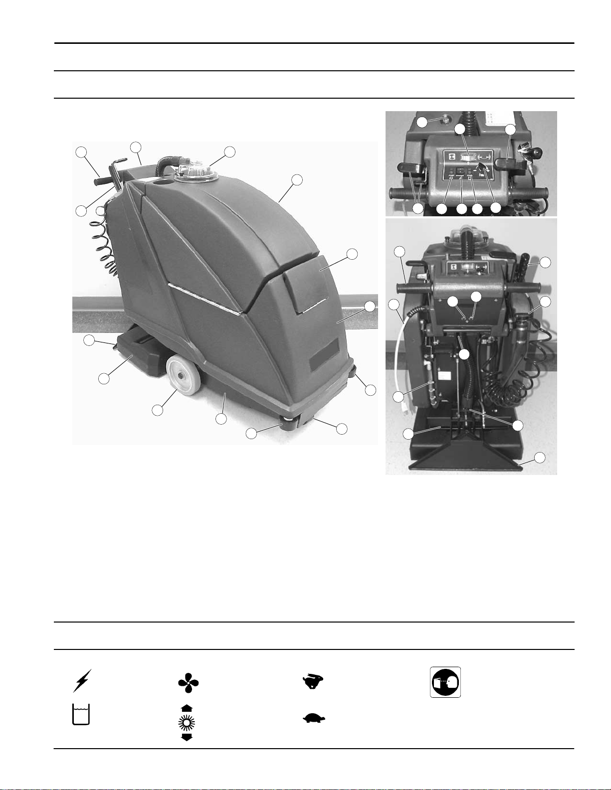
MACHINE COMPONENTS 5. . . . . . . . . . . . . . . . . . .
CONTROL PANEL SYMBOLS 5. . . . . . . . . . . . . . .
SETUP AND OPERATION 6. . . . . . . . . . . . . . . . . . .
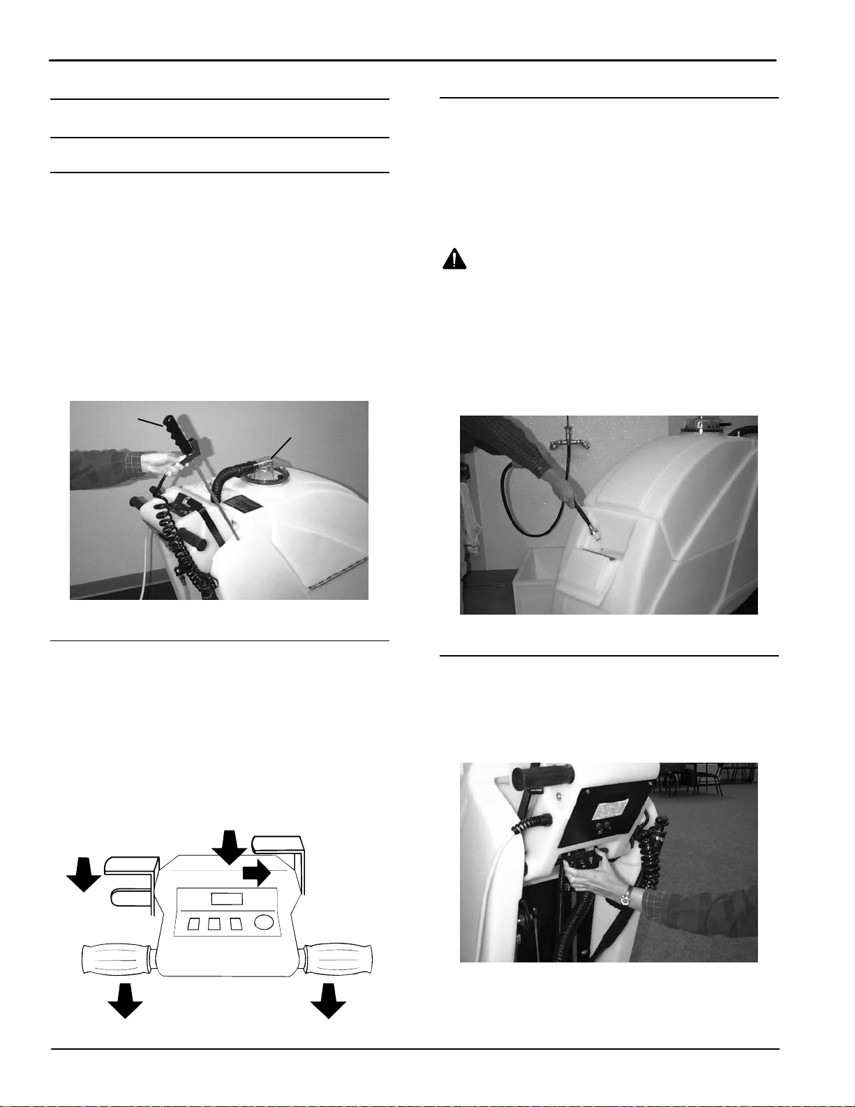
MACHINE INSTALLATION 6. . . . . . . . . . . . . . . .
MANEUVERING MACHINE WITHOUT
USE OF POWER 6. . . . . . . . . . . . . . . . . . . . . . . .
FILLING SOLUTION TANK 6. . . . . . . . . . . . . . .
ADJUSTING CONTROL GRIP HEIGHT 6. . . .
CONNECTING MACHINE TO
POWER SOURCE 7. . . . . . . . . . . . . . . . . . . . . . .
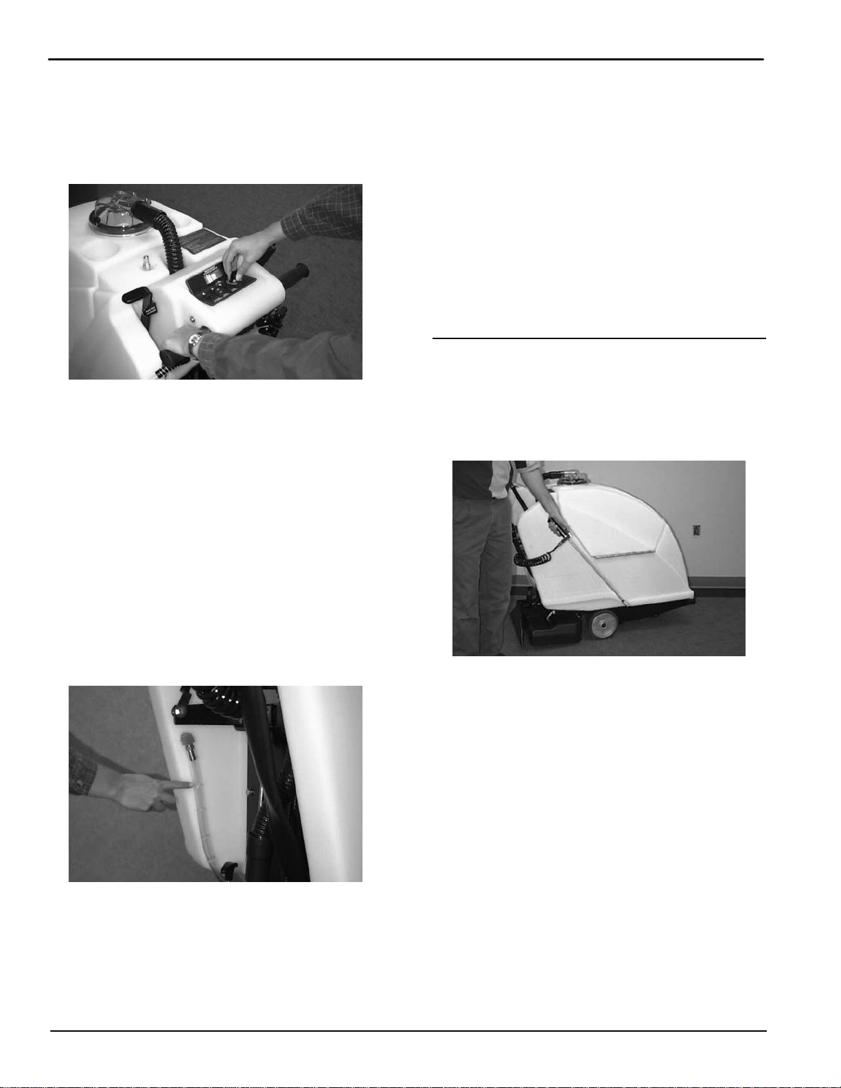
PRE–OPERATION CHECKS 7. . . . . . . . . . . . . .
CLEANING CARPET 7. . . . . . . . . . . . . . . . . . . . .
OPERATING PRE–SPRAY WAND 8. . . . . . . . .
ADJUSTING BRUSH HEIGHT 9. . . . . . . . . . . .
CIRCUIT BREAKERS 9. . . . . . . . . . . . . . . . . . . .
ACCESSORY TOOL SETUP AND
OPERATION (OPTION) 9. . . . . . . . . . . . . . . . . . . . . .
DRAINING TANKS 10. . . . . . . . . . . . . . . . . . . . . . . . . .
MACHINE MAINTENANCE 10. . . . . . . . . . . . . . . . . .
DAILY MAINTENANCE 10. . . . . . . . . . . . . . . . . . .
WEEKLY MAINTENANCE 11. . . . . . . . . . . . . . . .
MONTHLY MAINTENANCE 11. . . . . . . . . . . . . . .
QUARTERLY MAINTENANCE 12. . . . . . . . . . . .
ADJUSTING DRIVE BELT 12. . . . . . . . . . . . . . . .
TRANSPORTING MACHINE 12. . . . . . . . . . . . . . . . .
STORING MACHINE 13. . . . . . . . . . . . . . . . . . . . . . . .
RECOMMENDED STOCK ITEMS 13. . . . . . . . . . . . .
TROUBLE SHOOTING 13. . . . . . . . . . . . . . . . . . . . . .
SPECIFICATIONS 15. . . . . . . . . . . . . . . . . . . . . . . . . .
ELECTRICAL DIAGRAMS 16. . . . . . . . . . . . . . . . . . .
PARTS LIST 18. . . . . . . . . . . . . . . . . . . . . . . . . . . . . . .
RECOVERY TANK GROUP 18. . . . . . . . . . . . . . .
SOLUTION TANK GROUP 20. . . . . . . . . . . . . . . .
DRIVE WHEEL GROUP 22. . . . . . . . . . . . . . . . . .
REAR PANEL GROUP 24. . . . . . . . . . . . . . . . . . .
CONTROL CONSOLE GROUP 26. . . . . . . . . . .
PICK-UP HEAD GROUP 28. . . . . . . . . . . . . . . . .
BRUSH BASE GROUP 30. . . . . . . . . . . . . . . . . . .
PLUMBING GROUP 32. . . . . . . . . . . . . . . . . . . . .
PUMP BREAKDOWN 34. . . . . . . . . . . . . . . . . . . .
OPTIONS 35. . . . . . . . . . . . . . . . . . . . . . . . . . . . . . . . . .
SOLUTION AND VACUUM HOSES 35. . . . . . . .
330mm (13 in) LOW PRESSURE
FLOOR TOOL 36. . . . . . . . . . . . . . . . . . . . . . . . . . .
406mm (16 in) LOW PRESSURE
FLOOR TOOL 38. . . . . . . . . . . . . . . . . . . . . . . . . . .
127 mm (5 in) HAND TOOL 40. . . . . . . . . . . . . . .
76 mm (3 in) CREVICE TOOL 40. . . . . . . . . . . . .
LOW PRESSURE UPHOLSTERY TOOL 41. . .
Home
Find...
Go To..
Home
Find...
Go To..

OPERATION
SCX-2800 (08–03) 3
SAFETY PRECAUTIONS
This machine is intended for commercial use. It is
designed exclusively to clean carpets in an indoor
environment and is not constructed for any other
use. Use only recommended accessory tools and
commercially available carpet cleaners intended
for machine application.
All operators must read, understand and practice
the following safety precautions.
The following warning alert symbol and the “FOR
SAFETY”heading are used throughout this manual as
indicated in their description:
WARNING: To warn of hazards or unsafe
practices which could result in severe personal
injury or death.
FOR SAFETY: To identify actions which must be
followed for safe operation of equipment.
Failure to follow these warnings may result in:
personal injury, electrocution, electrical shock,
fire or explosion.
WARNING: Do Not Use Flammable Liquids Or
Operate Machine In Or Near Flammable Liquids,
Vapors Or Combustible Dusts.
This machine is not equipped with explosion
proof motors. The electric motors will spark upon
start up and during operation which could cause a
flash fire or explosion if machine is used in an
area where flammable vapors/liquids or
combustible dusts are present.
WARNING: Do Not Pick Up Flammable
Materials Or Reactive Metals.
WARNING: Do Not Operate With Damaged
Power Cord. Do Not Modify Plug. Unplug power
Cord Before Servicing Machine.
If the supply cord is damaged or broken, it must
be replaced by the manufacturer or it’s service
agent or a similarly qualified person in order to
avoid a hazard.
WARNING: Do Not Use Outdoors. Do Not
Expose To Rain. Store Indoors.
The following information signals potentially
dangerous conditions to the operator or
equipment:
FOR SAFETY:
1. Do not operate machine:
–With flammable liquids or near flammable
vapors as an explosion or flash fire may
occur.
–Unless trained and authorized.
–Unless operator manual is read and
understood.
–Unless cord is properly grounded.
–With damaged cord or plug.
–If not in proper operating condition.
–In outdoor areas.
–In standing water.
–With the use of additional extension cords.
Only use manufacturer’s extension cord
equipped with machine which has proper
capacity and is grounded.
2. Before operating machine:
–Make sure all safety devices are in place
and operate properly.
3. When using machine:
–Do not run machine over cord.
–Do not pull machine by plug or cord.
–Do not pull cord around sharp edges or
corners.
–Do not unplug by pulling on cord.
–Do not stretch cord.
–Do not handle plug with wet hands.
–Keep cord away from heated surfaces.
–Go slow on inclines and slippery surfaces.
–Use care when reversing machine.
–Report machine damage or faulty
operation immediately.
–Never allow children to play on or around.
–Follow mixing and handling instructions
on chemical containers.
4. Before leaving or servicing machine:
–Stop on level surface.
–Turn off machine.
–Unplug cord from wall outlet.
Home
Find...
Go To..
Home
Find...
Go To..

OPERATION
4SCX-2800(08–03)
5. When servicing machine:
–Unplug cord from wall outlet.
–Avoid moving parts. Do not wear loose
jackets, shirts, or sleeves.
–Block machine tires before jacking up.
–Use hoist or jack that will support the
weight of the machine.
–Use manufacturer supplied or approved
replacement parts.
–All repairs must be performed by a
qualified service person.
–Do not modify the machine from it’s
original design.
6. When transporting machine:
–Turn machine off.
–Get assistance when lifting machine.
–Unplug cord from wall outlet.
–Use a recommended ramp when
loading/unloading into/off truck or trailer.
–Use tie–down straps to secure machine to
truck or trailer.
GROUNDING INSTRUCTIONS
Machine must be grounded. If it should
malfunction or breakdown, grounding provides a
path of least resistance for electrical current to
reduce the risk of electrical shock. This machine
is equipped with a cord having an
equipment–grounding conductor and grounding
plug. The plug must be plugged into an
appropriate outlet that is properly installed in
accordance with all local codes and ordinances.
Do not remove ground pin; if missing, replace
plug before use.
Grounded
3 Hole Outlet
Ground Pin
WARNING LABEL
The warning label appears on the machine in the
location indicated. Replace label if it becomes
damaged or illegible.
WARNING LABEL –LOCATED ON
TOP OF THE SOLUTION TANK.
Home
Find...
Go To..
Home
Find...
Go To..

OPERATION
SCX-2800 (08–03) 5
MACHINE COMPONENTS
17 20
1918
13 15
14
16
22 23
3
24
21
27 28
29
25
26
2
5
6
2
3
8
10
8
11
4
7
12
1
9
30
1. Control Console
2. Control Grips
3. Prespray Wand
4. Recovery Tank Dome
5. Recovery Tank
6. Solution Tank Fill Door
7. Solution Tank
8. Wall Rollers
9. Front Caster
10. Inline Solution Filter Strainer
11. Non–Marking Drive Wheels
12. Brush Base
13. Accessory Solution Hose Coupler
14. Brush Pressure Meter
15. Reverse Release Lever
16. Brush Lever Raise/Lower
17. Vacuum ON/OFF Switch
18. Main ON/OFF Switch
19. Pump ON/OFF Switch
20. Speed Control Knob
21. Power Cord Pigtail
22. Brush Motor Circuit Breaker
23. Drive Motor Circuit Breaker
24. Recovery Tank Drain Hose
25. Adjustable Control Console Levers
26. Solution Tank Level Indicator
27. Spray Bar
28. Brush Height Adjustment Knob
29. Vacuum Pick-Up Head
CONTROL PANEL SYMBOLS
Main
Power Vacuum
Brush
Pressure
Fast
Speed
Slow
Speed
Read Manual
Before Operating
Pump
Home
Find...
Go To..
Home
Find...
Go To..

OPERATION
6SCX-2800(08–03)
SETUP AND OPERATION
MACHINE INSTALLATION
ATTENTION: To prevent damage to machine when
uncrating, do not attempt to drive or roll off skid.
Carefully lift machine with assistance or use a
ramp.
Your new machine requires very little setup.
1. Place recovery tank dome on top of solution tank
and secure with two thumbscrews (Figure 1).
2. Insert black vacuum hose into dome opening.
3. Install pre-spray wand into opening on right side of
tank, next to control housing (Figure 1).
PRE-SPRAY
WAND RECOVERY TANK
DOME
FIG. 1
MANEUVERING MACHINE WITHOUT USE OF
POWER
Your machine will glide easily across floor by pushing
machine forward (without power). To pull machine
backwards, pull reverse release lever backwards
(arrow A) and to the right to latch (arrow B). This
allows the machine to pull back easily. Be certain
brush is raised before transporting. To raise brush, pull
brush lever backwards (arrow C) until it latches
(Figure 2). A
B
C
FIG. 2
FILLING SOLUTION TANK
Open fill port door at front of machine and fill with 106
liters (28 gal) of hot water, 60_C (140_F) maximum,
and add a recommended liquid cleaning solution to
proper dilution ratio (Figure 3).
FOR SAFETY: When using machine, follow mixing
instructions on chemical containers.
WARNING: Do Not Use Flammable Liquids Or
Operate Machine In Or Near Flammable Liquids,
Vapors Or Combustible Dusts.
ATTENTION: If using powered cleaning chemicals,
mix prior to adding. Wait until completely
dissolved before pouring into solution tank.
ATTENTION: Always use separate buckets to fill
and empty machine. Dirty water in solution tank
will clog solution pump system.
FIG. 3
ADJUSTING CONTROL GRIP HEIGHT
Adjust control grip height to a comfortable operating
height (three settings). To adjust, squeeze two levers
under console together to raise or lower control grip
(Figure 4).
FIG. 4
Home
Find...
Go To..
Home
Find...
Go To..

OPERATION
SCX-2800(08–03) 7
CONNECTING MACHINE TO POWER SOURCE
1. Connect equipped extension cord to short pigtail
cord on machine.
2. Plug extension cord into a grounded power outlet
(Figure 5).
FOR SAFETY: Do not operate machine unless
cord is properly grounded.
FOR SAFETY: Do not operate machine with the
use of additional extension cords. Only use
manufacturer’s extension cord equipped with
machine which has proper capacity and is
grounded.
Grounded
3 Hole Outlet
Ground Pin
FIG. 5
WARNING: Do Not Operate With Damaged
Power Cord. Do Not Modify Plug. Unplug power
Cord Before Servicing Machine.
If the supply cord is damaged or broken, it must
be replaced by the manufacturer or it’s service
agent or a similarly qualified person in order to
avoid a hazard.
3. Attach belt clip to power cord and to your belt
(Figure 6).
FIG. 6
PRE–OPERATION CHECKS
1. Vacuum the floor and remove any debris.
2. Inspect the power cord for damage. Replace
immediately if damaged.
3. Check that the spray bar is installed.
4. Inspect the spray tips for proper spray pattern
(See MACHINE MAINTENANCE).
CLEANING CARPET
FOR SAFETY: Do not operate machine unless
operator manual is read and understood.
WARNING: Do Not Pick Up Flammable
Materials Or Reactive Metals.
WARNING: Do Not Use Flammable Liquids Or
Operate Machine In Or Near Flammable Liquids,
Vapors Or Combustible Dusts.
1. Turn on main power switch.
2. Turn vacuum switch on.
3. Lower brush by depressing thumb latch and
moving lever forward (Figure 7).
FIG. 7
4. Turn pump switch on.
NOTE: Pump and brush are activated by the control
grips.
Home
Find...
Go To..
Home
Find...
Go To..

OPERATION
8SCX-2800(08–03)
5. To begin cleaning, rotate control grips forward and
adjust speed control knob. For deep cleaning of
heavily soiled carpet, operate at a pace of 15 M
(50 ft) per minute. For light or interim cleaning,
operate at a pace of 30 M (100 ft) per minute.
(Figure 8).
FIG. 8
6. Observe brush pressure meter while cleaning, it
should read in the “Best Cleaning Results”range
(See ADJUSTING BRUSH HEIGHT).
7. Watch level of foam build-up in recovery tank. If
excessive foam appears, pour a quality defoamer
chemical into recovery tank.
ATTENTION: Do not allow foam to enter float
shut–off screen. Foam will damage vacuum motor.
Damage caused by foam is not covered by
warranty.
8. Turn pump switch off just before stopping to
vacuum up excess solution.
9. Check remaining solution in solution tank when
cleaning. To check, look at solution tank level
indicator at rear of machine. Each mark on hose
equals 22 Liters (5 gals) of solution (Figure 9).
FIG. 9
10. To pull machine backwards, engage reverse lever.
12. Work away from the wall outlet and power cord to
prevent cord damage.
FOR SAFETY: When using machine, do not run
machine over cord, do not pull machine by plug
or cord, do not pull cord around sharp edges or
corners, do not unplug by pulling on cord and do
not handle plug with wet hands.
13. To stop the machine, position the machine on a
level surface and gradually release the control
grips.
14. After cleaning, perform the Daily Maintenance
procedures (See MACHINE MAINTENANCE).
OPERATING PRE–SPRAY WAND
When cleaning, pre–spray traffic areas and spots
using built–in spray wand. To activate wand, turn on
main power and pump switches. Remove wand from
holder, unlock trigger and spray where needed
(Figure 10).
FIG. 10
Home
Find...
Go To..
Home
Find...
Go To..

OPERATION
SCX-2800(08–03) 9
ADJUSTING BRUSH HEIGHT
1. Lower brush.
2. Rotate speed control knob to slowest setting.
3. Turn main power switch on.
4. Rotate control grips forward and hold them.
5. While reading brush pressure meter, turn brush
height adjustment knob until meter reads in the
“Best Cleaning Results”range (Figure 11).
FIG. 11
CIRCUIT BREAKERS
The machine is equipped with two circuit breakers
located on control housing at rear of machine.
1. Brush motor is protected by a 1.5 amp. circuit
breaker. If breaker should trip, adjust brush height
or remove any obstruction in brush. Reset breaker
button.
FOR SAFETY: When leaving or servicing machine,
turn off machine and unplug from wall outlet.
2. Drive motor is protected by a 2.5 amp. circuit
breaker. If breaker trips, drive motor has been
overstressed or there is an electrical short. Allow
motor to cool and push circuit breaker button to
reset or contact service center.
NOTE: When cleaning on inclines, always clean
moving downward, never upward. Never climb inclines
that exceed 5 degrees, machine damage may occur.
ACCESSORY TOOL SETUP AND
OPERATION (OPTION)
The optional accessory tools allow you to clean
upholstery and areas that the machine is unable to
clean, such as alcoves, stairs, corners and small
rooms.
For a complete list of accessory tools see the
OPTIONS section in this manual
NOTE: When cleaning upholstery, always check
cleaning instructions sewn in the furniture by
manufacturer.
1. Vacuum area before cleaning.
2. Disconnect vacuum hose from recovery dome and
replace with optional extension vacuum hose.
Connect optional solution hose to quick disconnect
located on top of tank. Then connect optional
accessory tool to hoses (Figure 13).
FIG. 12
3. Turn on “Main”, “Vacuum”and “Pump”switches.
4. To clean, place tool on area to be cleaned,
squeeze trigger and pull tool backwards
(Figure 14).
FIG. 13
WARNING: Flammable materials or reactive
metals can cause an explosion or fire. Do not pick
up.
Home
Find...
Go To..
Home
Find...
Go To..

OPERATION
10 SCX-2800(08–03)
5. Overlap strokes to avoid streaking.
NOTE: When cleaning upholstery, use as little
cleaning solution as possible and avoid over wetting.
DRAINING TANKS
When finished cleaning, the recovery tank and solution
tank should be drained and cleaned.
FOR SAFETY: Before leaving or servicing
machine, turn off machine and unplug cord from
wall outlet.
1. To drain recovery tank, push machine to a drain
sink or floor drain and unhook drain hose from rear
of machine. Unscrew T-handle from drain hose
and drain tank (Figure 15).
FIG. 14
2. Remove recovery tank dome and rinse out tank.
You can use the spray wand to rinse out recovery
tank. Be careful not to spray water into standpipe
screen (Figure 15).
FIG. 15
3. To drain solution tank, place machine over a drain
sink or floor drain, pull solution tank level indicator
hose off hose barb and drain (Figure 16).
FIG. 16
MACHINE MAINTENANCE
To keep machine in good working condition, simply
follow machine’s daily, weekly and monthly
maintenance procedures.
FOR SAFETY: Before leaving or servicing
machine, stop on level surface, turn off machine
and unplug cord from wall outlet.
ATTENTION: Contact an Authorized Service
Center for machine repairs. Machine repairs
performed by other than an authorized person will
void the warranty
DAILY MAINTENANCE
(EVERY 4 HOURS OF USE)
1. Drain and rinse out recovery tank and recovery
dome.
2. Remove float shut-off screen and clean. Screen is
located in recovery tank (Figure 18).
FIG. 17
Home
Find...
Go To..
Home
Find...
Go To..

OPERATION
SCX-2800(08–03) 11
3. Drain solution tank. To drain, disconnect the
solution tank level indicator hose at rear of
machine (Figure 18).
FIG. 18
4. Remove any carpet strands or other debris from
brush.
5. Remove any debris lodged inside vacuum pick-up
head.
6. Inspect pigtail cord, cord grip and detachable
power cord for damage. Replace immediately if
damaged.
7. Clean machine housing with an all purpose
cleaner and damp cloth.
WEEKLY MAINTENANCE
(EVERY 20 HOURS OF USE)
1. Inspect spray tips for proper spray pattern:
a. Engage the reverse release lever to keep
machine stationary (Figure 19).
FIG. 19
b. Lower brush/pickup head and remove
detachable spray bar from brush base. Do not
disconnect bar from quick coupler (Figure 20).
Raise brush after removing spray bar.
c. Turn the main power and pump switches on.
d. Holding the spray bar off the floor, briefly rotate
control grips and observe spray pattern. Pattern
should fan out evenly across the width of the
spray bar (Figure 20).
FIG. 20
e. Clean or replace defective twist–out spray tips
if necessary (See MONTHLY MAINTENANCE).
2. Tighten hose cuffs and inspect hose for damage.
3. Remove bowl filter located underneath machine at
front and clean screen. Make sure solution tank is
empty before removing filter (Figure 21).
FIG. 21
MONTHLY MAINTENANCE
(EVERY 80 HOURS USE)
1. Flush pump system with an acetic acid solution to
dissolve alkaline chemical buildup. Follow
instructions below:
a. Pour 1L (24 oz.) of an acetic acid solution in
solution tank with 13L (3 gal) warm water.
FOR SAFETY: When using machine, follow mixing
and handling instructions on chemical containers.
Home
Find...
Go To..
Home
Find...
Go To..

OPERATION
12 SCX-2800(08–03)
b. Place machine over floor drain and engage
reverse release lever.
c. Operate pump for 2 to 3 minutes.
d. Allow solution to remain in system overnight in
above freezing temperatures.
e. Next day, drain solution and run 13L (3 gal) of
clean water through system to flush out
impurities.
2. Remove spray bar from machine by disconnecting
quick coupler. Remove quick release spray tips
from spray bar and soak spray tips in an acetic
acid solution for up to six hours. Do not use
pointed objects to unplug tips, damage will occur
(Figure 22).
FIG. 22
3. Lubricate wheels and caster with a water resistant
grease.
4. Inspect machine for water leaks.
5. Inspect machine for loose screws.
6. Check tension of drive belt. Drive belt must be
properly adjusted to eliminate any slippage. (See
ADJUSTING DRIVE BELT).
NOTE: Belt may slip if wet.
QUARTERLY MAINTENANCE
(EVERY 250 HOURS OF USE)
Inspect motors for carbon brush wear. Replace
brushes when worn to a length of 10 mm (0.38 in) or
less. Contact an Authorized Service Center for carbon
brush inspection.
FOR SAFETY: When servicing machine, all repairs
must be performed by a qualified service person.
ADJUSTING DRIVE BELT
FOR SAFETY: When servicing machine, unplug
cord from wall outlet.
1. Carefully lay machine on its left side.
2. Loosen (4) bolts on drive motor (Figure 23).
3. Loosen locknut on belt tension bolt.
4. Turn belt tension bolt clockwise to tighten belt.
5. Retighten locknut on belt tension bolt. Do not over
tighten belt; belt should flex 12.7 mm (0.50 in) at
center. For proper adjustment, belt should
represent diagram below.
BELT TENSION BOLT
LOOSEN 4 BOLTS
LOCKNUT
FIG. 23
TRANSPORTING MACHINE
When transporting the machine by use of trailer or
truck, be certain to follow tie–down procedures below:
FOR SAFETY: When using machine, go slow on
inclines and slippery surfaces.
1. Raise brush base.
2. Load the machine using a recommended loading
ramp.
3. Position the front of the machine up against the
front of the trailer or truck. Once machine is
positioned, lower the brush base and disengage
the reverse release lever.
4. Place a block behind each drive wheel to prevent
machine from rolling.
5. Place tie–down straps over the top of the machine
to prevent it from tipping. It may be necessary to
install tie–down brackets to the floor of your trailer
or truck.
FOR SAFETY: When transporting machine, use a
recommended ramp when loading/unloading
into/off truck or trailer, use tie–down straps to
secure machine to truck or trailer.
Home
Find...
Go To..
Home
Find...
Go To..

OPERATION
SCX-2800(08–03) 13
STORING MACHINE
1. Drain and rinse tanks thoroughly.
2. Store the machine in a dry area with the brush
base in the raised position.
3. Remove the recovery tank dome to promote air
circulation.
ATTENTION: If storing the machine in freezing
temperatures, be certain to drain tanks, purge
pump and remove the solution tank filter located
under the machine at front. Damage due to
freezing temperatures is not covered by warranty.
WARNING: Do Not Use Outdoors. Do Not
Expose To Rain. Store Indoors.
RECOMMENDED STOCK ITEMS
Refer to Standard Parts section for recommended
stock items. Stock Items are clearly identified with a
Bullet preceding the parts description. See example
below:
TROUBLE SHOOTING
PROBLEM CAUSE SOLUTION
No power Faulty main power switch. Contact Service Center.
Loose power cord connection Connect power cord.
Faulty power supply cord. Replace power supply cord.
Building circuit breaker has tripped. Determine cause and reset circuit
breaker in building.
Brush motor does not operate Pump switch is not activated. Turn on pump switch.
Control grips are not rotated. Rotate control grips.
Brush circuit breaker has tripped. Remove obstruction from brush and
reset brush circuit breaker button.
Faulty brush motor or wiring. Contact Service Center.
Carbon brushes worn. Contact Service Center.
“Roll Switch 1”(left side) faulty or
needs adjustment. Contact Service Center.
Loose or broken belt. Replace, or contact Service Center.
Brush motor operates, but brush Loose or broken brush drive belt. Tighten or replace belt.
does not spin Loose set screws on belt pulleys. Tighten set screws.
Vacuum motor does not operate Vacuum switch not turned on. Turn on vacuum switch.
Vacuum motor does not operate Faulty vacuum switch or wiring. Contact Service Center.
Faulty vacuum motor or wiring. Contact Service Center.
Vacuum motor thermal overload acti-
vated. Remove obstruction and wait 20 min-
utes for motor to cool.
Home
Find...
Go To..
Home
Find...
Go To..

OPERATION
14 SCX-2800(08–03)
TROUBLE SHOOTING –continued
PROBLEM CAUSE SOLUTION
Poor vacuum recovery Recovery tank is full. Empty recovery tank.
Float shut–off screen inside recovery
tank is clogged. Remove screen and clean.
Pickup head is clogged with debris. Remove debris, use coat hanger.
Vacuum hose connections/cuffs are
loose or hose is defective. Push hose cuffs firmly onto connec-
tions. Replace hose if damaged.
Vacuum hose is clogged with debris. Remove clogged debris.
Dome gasket is defective. Replace gasket.
Drain hose plug is loose. Tighten drain plug.
Recovery tank dome is loose. Tighten dome screws.
Vacuum motor is loose. Contact Service Center.
Reverse release lever is hard to
engage Belt tension too tight. Readjust belt tension (See Mainte-
nance instructions).
Pre–spray wand does not spray “Main”and “Pump”switches not
turned on. Turn “Main”and “Pump”switches on.
Trigger locked on wand. Unlock trigger.
Spray tip on wand plugged. Remove spray tip and clean with an
acetic acid solution.
Bowl filter screen plugged. See Weekly Maintenance
Loose or broken wiring. Contact Service Center.
Faulty MAIN or PUMP switch. Contact Service Center.
Faulty solution pump. Contact Service Center.
Machine does not spray solution MAIN switch is not turned on. Turn on MAIN switch.
PUMP switch is not turned on. Turn on PUMP switch.
Control grips not twisted. Twist control grips forward to start
spray, brush and drive motors.
Bowl filter screen plugged. See Weekly Maintenance.
Spray tips plugged. See Monthly Maintenance.
Loose or broken wiring. Contact Service Center.
Faulty solenoid valve. Contact Service Center.
Faulty MAIN or PUMP switch. Contact Service Center.
Machine does not spray solution Roll Switch 1 faulty or needs adjust-
ment. Contact Service Center.
Faulty solution pump. Contact Service Center.
Home
Find...
Go To..
Home
Find...
Go To..

OPERATION
SCX-2800(08–03) 15
TROUBLE SHOOTING –continued
PROBLEM CAUSE SOLUTION
Machine does not move when Reverse release lever engaged. Disengage reverse release lever.
rotating control grips MAIN switch not turned on. Turn on MAIN switch.
Speed control knob turned to slowest
setting. Turn speed control knob to desired
setting.
2.5 amp. circuit breaker tripped. Push breaker button to reset.
Loose drive belt. Tighten belt (See Maintenance).
Broken drive belt. Replace belt (See Maintenance).
Wet drive belt. Dry belt off.
Loose or broken wiring. Contact Service Center.
Roll Switch 1 or 2 faulty or needs ad-
justment. Contact Service Center.
Speed Control Board faulty or needs
adjustment. Contact Service Center.
Faulty drive motor or wiring. Contact Service Center.
Worn carbon brushes in drive motor. Contact Service Center.
SPECIFICATIONS
MODEL SCX-2800
LENGTH 1295 mm (51 in)
WIDTH 559 mm (22 in)
HEIGHT 1092 mm (43 in)
WEIGHT 109 Kg (241 lb)
SOLUTION TANK CAPACITY 106 L (28 Gal)
RECOVERY TANK CAPACITY 68 L (18 Gal)
SPEED CONTROL Variable Fwd.
CLEANING SPEED (MAX) 697 m2(7,500 sq ft) per hour
CLEANING PATH WIDTH 559 mm (22 in)
SOLUTION PUMP 6.9 bar (100 psi) max., 120V, 1A, 1 gpm
BRUSH MOTOR .16hp, 1800 rpm, 120V, 1A, 90W
VACUUM MOTOR 2hp, 3–stage 5.7 in, 120V, 13A
WATER LIFT / AIR FLOW 3480 mm (137 in) / 2.86 m3h (101 cfm)
DECIBEL RATING AT OPERATOR’S EAR, INDOORS ON
CARPET 81dB(A)
POWER CORD LENGTH 23 m (75 ft)
Home
Find...
Go To..
Home
Find...
Go To..

ELECTRICAL DIAGRAMS
SCX-2800 (08–03)
16
120V WIRING DIAGRAM
VACUUM
SWITCH PUMP
SWITCH
4
1
1
5
5
2
13
4
2.5 AMP
CIRCUIT
BREAKER
(DRIVE)
1.5 AMP
CIRCUIT
BREAKER
(BRUSH)
6
CONDUIT TO
CHASSIS
7
3
3
3
3
15
15
16
9
8
+
SOLUTION
PUMP
BRUSH
MOTOR
VACUUM
MOTOR
SOLENOID
DRIVE
MOTOR
ROLL
SWITCH 2
ROLL
SWITCH 1
BRUSH MOTOR
CORD
POWER
CORD BLACK
BRUSH HEIGHT
METER
MAIN
SWITCH
SPEED CONTROL BOARD
AC AC A+ A/F HI W LO
5 kW
POTENTIOMETER
WHITE
BLACK
BLACK
GREEN
WHITE
BLACK
BLACK
BLACK
BLACK
GREEN
BLACK
BLACK
WHITE WHT / ORNGE
WHT / ORNGE
WHITE
RED
ORANGE
BLACK
WHITE
PINK
GRAY
BLACK
WHITE
WHITE
BLUE
WHT/RED
RED
GRAY BLACK
PINK BLACK
BLUE
WHITE
GREEN
GRN / YLW
ORANGE
WHT / ORNGE BLACK
GREEN
RED
BLACK
GREEN
GREEN
AC
AC
WHITE
GREEN
GREEN
GREEN
BLACK
WHITE
RED
WHITE
RED
ORANGE
WHITE
WHITE
WHT / RED
BLACK
WHT / RED
BLUE
PINK
GRAY
RED
WHT / ORNGE
ORANGE
BLACK
GREEN WHITE
BLACK BLACK
WHITE
GREEN
BLACK
WHITE
GREEN
BLACK
Home
Find...
Go To..
Home
Find...
Go To..

ELECTRICAL DIAGRAMS
17
SCX-2800 (08–03)
120V LADDER DIAGRAM
DRIVE
MOTOR
+
POTENTIOMETER
5 KW
LINE 1 LINE 2
MAIN
SWITCH
VACUUM
SWITCH
ROLL
SWITCH 1
ROLL
SWITCH 2
SPEED CONTROL BOARD
TERMINALS
PUMP
SWITCH
SOLENOID
AC AC A+ A/F HI W LO
SOLUTION
PUMP
CIRCUIT
BREAKER
2.5AMP
VACUUM
MOTOR
BRUSH
MOTOR
CIRCUIT
BREAKER
1.5AMP
Home
Find...
Go To..
Home
Find...
Go To..

PARTS LIST
SCX-2800(08–03)
18
RECOVERY TANK GROUP
1
2
3
4
5
6
78
9
10
11
12
13
14
16
17
20
19
15
22 21
23
18
24
26
25
35
27
32
33
31
30
34
29
28
Home
Find...
Go To..
Home
Find...
Go To..

PARTS LIST
SCX-2800(08–03) 19
RECOVERY TANK GROUP
REF PART # DESCRIPTION QTY.
∇100162 ASM., STANDPIPE W/NIPPLE 1
Y1 100759 STANDPIPE 1
Y2 606088 NIPPLE, 1–1/2 PVC 1
3 101714 DGASKET, WASTE AIR CHAMBER 1
4 210240 NUT, FLANGED METAL 1
5 180613 DFLOAT, SHUT–OFF SCREEN 1
6 160413 DHOSE, VAC INTAKE 1
∇700683 ASM, DOME W/ELBOW 1
Y7 100112 DOME, VACUUM 1
Y8 120399 LABEL, DO NOT ALLOW FOAM 1
Y9 100042 DGASKET, RECOVERY DOME 1
Y10 240217 KNOB, RND .25–20 BLK 2
Y11 140037 WASHER, .218X.437X.031 NYLON 2
12 608171 TANK, RECOVERY BLUE 1
13 140227 STUD, 1/4–20X5 3
14 100038 DGASKET, VAC MOTOR 5.7 1
∇15 130996 DMOTOR, VAC 5.7/3 STG 120V 1
Y16 130133 TERMINAL, MALE .25 RED 2
Y17 602741 DCARBON BRUSHES 2/PK 1
∇ASSEMBLY
YINCLUDED IN ASSEMBLY
DRECOMMENDED STOCK ITEMS
REF PART # DESCRIPTION QTY.
Y18 130486 DFAN, SHELL 5.7 MOTOR 1
19 41169 NUT, HEX LOCK .25–20 NYLON 3
20 140000 WASHER, FLAT 1/4”3
21 140000 WASHER, FLAT 1/4”9
22 140015 WASHER, LOCK SPLIT 0.31 9
23 02991 SCREW, HEX .31–18X0.75 9
24 230418 HINGE, TANK 1
25 160487 DHOSE, VAC 2”X34”WHT 1
26 140308 CLAMP, HOSE 1–5/16 TO 2–1/4 1
∇701061 DASM., DRAIN HOSE STOPPER 1
Y27 230831 KNOB, DRAIN HOSE 1
Y28 230882 DSTRAP, DRAIN HOSE STOPPER 1
Y29 140056 WASHER, FLAT .38 FENDER 1
Y30 140955 PLUG, DRAIN HOSE 1
31 140921 SLEEVE, DRAIN HOSE 1
32 140072 CLAMP, HOSE 1–9/16”STEPLESS 2
33 160414 HOSE, DRAIN 1
34 140307 CLAMP, HOSE 3/4 TO 1–3/4 1
35 100029 GASKET, TUBE 1
Home
Find...
Go To..
Home
Find...
Go To..

PARTS LIST
SCX-2800(08–03)
20
SOLUTION TANK GROUP
1
2
3
5
4
7
89
10
11
12
13
14
15
12
16
23
22
24
21 20 19
18 17
25
26
27
28
29
30
32
31
33
34
35
36
37
34
35
36
6
Home
Find...
Go To..
Home
Find...
Go To..
This manual suits for next models
1
Table of contents
Other Castex Scrubber manuals
Popular Scrubber manuals by other brands

CleanFreak
CleanFreak 20B-Z Operator's & parts manual

Sunmax
Sunmax RT-120 Use and Maintenance Instruction

Electrolux Professional
Electrolux Professional WHB5 500H user manual

Truvox International
Truvox International Cimex Cyclone CR38 user manual

Windsor
Windsor VP6 operating instructions

Kärcher
Kärcher BR 55/40 RS manual