Castex PX-1000 Product manual

Operator and Parts Manual
Portable Carpet Extractor
Model No.:
607781
607794 - PAC
PX-1000
608052
Rev. 01 (03-04)
CASTEX CUSTOMER SERVICE:
1--800--365--6625
FAX: 1--800--678--4240
TECHNICAL SUPPORT:
1--800--522--7839 EXT. 5356
TENNANT COMPANY
701 NORTH LILAC DRIVE
MINNEAPOLIS, MN 55422
MAILING ADDRESS:
TENNANT COMPANY
P.O. BOX 1452
MINNEAPOLIS, MN 55440--1452
Home
Find...
Go To..

OPERATION
2PX-1000 (03--04)
This manual is furnished with each new model.
It provides necessary operation and maintenance
instructions and an illustrated parts list.
Read this manual completely and understand the
machine before operating or servicing it.
Use the illustrated Parts Lists to order parts. Before
ordering parts or supplies, be sure to have your
machine model number and serial number handy.
Parts and supplies may be ordered by phone or mail
from any authorized parts and service center,
distributor or from any of the manufacturer’s
subsidiaries.
This machine will provide excellent service. However,
the best results will be obtained at minimum costs if:
SThe machine is operated with reasonable care.
SThe machine is maintained regularly - per the
maintenance instructions provided.
SThe machine is maintained with manufacturer
supplied or equivalent parts.
MACHINE DATA
Please fill out at time of installation for future reference.
Model No.-
Install. Date -
Serial No.-
E1999, 2004 Tennant Company Printed in U.S.A.
Castex is a registered United States trademark of Tennant Company.
TABLE OF CONTENTS
SAFETY PRECAUTIONS 3....................
GROUNDING INSTRUCTIONS 4...........
SAFETY LABEL 4............................
MACHINE COMPONENTS 5...................
MACHINE SETUP 6..........................
MACHINE OPERATION 7.....................
PRE--OPERATION 7.......................
FLOOR TOOL OPERATION 7..............
OPTIONAL HAND TOOL OPERATION 8.....
DRAINING TANKS 8..........................
DRAINING RECOVERY TANK 8............
DRAINING SOLUTION TANK 9.............
MACHINE MAINTENANCE 9..................
DAILY MAINTENANCE 9...................
MONTHLY MAINTENANCE 10...............
QUARTERLY MAINTENANCE 10............
SERVICING MACHINE 10...................
STORING MACHINE 11........................
RECOMMENDED STOCK ITEMS 11.............
TROUBLE SHOOTING 11......................
SPECIFICATIONS 12..........................
MACHINE DIMENSIONS 12....................
ELECTRICAL DIAGRAMS 13...................
PARTS LIST 14...............................
RECOVERY TANK GROUP 14...............
CHASSIS GROUP 16.......................
CONTROL CONSOLE GROUP 18...........
PUMP BREAKDOWN 20....................
OPTIONS 21..................................
127mm (5 in) HAND TOOL GROUP 21........
76mm (3 in) CREVICE TOOL GROUP 21.....
330mm (13 in) LOW PRESSURE WAND
GROUP 22................................
406mm (16 in) LOW PRESSURE WAND
GROUP 24................................
UPHOLSTERY TOOL GROUP 26............
CHEMICALS 26............................
SOLUTION AND VACUUM HOSES GROUP 27
Home
Find...
Go To..

OPERATION
PX-1000 (03--04) 3
SAFETY PRECAUTIONS
This machine is intended for commercial use. It is
designed exclusively to clean carpet and
upholstery in an indoor environment and is not
constructed for any other use. Use only
recommended accessory tools and commercially
available carpet cleaners intended for machine
application.
All operators must read, understand and practice
the following safety precautions.
The following warning alert symbol and the “FOR
SAFETY” heading are used throughout this manual as
indicated in their description:
WARNING: To warn of hazards or unsafe
practices which could result in severe personal
injury or death.
FOR SAFETY: To identify actions which must be
followed for safe operation of equipment.
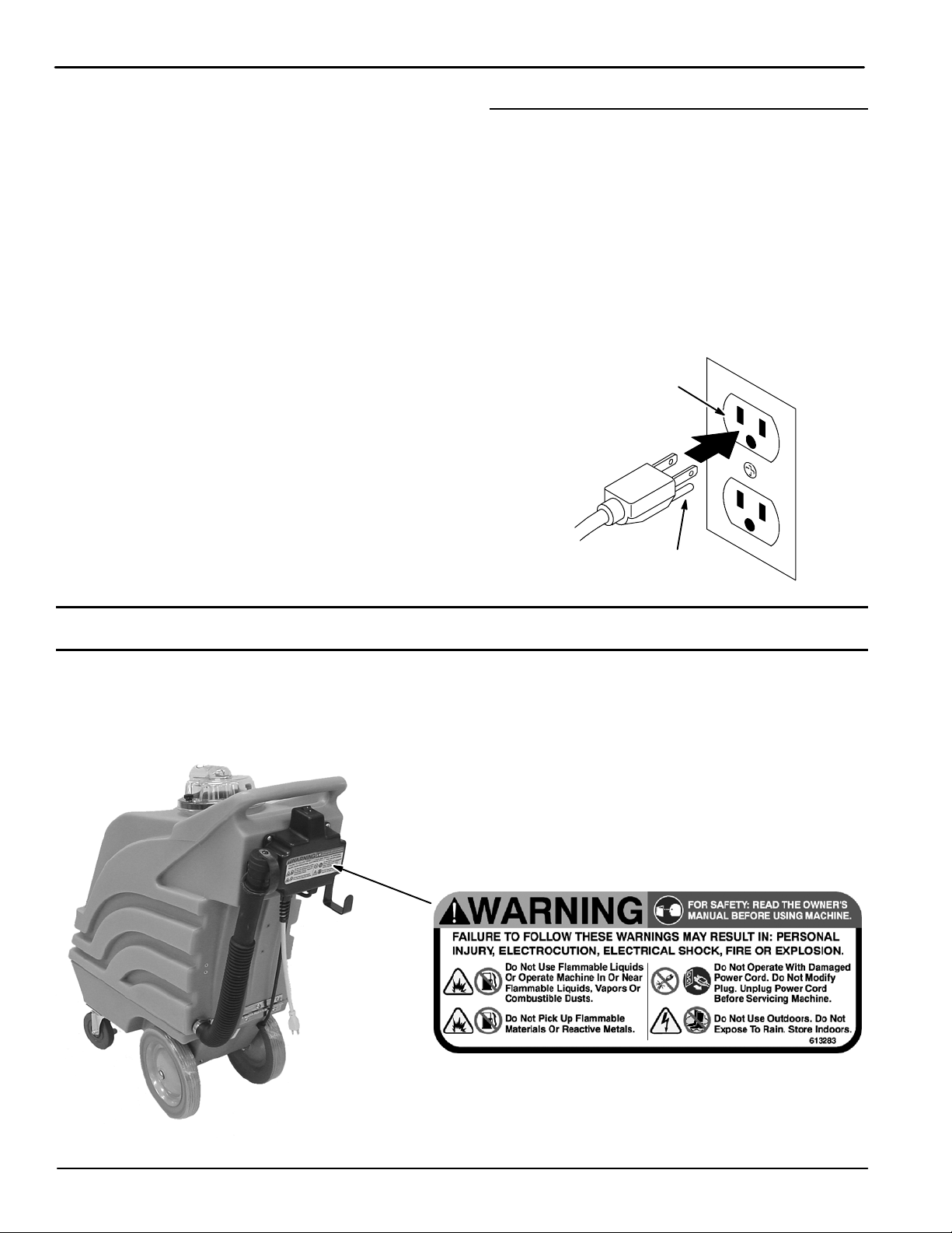
Failure to follow these warnings may result in:
personal injury, electrocution, electrical shock,
fire or explosion.
WARNING: Do Not Use Flammable Liquids Or
Operate Machine In Or Near Flammable Liquids,
Vapors Or Combustible Dusts.
This machine is not equipped with explosion
proof motors. The electric motors will spark upon
start up and during operation which could cause a
flash fire or explosion if machine is used in an
area where flammable vapors/liquids or
combustible dusts are present.
WARNING: Do Not Pick Up Flammable
Materials Or Reactive Metals.
WARNING: Do Not Operate With Damaged
Power Cord. Do Not Modify Plug. Unplug power
Cord Before Servicing Machine.
If the supply cord is damaged or broken, it must
be replaced by the manufacturer or it’s service
agent or a similarly qualified person in order to
avoid a hazard.
WARNING: Do Not Use Outdoors. Do Not
Expose To Rain. Store Indoors.
The following information signals potentially
dangerous conditions to the operator or
equipment:
FOR SAFETY:
1. Do not operate machine:
-- With flammable liquids or near flammable
vapors as an explosion or flash fire may
occur.
-- Unless trained and authorized.
-- Unless operator manual is read and
understood.
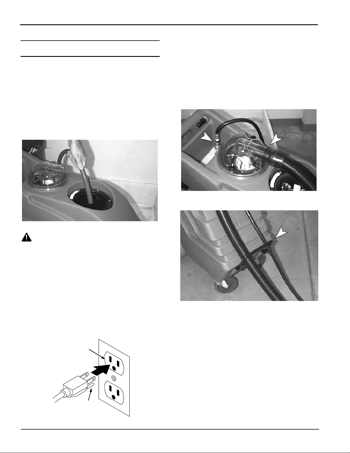
-- Unless cord is properly grounded.
-- With damaged cord or plug.
-- If not in proper operating condition.
-- In outdoor areas.
-- In standing water.
-- With the use of additional extension cords.
Only use manufacturer’s extension cord
equipped with machine which has proper
capacity and is grounded.
2. Before operating machine:
-- Make sure all safety devices are in place
and operate properly.
-- Place wet floor signs as needed.
3. When using machine:
-- Do not run machine over cord.
-- Do not pull machine by plug or cord.
-- Do not pull cord around sharp edges or
corners.
-- Do not unplug by pulling on cord.
-- Do not stretch cord.
-- Do not handle plug with wet hands.
-- Keep cord away from heated surfaces.
-- Report machine damage or faulty
operation immediately.
-- Follow mixing and handling instructions
on chemical containers
-- Never allow children to play on or around.
4. Before leaving or servicing machine:
-- Turn off machine.
-- Unplug cord from wall outlet.
Home
Find...
Go To..

OPERATION
4PX-1000 (03--04)
5. When servicing machine:
-- Unplug cord from wall outlet.
-- Avoid moving parts. Do not wear loose
jackets, shirts, or sleeves.
-- Use manufacturer supplied or approved
replacement parts.
-- All repairs must be performed by a
qualified service person.
-- Do not modify the machine from its
original design.
6. When transporting machine:
-- Get assistance when lifting machine.
-- Unplug cord from wall outlet.
-- Use tie--down straps to secure machine to
truck or trailer.
GROUNDING INSTRUCTIONS
Machine must be grounded. If it should
malfunction or breakdown, grounding provides a
path of least resistance for electrical current to
reduce the risk of electrical shock. This machine
is equipped with a cord having an
equipment--grounding conductor and grounding
plug. The plug must be plugged into an
appropriate outlet that is properly installed in
accordance with all local codes and ordinances.
Do not remove ground pin; if missing, replace
plug before use.
Grounded
3HoleOutlet
Ground Pin
SAFETY LABEL
The safety label appears on the machine in the
location indicated. Replace label if it becomes
damaged or illegible.
WARNING LABEL -- Located on back of machine.
Home
Find...
Go To..

OPERATION
PX-1000 (03--04) 5
MACHINE COMPONENTS
2
36
14
5
1
4
15
13
12
9
10 7
16
8
11
1. Machine Lift Handle
2. Solution Tank
3. Recovery Tank
4. Lockable Casters
5. 254mm (10 in) Stair Climbing Wheels
6. Chemical Bottle Holder
7. Main Power ON/OFF Switch
8. Power Supply Cord Pigtail
9. Recovery Tank Drain Hose
10. Accessory Tool Solution Hose Hookup
11. Accessory Tool Vacuum Hose Hookup
12. 4.6m (15 ft) Vacuum Hose
13. 4.6m (15 ft) Solution Hose
14. 330mm (13 in) Floor Tool (standard)
406mm (16 in) Floor Tool (optional)
15. 7.6m (25 ft) Power Supply Cord
16. Power Supply Cord Hook
Home
Find...
Go To..

OPERATION
6PX-1000 (03--04)
MACHINE SETUP
1. Carefully check carton for signs of damage.
Report damages at once to carrier. The machine
is shipped fully assembled and is ready for use.
2. Remove solution tank lid. Using a hose or bucket,
fill tank with 38L (10 gal) of hot water, 60_C
(140_F) maximum (Figure 1).
NOTE: The water must not be hotter than 60_C
(140_F) or tank damage may occur.
NOTE: If filling with a bucket be certain that bucket is
clean. This will prevent possible solution line clogs.
FIG. 1
WARNING: Do Not Use Flammable Liquids Or
Operate Machine In Or Near Flammable Liquids,
Vapors Or Combustible Dusts.
3. Add a recommended cleaning solution.
FOR SAFETY: When using machine, follow mixing
and handling instructions on chemical containers.
ATTENTION: If using powered cleaning chemicals,
mix prior to adding.
NOTE: If desired, water alone achieves excellent
cleaning results.
4. Replace lid securely after filling.
5. Connect the supplied extension cord to machine.
Plug cord into a grounded wall outlet (Figure 2).
Grounded
3HoleOutlet
Ground Pin
FIG. 2
FOR SAFETY: Do not operate machine unless
cord is properly grounded.
FOR SAFETY: Do not operate machine with the
use of additional extension cords. Only use
manufacturer’s extension cord equipped with
machine which has proper capacity and is
grounded.
6. Connect vacuum hose to recovery dome and
solution hose to quick coupler located in front of
handle (Figure 3).
FIG. 3
7. Route hoses through front lift handle (Figure 4).
FIG. 4
NOTE: Routing hoses through handle will allow easy
machine mobility while operating cleaning tool.
Home
Find...
Go To..

OPERATION
PX-1000 (03--04) 7
8. Attach accessory tool to opposite end of hoses
(Figure 5).
FIG. 5
9. If desired, lock the front casters to keep machine
stationary while cleaning (Figure 6).
FIG. 6
MACHINE OPERATION
FOR SAFETY: Do not operate machine unless
operator manual is read and understood.
PRE--OPERATION
1. Vacuum carpet and remove other debris.
2. Perform MACHINE SETUP procedures.
3. Inspect power cord for damage.
WARNING: Do Not Operate With Damaged
Power Cord. Do Not Modify Plug. Unplug power
Cord Before Servicing Machine.
If the supply cord is damaged or broken, it must
be replaced by the manufacturer or it’s service
agent or a similarly qualified person in order to
avoid a hazard.
FLOOR TOOL OPERATION
1. Activate ON/OFF switch to “ON”.
2. Place floor tool so bottom of stainless steel shoes
are parallel to floor. Squeeze trigger and apply
downward pressure on floor tool head and slowly
pull tool backwards using both hands. Release
trigger 150 mm (6 in) from end of stroke
(Figure 7).
WARNING: Do Not Pick Up Flammable
Materials Or Reactive Metals.
FIG. 7
3. Push floor tool forward over same path with trigger
released when returning for next stroke. Continue
this pull and push method with a slight overlap of
each stroke.
NOTE: For heavily soiled areas, repeat stroke or
change angle of stroke.
4. Check for excessive foam buildup in recovery
tank. Use a recommended foam control solution to
prevent vacuum motor damage.
ATTENTION: Excessive foam buildup will not
activate the float shut-off screen. Vacuum motor
damage may result.
5. When finished cleaning, turn off switch and drain
recovery tank (See DRAINING RECOVERY
TANK).
6. After cleaning, relieve water pressure from
accessory tool before disconnecting hose.
Squeeze trigger for five seconds after turning off
the main power switch.
Home
Find...
Go To..

OPERATION
8PX-1000 (03--04)
OPTIONAL HAND TOOL OPERATION
NOTE: This machine cleans most synthetic
upholstery very well. Extraction in not recommended
for most cottons, silks, wools or natural fiber velvets.
Check cleaning instructions sewn in furniture by
manufacturer for further instructions. Extra caution
should be taken with furniture that has been
reupholstered. Any material under new upholstery may
bleed and discolor new fabric.
NOTE: Vacuum upholstery before cleaning.
1. TEST FABRIC FOR COLORFASTNESS. Pour a
small amount of cleaning solution on a white cloth
and hold damp portion of cloth against an area of
upholstery which is hidden from view. Hold it there
for 60 seconds. If no color transfers to the cloth, it
should be safe to clean. However, always use
your best judgement.
2. Activate ON/OFF switch to ”ON”.
3. Hold tool 150-200 mm (6-8 inches) above fabric
and squeeze trigger to spray cleaning solution
(Figure 8).
FIG. 8
4. Place tool on fabric and slowly pull tool
backwards.
NOTE: Be careful not to over wet upholstery. Overlap
strokes to avoid streaking. Repeat stroke using only
vacuum to get fabric as dry as possible.
WARNING: Do Not Pick Up Flammable
Materials Or Reactive Metals.
ATTENTION: Do not allow water or foam to enter
float shut--off screen in recovery tank.
5. When finished cleaning, turn off switches and
drain recovery tank (See DRAINING RECOVERY
TANK).
6. After cleaning, relieve water pressure from tool
before disconnecting hose. Squeeze trigger for
five seconds after turning main power switch off.
DRAINING TANKS
FOR SAFETY: Before leaving or servicing
machine, unplug power cord from wall outlet.
DRAINING RECOVERY TANK
1. Turn switch off and disconnect power cord.
2. Remove the drain hose cap while holding the hose
up, then slowly lower the drain hose to the drain or
sink (Figure 9).
FIG. 9
NOTE: If using a bucket to drain machine, do not use
same bucket for filling solution tank. This will prevent
possible solution line clogs.
3. After draining, replace drain hose cap securely.
4. After final draining, remove recovery dome and
rinse both tank and dome thoroughly to prevent
odor buildup.
DRAINING SOLUTION TANK
1. Connect one end of the 4.6m (15 ft) vacuum hose
supplied with machine to the recovery dome
(Figure 10).
FIG. 10
Home
Find...
Go To..

OPERATION
PX-1000 (03--04) 9
2. Turn on Vacuum/Pump switch.
3. Remove solution tank lid and vacuum out leftover
solution.
4. Drain recovery tank.
MACHINE MAINTENANCE
To keep machine in good working condition, simply
follow machines daily and monthly maintenance
procedures.
FOR SAFETY: When servicing machine, unplug
cord from wall outlet.
DAILY MAINTENANCE
(Every 4 Hour of Use)
1. Drain and rinse out recovery tank throughly.
FIG. 11
2. Remove and clean float shut--off screen, located in
recovery tank (Figure 12).
FIG. 12
3. Vacuum out the leftover solution from the solution
tank (Figure 13).
FIG. 13
4. Remove and rinse solution tank screen
(Figure 14).
FIG. 14
5. Inspect the accessory tool spray pattern for
plugging. If plugged, remove the spray tips and
screens and soak them in acetic acid solution for
up to six hours. Do not use pointed objects to
unplug tips, damage will occur (Figure 15).
FIG. 15
Home
Find...
Go To..

OPERATION
10 PX-1000 (03--04)
6. Remove any clogged debris in the accessory tool
(Figure 16).
FIG. 16
7. Inspect cord and cord grip for damage, replace if
damaged. Coil cord neatly after each use.
WARNING: Do Not Operate With Damaged
Power Cord. Do Not Modify Plug. Unplug power
Cord Before Servicing Machine.
If the supply cord is damaged or broken, it must
be replaced by the manufacturer or it’s service
agent or a similarly qualified person in order to
avoid a hazard.
8. Clean machine with a nonabrasive, nonsolvent
cleaner.
ATTENTION: Do not power spray or hose off
machine. Electrical component damage due to
water is not covered by warranty.
9. Inspect vacuum hose for holes and loose cuffs.
MONTHLY MAINTENANCE
(Every80HoursofUse)
1. Flush pump system. Use acetic acid solution to
dissolve normal alkaline chemical buildup. Follow
these steps.
FOR SAFETY: When using machine, follow mixing
and handling instructions on chemical containers.
a. Premix .5L (16 oz) of an acetic acid solution
with 7.5L (2 gal) of hot water 60_C (140_F)
and pour into solution tank.
NOTE: The water must not be hotter than 60_C
(140_F) or tank damage may occur.
b. Place a bucket under spray jets to catch
spray.
c. Turn on switch.
d. Squeeze trigger on tool for 30 seconds.
e. Allow solution to remain in system for up to 6
hours in above freezing temperatures.
f. Later, spray out solution into a bucket or drain.
Then run 11 L (3 gal) of clean water through
system to flush out impurities.
2. Lubricate casters with a water resistant oil.
3. Inspect machine for water leaks.
4. Inspect machine for loose screws.
QUARTERLY MAINTENANCE
(Every 250 Hours of Use)
Check motor for carbon brush wear, replace brushes if
worn to a length of 10mm (0.38 in) or less.
Contact your Authorized Service Center for carbon
brush inspection.
FOR SAFETY: When servicing machine all repairs
must be performed by a qualified service person.
SERVICING MACHINE
To access internal components for repair, open
machine as described below.
FOR SAFETY: When servicing machine, unplug
cord from wall outlet.
FOR SAFETY: When servicing machine, use
manufacturer supplied or approved replacement
parts.
1. Remove two hex--head bolts at front of machine,
using a 9/16” wrench.
ATTENTION: Make sure tanks are empty before
opening.
2. Carefully hinge tank backwards away from chassis
(Figure 17).
FIG. 17
Home
Find...
Go To..

OPERATION
PX-1000 (03--04) 11
STORING MACHINE
1. Before storing machine, be certain to flush tanks
and drain machine of all water.
2. Store machine in a dry area in the upright position.
3. Remove recovery dome to promote air circulation.
WARNING: Do Not Use Outdoors. Do Not
Expose To Rain. Store Indoors.
ATTENTION: If storing machine in freezing
temperatures, be sure that machine and solution
system are completely drained and dry.
RECOMMENDED STOCK ITEMS
Refer to Parts List section for recommended stock
items. Stock Items are clearly identified with a bullet
preceding the parts description. See example below:
TROUBLE SHOOTING
PROBLEM CAUSE SOLUTION
No power. Faulty ON/OFF switch. Contact Service Center.
p
Faulty wiring. Contact Service Center.
Faulty power cord. Replace power cord.
Solution pump will not operate. Pump overheated. Determine cause and let pump cool
for 20 minutes.
Faulty switch. Contact Service Center.
Loose or broken wiring. Contact Service Center.
Faulty solution pump. Contact Service Center.
Faulty ON/OFF switch. Contact Service Center.
Poor or no vacuum suction. Vacuum thermal overload tripped. Check air flow for obstruction, wait 20
minutes for motor to cool.
Faulty ON/OFF switch. Contact Service Center.
Drain hose cap open or loose. Cap drain hose securely.
Lint clogging ball float screen. Remove recovery dome and clean lint
off screen.
Air leakage around dome. Tighten recovery dome knobs.
Vacuum hose connections are loose. Secure connections.
Damaged vacuum hose or cuffs are
loose.
Replace hose or secure cuffs to hose.
Defective vacuum motor. Contact Service Center.
Worn carbon brushes. Replace brushes or call for service.
Uneven or no spray from tool. Dirty or plugged spray tips. Clean or replace tips.
p
y
Improper spray tip size or spray angle. Replace with proper tips.
Worn spray tips. Replace spray tips.
Loose or broken wiring. Contact Service Center.
Leaking floor tool. Quick coupler on floor tool faulty. Replace quick coupler.
g
Flow control valve leaking. Install valve rebuild kit or contact
Service Center.
Hose split or fittings loose. Replace hose and tighten fittings.
Quick coupler and plug not fully
engaged.
Reconnect quick coupler.
Valve stem worn. Replace or contact Service Center.
Home
Find...
Go To..

OPERATION
12 PX-1000 (03--04)
SPECIFICATIONS
Model PX-1000
LENGTH 1054.1 mm (41.5 in)
WIDTH 330.2 mm (13 in)
HEIGHT 965.2 mm (38 in)
MACHINE WEIGHT 36Kg (80lbs)
SOLUTION TANK CAPACITY 37.8L (10 gal)
RECOVERY TANK CAPACITY 54.8L (14.5 gal)
SOLUTION PUMP 120 volt, 100 psi, 1 amp
SOLUTION FLOW RATE Floor Tool with 3 tips = 3.8L (1 gal) per minute
127 mm (5 in) Hand Tool with 1 tip = 1L (32 oz) per minute
VACUUM MOTOR 120 volt, 3--stage, 1.66 hp, 13 amp, 1513 watts
SEALED WATER LIFT 3.5m (137 in)
DECIBEL RATING AT OPERATOR’S EAR, INDOORS ON
CARPET
80dB(A)
MACHINE DIMENSIONS
330.2 mm
(13.0 in)
1054.1 mm
(41.5 in)
965.2 mm
(38.0 in)
Home
Find...
Go To..

ELECTRICAL DIAGRAMS
PX-1000 (03--04) 13
SOLUTION
PUMP
VACUUM
MOTOR
HANDLE
CORD
14--4 POWER
CORD
R
E
D
RED
R
E
D
R
E
D
B
L
A
C
K
W
H
I
T
E
GREEN
BLACK
BLACK
WHITE
GREEN
MAIN
SWITCH
GREEN
G
R
E
E
N
BLACK
W
H
I
T
E
B
L
A
C
K
120V WIRING DIAGRAM
Home
Find...
Go To..

PARTS LIST
PX-1000 (03--04)
14
RECOVERY TANK GROUP
1
4
2
5
78
12
13
18 14
15
16
27
29
28
38
53
52
3
6
17
39
43
44
40
41
42
45
47
49 48
19
20
21
22
23
24 25
26
9
10
11
51
50 46
31
36
35
34
33
32
35
36
37 30
Home
Find...
Go To..

PARTS LIST
PX-1000 (03--04) 15
RECOVERY TANK GROUP
REF PART # DESCRIPTION QTY.
∇100103 DASM., LID CLEAR 1
Y1100105 LID, CENTER ONLY CLEAR 1
Y2600812 LID, OUTER RING ONLY 1
3120907 LABEL, IMPORTANT CLOSE 1
4140900 SCREW, TRS 10--24 X 0.75 6
5602715 BAG, SOLUTION BLADDER 1
6140000 WASHER, FLAT 0.28B 0.62D .04 6
7120906 LABEL, IMPORTANT DRAIN 1
∇8602448 STANDPIPE, W/NIPPLE 1
Y9606088 FITTING, 1--1/2” NIPPLE CPVC 1
10 230159 O--RING, STANDPIPE 1
11 210240 NUT, FLANGED METAL 1--1/2 FPT 1
12 180613 DFLOAT, SHUT--OFF (1) BALL 1
∇701005 ASSEMBLY, DOME 1
Y13 100112 DOME, VACUUM 1
Y14 240217 KNOB, DOME 2
Y15 140037 WASHER, NYLON 2
Y16 100042 DGASKET, RECOVERY DOME 1
Y17 230834 FITTING 1--1/2SX1--1/2S45 PVC--40 1
Y18 120399 LABEL, ”DO NOT ALLOW FOAM” 1
19 140637 NUT, 10--32 WELL 2
20 140877 SCREW, PAN #10--32 X 1.25 PHL 2
21 230755.BK HOOK, CORD HANGER BLK 1
22 230489 PLATE, BOTTLE SUPPORT 1
∇23 1007072 DASM., DRAIN HOSE 1
Y∇24 1008639 DASM., CAP, DRAIN HOSE 1
Y25 1008637 DO--RING, 1.48”ID X 1.76”OD 1
26 614157 CLAMP, HOSE 27MM TO 51MM 1
27 608053 DECAL, PX-1000 SIDE 2
∇ASSEMBLY
YINCLUDED IN ASSEMBLY
DRECOMMENDED STOCK ITEMS
REF PART # DESCRIPTION QTY.
28 1006890 BRACKET, HOSE HANGER 1
29 140826 SCREW, PAN #6--32X0.75 PHL 2
30 230844 BRACKET, W/HOLES TANK BRACE 1
31 230843 BRACKET, W/THDS TANK BRACE 1
32 140259 SCREW, HEX .25--20 X .62 1
33 230955 CLAMP, TANK BRACE 1
34 01696 SCREW, HEX .25--20 X .50 1
35 140016 WASHER, 1/4 LOCK 2
36 140000 WASHER, FLAT 0.28B 0.62D .04 2
37 102569 GRIP, FOAM BLACK 1
38 140227 SCREW, STUD, 1/4--20X5 3
39 100118 DGASKET, VACUUM MOTOR 1
∇40 130996 DMOTOR, VACUUM 5.7 3STG 120V 1
130130 TERMINAL, RING #10 22--18 NI 1
Y41 602741 DBRUSH, CARBON W/HLDR (2/PK) 1
Y42 130486 DFAN SHELL, 5.7” MOTOR 1
43 281004001 TERMINAL, FEMALE .25 RED 2
44 130040 WIRE TIE 2
45 41169 NUT, NYLOCK, 1/4--20 4
46 140308 CLAMP, HOSE 2
47 606160 DHOSE, EXHAUST 2”X24” 1
48 140897 SCREW, HEX 10--32 X 1/4 SLOT 1
49 700680 ASM., WIRE #16X12” GRN 10X10 1
50 130176 DCLIP, CORD STRAIN--RELIEF
(OPTIONAL)
1
51 130694 DCORD, 14/3X25’ YELLOW EXT. 1
52 601349 TANK, RECOVERY BLUE 1
53 120101 LABEL, LOGO CASTEX WHT MED 1
Home
Find...
Go To..

PARTS LIST
PX-1000 (03--04)
16
CHASSIS GROUP
1
2
3
4
3
11
7
13
3
12
19
13
3
4
17
18
17
12
14 15
16
20
21
22
23
27 28
29
30
30
29
28
32
31
36
39
40
17
26
5
6
33
34
25
38 37
35
45
46
44
44
41
42
47
43
41
24
43
10
9
8
Home
Find...
Go To..

PARTS LIST
PX-1000 (03--04) 17
CHASSIS GROUP
REF PART # DESCRIPTION QTY.
1180628 DFILTER, SCREEN 100 MESH 1
2600451 FITTING, BAG BLADDER PLATE 1
354333 CLAMP, HOSE WORM 0.31--0.88D 4
4607305 HOSE, 3/8ID X 5/8OD X 30” GRAY 1
5140016 WASHER, LOCK .25 4
601696 SCREW, HEX .25--20 X 0.50 4
7150933 DFITTING, CPLR 1/4F ML SER60 1
8150000 ADAPTER, 1/4FX1/4M 1
9150600 NIPPLE, 1/4”X2” 1
10 140008 WASHER, FLAT 1
11 150511 FITTING, BARB 1/4FX3/8H 1
12 613495 HOSE, 3/8ID X 5/8OD X 39.96” GRY 1
13 150412 FITTING, PLSTC E90 PM06/BM06 2
14 140552 NUT, HEX 10--24 NYLON 1
15 140916 CLAMP, CABLE 5/8ID NYLON 1
16 140823 SCREW, TRS 10--24 X 0.62 PHL 1
17 140519 NUT, KEP 10--24 11
18 19066 WASHER, FLAT #10 4
19 180103 DPUMP, SOL 100PSI 120V 1
130096 CONNECTOR ASSY, BLADE ML .25 1
130125 TERMINAL, RING #10 16--14 NI 1
20 606160 DHOSE, EXHAUST 24” 1
21 140308 CLAMP, HOSE 1--5/16 TO 2--1/4 1
22 230390 HINGE, SOL. REC. TANK 1
23 140885 SCREW, TRS .25--20 X 0.50 PHL 7
DRECOMMENDED STOCK ITEMS
REF PART # DESCRIPTION QTY.
24 602616 CORD, 16/3 X 47 1
25 130181 GRIP, CORD STRAIN-RELIEF 1/2NPT 1
26 602764 CHASSIS, BLUE 1
27 230739 AXLE, WHEEL 1/2DX 13--1/8L 1
28 140008 WASHER, FLAT .57BX1.28DX.080 2
29 103068 DWHEEL, TRANSPORT 10”X1.75 2
30 103019 CAP, HUB WHEEL 0.5ID 2
31 24672 SCREW, HEX .25--20X.75 4
32 230746 BRACKET, AXLE 1/2DIA OFFSET 2
33 140000 WASHER, FLAT 1/4 4
34 41169 NUT, HEX LOCK .25--20 NYLON 4
35 140804 SCREW, RND 10--24 X 1 PHL 1
36 1014262 SCREW, PAN 10--24 X 1.50 PHL 4
37 140885 SCREW, TRS .25--20 X 0.50 PHL 2
38 231035.BK PLATE, VACUUM EXHAUST 1
39 140231 SCREW, HEX .38--16 X 1.50 2
40 140017 WASHER, LOCK SPLIT 0.38 2
41 140701 RIVET, BLIND .250D X 0.13 X .25D 8
42 231034 PLATE, CASTER MOUNT 1
43 103004 DCASTER, SWIVEL 5”X1” GRAY 2
44 579210 WASHER, FLAT M6.4 X 18 X 1.5 8
45 02991 SCREW, HEX .38--18 X 0.75 4
46 140015 WASHER, LOCK SPLIT .31 4
47 231026.BK HANDLE, LIFT WELDMENT BLACK 1
Home
Find...
Go To..

PARTS LIST
PX-1000 (03--04)
18
CONTROL CONSOLE GROUP
14
3
5
6
4
8
7
2
7
11
9
10
12
13
1
Home
Find...
Go To..

PARTS LIST
PX-1000 (03--04) 19
CONTROL CONSOLE GROUP
REF PART # DESCRIPTION QTY.
∇608815 ASM., SWITCHBOX BLACK 1
Y∇1608515 SWITCHBOX, BLACK W/LABEL 1
Y2613283 LABEL, WARNING AC EXTR 6X2.25 1
Y3602669 DSWITCH, ROCKER 120VAC 20A 1
Y4140504 NUT, CONDUIT 1/2 NPT LOCK 1
Y5130181 DGRIP, CORD STRAIN-RELIEF 1/2N 1
Y6130227 DCORD, 14/3X20” YELLOW
SMOOTH
1
Y7130166 DGRIP, STRAIN-RELIEF W/NUT 1
Y8602616 CORD, 16/3X47 BLACK 1
∇ASSEMBLY
YINCLUDED IN ASSEMBLY
DRECOMMENDED STOCK ITEMS
N/S = NOT SHOWN
REF PART # DESCRIPTION QTY.
Y9281001009 DTERMINAL, RING #10 14--16 1
Y10 130097 DTERMINAL, FEM .25 16--14 FI BL 2
11 140823 SCREW, TRS 10--24 X 0.62 PHL 2
12 140328 CLAMP, CABLE 3/8ID BLACK NY 2
13 140552 NUT, HEX 10--24 NL 2
14 140885 SCREW, TRS .25--20X0.50 PHL 4
N/S 130040 TIE, WIRE 6”X.12 NY 2
Home
Find...
Go To..

PARTS LIST
PX-1000 (03--04)
20
PUMP BREAKDOWN
1
2
4
5
6
3
REF PART # DESCRIPTION QTY.
1180103 DPUMP, SOLUTION 100PSI 120V 1
2190129 DKIT, PRESSURE SWITCH 1
190172 DKIT PRESSURE SWITCH (VITON) 1
190134 DKIT, DIAPHRAGM ONLY 1
DRECOMMENDED STOCK ITEMS
REF PART # DESCRIPTION QTY.
3190128 DKIT, UPPER PUMP HOUSING 1
190124 DKIT, CHECK VALVE ONLY 1
4190171 DKIT, VALVE (VITON) 1
5190131 DKIT, SERVICE 1
6190130 DKIT, LOWER PUMP HOUSING 1
Home
Find...
Go To..
This manual suits for next models
2
Table of contents
Other Castex Scrubber manuals