CASTLE TSM-22 User manual

CASTLE INC PO BOX 750236 PETALUMA CA 94975
WWW.CASTLEUSA.COM
Diagnostic Manual
TSM-22 Pocket Hole Machine
CASTLE
,
INC.

Castle Inc TSM-22 Diagnostic Manual V1 Page 2 of 74
Table of Contents
1.............................................................................................................................4INTRODUCTION
1.1 ........................................................................................................5HOW TO USE THIS MANUAL
2...................................................................................................6DRY CYCLE TESTING 21.95
2.1 ..................................................................................................................................6PURPOSE
2.2 DRY TEST TSM-22...................................................................................................................6
3DEFINITIONS ................................................................................................................................11
4DIAGNOSTIC DESCRIPTIONS....................................................................................................13
4.1 CLAMP OPERATION..................................................................................................................13
4.2 ROUTER OPERATION................................................................................................................15
4.3 DRILL OPERATION....................................................................................................................17
4.4 OVERALL MACHINE OPERATION AND POCKET ADJUSTMENT.......................................................18
5PROCEDURES.............................................................................................................................20
5.1
5.3UNCLOGGING THE CLAMP SOLENOID 21.10 ..........................................................................22
5.4CLAMP SOLENOID CHECK 21.11 ........................................................................................24
5.5CLAMP CYLINDER CHECK 21.12 .........................................................................................26
5.6CLAMP EXHAUST CHECK 21.13............................................................................................27
5.7ROUTER MOTOR OPERATION 21.20 ...................................................................................29
5.8ADJUSTING THE WEB, ROUTER STOP PLATE 21.21 ...............................................................32
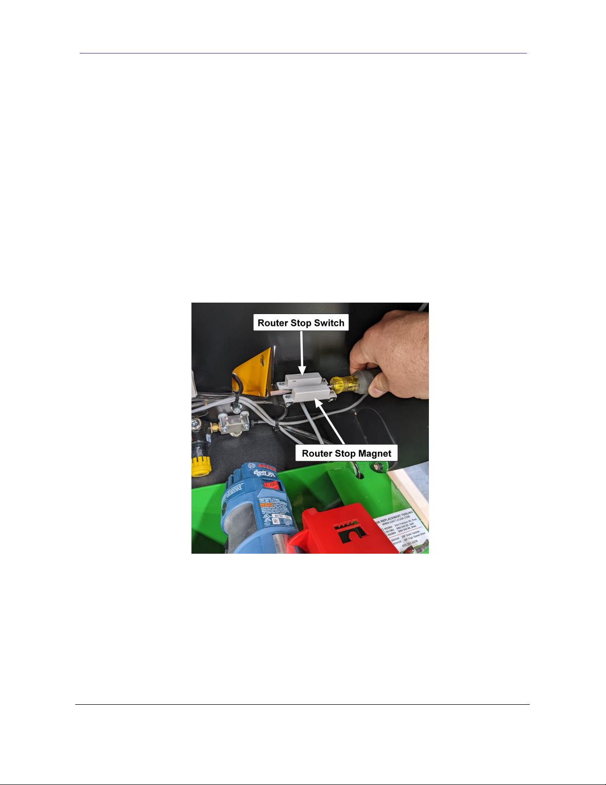
5.9ROUTER STOP SWITCH (NC) 21.22 ....................................................................................33
5.10 UNCLOGGING THE ROUTER SOLENOID 21.30 ........................................................................35
5.11ROUTER CHECK SOLENOID21.31.......................................................................................36
5.12ROUTER FEED RATE ADJUSTMENT 21.32 .............................................................................37
5.13DRILL MOTOR OPERATION 21.40 .......................................................................................38
5.14DRILL SETTINGS AND BIT DEPTH 21.41...............................................................................44
5.15DRILL SINGLE COIL BAR SPRING 21.42...............................................................................45
5.16DRILL STOP SWITCH (NC) 21.43 .......................................................................................47
5.17UNCLOGGING THE DRILL SOLENOID 21.50 ...........................................................................49
5.18DRILL SOLENOID CHECK 21.51..........................................................................................50
5.19DRIVE CYLINDER CHECK 21.60..........................................................................................52
2.3 Option #2 Dry Test TSM-22 With Work Top Open...................................................................8
5.2
MANUAL OVERRIDE ON SOLENOIDS 21.01.... ...................................................................20
CLAMP FOOT PAD OR CYLINDER REPLACEMENT 21.05 ...........................................................21

Castle Inc TSM-22 Diagnostic Manual V1 Page 3 of 74
5.21 PILOT HOLE ALIGNMENT 21.72 ...........................................................................................57
5.22FOOT SWITCH (NO) 21.80................................................................................................57
5.23RESETTING THE MACHINE 21.81........................................................................................59
5.24SAFETY SWITCH/SAFETY BUTTONS (NO) 21.82.....................................................................59
5.25TOOLING CHECK AND REPLACEMENT 21.83 .........................................................................61
5.26AIR PRESSURE REGULATOR SETTING 21.90 ........................................................................63
5.27REPLACING SOLENOID VALVES 21.91 .................................................................................64
5.28ATTACHING AIR SUPPLY 21.92 ..........................................................................................66
6APPENDIX A – MACHINE SAFETY 21.80.............................................................................67
6.1 GENERAL SAFETY RULES FOR MACHINE OPERATORS................................................................67
7APPENDIX B – WIRING DIAGRAM 21.84 ............................................................................69
8APPENDIX C – CONTROL BOX WORKS 21.93 ...................................................................70
9APPENDIX D – SOLENOID, PNEUMATIC DIAGRAM 21.94 ..................................................72
10APPENDIX E – INDEX .............................................................................................................73
5.20 EXHAUST MUFFLERS ON SOLENOID VALVES 21.65...........................................................55

Castle Inc TSM-22 Diagnostic Manual V1 Page 4 of 74
1Introduction
Thank you for making the Castle TSM-22 Screw Pocket Machine a vital part of your shop. The
TSM-22 is designed for use on a wide variety of materials including hardwoods, softwoods,
melamine, particleboard and MDF.
This manual is intended for anyone working with, or performing maintenance or service on the
TSM-22.
If trouble occurs, in most cases one of the major components is either not starting its function or
not completing its function. This may lead to a skip or stall in the operational sequence.
Troubleshooting the TSM-22 is greatly aided by understanding the machine’s
operational sequence which occurs in this order:
1. The Clamp extends to secure the work piece
2. The Router creates the pocket then retracts
3. The Drill creates the Pilot screw Hole then retracts
4. The Clamp releases the work piece

Castle Inc TSM-22 Diagnostic Manual V1 Page 5 of 74
1.1 How to Use This Manual
1. Closely observe the behavior of the machine noting which component is involved and
when in the operational sequence the problem is occurring.
2. Go to Section IV-Diagnostic Descriptions, which is organized by the operational
sequence of the machine.
3. Find the description which most closely matches the problem and systematically perform
the Diagnostic Procedures listed, checking them off as you go.
Example:
Page Procedure
Clamp comes down as soon as air is attached…with Machine power OFF:
.Check clamp Solenoid for function or blockage 12-13 21.11
Note: If you are unsure of your observations or if the fault behaviour seems irregular you
should “Dry Cycle” test the machine. See Procedure 21.95, page 6.

Castle Inc TSM-22 Diagnostic Manual V1 Page 6 of 74
2 Dry Cycle Testing 21.95
2.1 Purpose
Dry Cycle testing allows observation of the TSM-22’s mechanical, electrical, and
pneumatic functions without routing pockets or drilling holes.
Caution: Careful observation is essential when troubleshooting or seeking Technical Support
2.2 Dry Test TSM-22
1.
2. Connect air and power to the machine. Turn the machine’s MAIN Power Switch ON.
3. Depress one of the Safety Buttons with a piece of scrap wood positioned out of the path
of both the router and drill bits. Position yourself to see both the Router and Drill bits
when they extend.
4. Press the Foot Pedal and observe the following actions in this order.
1. The Clamp extends to secure the scrap wood
2. The Router extends then retracts
3. The Drill extends then retracts
4. The Clamp releases the scrap wood
Total elapsed time should be approximately two seconds.
5. If the cycle does not begin, check the Air Supply, the Foot Switch, and the Safety
Switch: Procedures 21.92, 21.80 and 21.82
6. If the cycle stalls with the router extended or if the cycle skips over the router stroke
entirely, check the Router Stop Switch: Procedure 21.22
Locate the ON/OFF switches on the Router and Drill and turn them both off.

Castle Inc TSM-22 Diagnostic Manual V1 Page 7 of 74
•
•
•If the Dry Cycle is successful, but a regular cycle fails when routing actual pockets
and drilling holes, check the Tooling, the Motor Operation, and the Drive Cylinder:
Procedures 21.83, 21.20 and 21.60
Note: For comprehensive diagnostic descriptions and procedures refer to Section IV.
If the cycle stalls with the drill extended or if the clamp starts to extend and then immediately retracts,
check the Drill Stop Switch: Procedure 21.43
If the complete cycle takes significantly longer than two seconds, check the Air
Supply, the Pressure Regulator, and the Router Feed Rate: Procedures 21.92, 21.90
and 21.32
After testing is complete, turn the MAIN Power Switch OFF and switch both motors back ON

2.3 Option #2 Dry Test TSM-22 With Work Top Open
1. Connect air and power to the machine. Turn the machine’s MAIN Power Switch ON.
2. Lift the work top of the machine.
3. Depress one of the Safety Buttons with a piece of scrap wood. Position yourself in front
of the machine.
4. Press the Foot Pedal and observe the following actions in this order.
1. The Clamp extends to secure the scrap wood
2. The Router extends then stops
3. Place a screw driver or a piece of metal in between the router stop switch and
the router stop magnetic. See Fig 1. The Drill should now extend and stop.
Fig 1
Castle Inc TSM-22 Diagnostic Manual V1 Page 8of 74
5. Place a screw driver or a piece of metal in between the drill stop switch and the drill
stop magnetic. See Fig 2.The drill should return to its resting position and the clamp should release.

6. If the cycle does not begin, check the Air Supply, the Foot Switch, and the Safety Switch: Procedures
21.92, 21.80 and 21.82
7. If the router stop switch can not be triggered with a screw driver or a piece of metal or if the cycle skips
over the router stroke entirely, check the Router Stop Switch: Procedure 21.22
•If the drill stop switch can not be triggered with a screw driver or a piece of metal or if the clamp
starts to come down and immediately retracts, check the Drill Stop Switch: Procedure 21.43
•If the Dry Cycle with the Work Top up is successful, but a regular cycle fails when routing actual
pockets and drilling holes, check the Tooling, the Motor Operation, and the Drive Cylinder:
Procedures 21.83, 21.20 and 21.60
Fig 2
Note: If a dry cycle is preformed to confirm function of the switches and the router bit or the
drill bit stays extended, verify that the carriage plate is not hitting the front of the switch/magnet.
The carriage plate should land in between the switch and the magnet.
Castle Inc TSM-22 Diagnostic Manual V1 Page 9of 74

Note: For comprehensive diagnostic descriptions and procedures refer to Section IV.
After testing is complete, turn the MAIN Power Switch OFF, then lower and secure the work top.
Note: A normal cycle when cutting pockets should take approximately 2
seconds. If the complete cycle takes significantly longer than two seconds,
check the Air Supply, the Pressure Regulator, and the Router Feed Rate:
Procedures 21.92, 21.90 and 21.32
Castle Inc TSM-22 Diagnostic Manual V1 Page 10 of 74

Castle Inc TSM-22 Diagnostic Manual V1 Page 11 of 74
3 Definitions
Term Definition
Air Pressure
Regulator
Used to set the main operational speed of the machine. Factory set at
approximately 75 PSI. / approximately 5 full clockwise turns from stop.
Bar Spring Provides pressure to return the Motor Carriage to neutral after the
Pilot Drill stroke.
Continuity Testing “Visual Indicator” type testers use batteries and a light
bulb.
“Audible Indicator” type testers use batteries and a
beeper or buzzer.
Normally OPEN (NO) switches read no continuity at rest, IE; NO light
or sound from tester.
Normally CLOSED (NC) switches read continuity at rest, IE: light or
sound from tester.
Drill Motor Bosch PR10E or PR20EVS Trimmer motor used to drill the Pilot Hole.
Drive Cylinder A double acting air cylinder which moves the Motor Carriage
backwards for the Pocket Router stroke and forwards for the Pilot Drill
stroke.
Pilot Hole The Screw hole drilled by the Drill motor.
Pocket The pocket cut in the material by the Pocket Router motor.
Router Motor Bosch 1617 or 1617EVS used to cut the Pocket.
Router Feed Rate
Valve
Controls the speed at which the Pocket Router moves through the
material when cutting the Pocket.
Note: Should be adjusted AFTER the main operational speed of
the machine has been set with the Air Pressure Regulator.

Castle Inc TSM-22 Diagnostic Manual V1 Page 12 of 74
Solenoids Electrically controlled air valves which send pressurized air to the
Clamp Cylinder and Drive Cylinder.
See Appendix C & E for illustrations.
Exhaust Muffler The exhaust mufflers on the solenoid valves release air pressure
from the clamping cylinder, and the drive cylinder after the Router
and Drill strokes.
Switches Normally OPEN (NO) switches at rest
Foot Switch
Safety Switch
Normally CLOSED (NC) switches
Router Stop Switch
Drill Stop Switch
Web The distance between the deepest part of the pocket and the edge of
the material.

Castle Inc TSM-22 Diagnostic Manual V1 Page 13of 74
4 Diagnostic Descriptions
4.1 Clamp Operation
Page Procedure
Clamp doesn’t come down, but Machine Routs and Drills:
□ Check Clamp cylinder air line for leakage………………………… 26 21.12
□ Check Clamp Solenoid for blockage.……………………………… 22 21.10
Clamp comes down and STAYS DOWN as soon as air is attached…with Machine power OFF:
□ Check Clamp Solenoid for function………………………………... 24 21.11
Clamp comes down, but immediately retracts…Machine does not Rout or Drill:
□ Check Drill Stop Switch……………………………………………... 47 21.43
Clamp doesn’t hold stock securely:
□ Clamp footpad replacement………………………………………… 20 21.05
□ Internal Air Pressure too low, adjust Pressure regulator………… 63 21.90
□ Router Feed Speed too fast, adjust Router Feed Rate………….. 3721.32
□61 21.83
□
Check Tooling, may be dull…………………………………………
Check Clamp Solenoid for blockage…………………….........….. 17-18 21.10
□ Check Clamp Cylinder for function.……………………………… 26 21.12
Clamp doesn’t come down, Machine Does NOT Rout or Drill:
□ Check Foot Switch………………………....................................… 57 21.80
□ Check Safety Switch (Stock Sense).……………………………… 59 21.82

Castle Inc TSM-22 Diagnostic Manual V1 Page 14 of 74
Page Procedure
Clamp releases slowly, Machine Routs and Drills:
□26 21.12
□21.13
Check Clamp cylinder and air line………………………………….
Check Exhaust Muffler on Clamp Solenoid Valve………....……. 27
Clamp doesn’t release…Machine Routs, and Drills:
□63 21.90
□
Adjust internal Air Pressure…………………………………………
Check Exhaust Muffler on Clamp Solenoid Valve……………….. 2721.13
□ Check Drill Stop Switch……………………………………………... 47 21.43
□
Check Exhaust Muffler on Router Solenoid Valve……………….. 55 21.65
□ Check Drill Solenoid for function or blockage…………………….. 50 21.51
□ Router Stop switch…………………………………………………... 33 21.22
Clamp doesn’t release…Machine Routs, DOES NOT Drill:
Clamp doesn’t release…Machine Routs but Router DOES NOT retract, DOES NOT Drill:
□ Check Drive Cylinder for function...................…………………….. 52 21.60
□□ Check Bar Spring position................................………………….. 45 21.42
□□ Check Bar Spring position................................…………………….. 45 21.42
□22 21.10 Check Clamp Solenoid for blockage.…………………………….

Castle Inc TSM-22 Diagnostic Manual V1 Page 15 of 74
4.2 Router Operation
Router doesn’t cut pocket… Machine Clamps, Drills and releases:
□ Check Router Stop Switch for function or adjustment…………… 33 21.22
Router comes up and STAYS UP as soon as air is attached…..with Machine power OFF:
□ Check Router Solenoid for function or blockage…………………. 3621.31
□ Unclog Router Solenoid…………………………………………….. 35 21.30
Router cuts pocket and STAYS UP, Drill doesn’t come out and Clamp doesn’t release:
□ Check Router Stop Switch for function or adjustment…………… 33 21.22
Router cuts pocket, Drill doesn’t come out and Clamp doesn’t release:
□49 21.50
□ Adjust internal Air Pressure………………………………………… 63 21.90
□ Adjust the Router Feed Rate……………………………………….. 3721.32
Check Drill Solenoid for function or blockage……………………..
□ .......…………………………………............. 21.60
□ …………………………………….21.65
52
55
Router advances too aggressively:
…………………………………….
□ Bar Spring Position........................………………............. 21.42
45

43-44 21.61
Router doesn’t cut pocket OR drill… Clamp doesn't release:
□37 21.32
Check Router Feed Rate (may be turned all the way down)….......
□ Check Router Solenoid for function or blockage……………....….…. 36 21.31
□ Drive Cylinder for leaks……………………………........…….. 52 21.60
□ for Blockage in Drill Solenoid Exhaust Muffler..…………….. 55 21.65
Castle Inc TSM-22 Diagnostic Manual V1 Page 16 of 74

Castle Inc TSM-22 Diagnostic Manual V1 Page 17 of 74
4.3 Drill Operation
Page Procedure
Drill DOES NOT come out, Machine Routs, Clamp DOES NOT release:
□ Check Drill Solenoid for function or blockage……………...……...21.51
□49 21.50
Drill comes out and stays out as soon as air is attached…with Machine power OFF:
□ 21.51
□ Adjust Air pressure, may be too low……………………………….. 63 21.90
□ Check Drill Solenoid for function or blockage …………………….. 50 21.51
□21.50
□
Check Router Solenoid Exhaust port for blockage………..……… 55 21.65
□ Check Drill Solenoid Exhaust port for blockage……………......…. 55 21.65
□ Adjust air pressure, Machine cycling too slowly………………….. 63 21.90
□ Bit mounted too deep into collet……………………………………. 44 21.41
Drill bit separating from the shank:
□ Adjust air pressure, Machine cycling too slowly………………….. 63 21.90
□ Bit mounted too deep into collet……………………………………. 44 21.41
Drill comes out and stops, Router cuts pocket and Clamp DOES NOT release:
Machine DOES finish cycle when carriage is pushed forward by hand:
Check Drill Solenoid for function / clean out drill solenoid...........
□21.50 □21.50 □
Unclog Drill Solenoid………………………………………………………………………………………………………………………………………………………………………………………………… 49 21.50
□□□□ Check drive cylinder for function.............................................…
Drill bit not completing pilot hole into Pocket:
52 21.60
□Check for inconsistent web depth-See Router Stop Switch......... 33 21.22
Unclog Drill Solenoid………………………………...............………
□
Check Bar Spring position.......................………........……………..21.42
□
Check Drill Stop Switch……………………………....................….. 47 21.43
□ Router Stop Switch...................................………….....…………..21.22
□Drill bit dull, Change drill bit......................................................... 61 21.83
33
45
50
50

Castle Inc TSM-22 Diagnostic Manual V1 Page 18 of 74
Page Procedure
Drill bit breaking:
□ Adjust air pressure, Machine cycling too fast ……………………... 63 21.90
□ Bit extended too far out of collet……………………………………. 44 21.41
□ Check Drill Motor U-bolt nuts……………………………………..… 39 21.40
4.4 Overall Machine Operation and Pocket Adjustment
Page Procedure
Machine will not start cycle…motors are running:
□ Check Air Supply, minimum 85 PSI required…………………….. 62 21.92
□
Check Safety Switch (Stock Sense)…………………………..…… 59 21.82
57 21.80 □ Check Foot Switch…………………………………………………..
Machine can be cycled with no stock in place:
□ Check the Safety Switch……………………………………………. 59 21.82
Machine cycling too slowly
Note: A normal cycle is approximately 2 seconds
□ Adjust Air Pressure Regulator……………………………………… 93 21.90
□ Check Drive cylinder for air leak…………………………………… 5221.60
□ Check for other air driven machines on the same line…………... 93 21.90
□ for Blockage in Drill Solenoid Exhaust Muffler..…...…….. 53 21.65
□ for Blockage in Router Solenoid Exhaust Muffler……..... 53 21.65

Castle Inc TSM-22 Diagnostic Manual V1 Page 19of 74
Page Procedure
Pocket ragged or crooked:
□ Adjust Router Feed Rate, may be too fast………………………... 3721.32
□ Check Clamp footpad, may need replacement…………………... 20 21.01
□ Check Tooling, may be dull………………………………………… 61 21.83
Pocket burned or smoking:
□ Adjust Router Feed Rate, may be too slow………………………. 3721.32
□ Check Tooling, may be dull………………………………………… 61 21.83
Pocket misaligned with pilot hole:
□ Adjust Pilot Hole alignment…………………………………………. 57 21.72
□ Check Drill motor mounting………………………………………… 39 21.40
Pocket too close or too far from the edge of the stock, WEB adjustment:
□ Adjust Web with Router Stop Plate………………………………... 32 21.21

5.1Manual Override on Solenoids 21.01
The solenoids can be manually overridden to allow air flow to the cylinder while air is
attached to the machine. This can also be used to flush air through the solenoid to remove
any moisture or debris. The manual override buttons are located on the end of the solenoids
opposite of the air ports. See Fig 4.
Fig 4
Castle Inc TSM-22 Diagnostic Manual V1 Page 20of 74
5.1.1 TO TEST SOLENOID FUNCTION AND FOR LEAKS:
1. Unplug the machine, but make sure air is attached.
2. Raise the work top up and locate the stack of solenoids on the left.
3. Depress the red button to allow air to flow through the solenoid to the cylinder to test for
function or listen for air leaks.
5.1.2 TO FLUSH THE SOLENOID:
1. Remove the air line out fitting and the exhaust muffler and press the override button for
several seconds. Air should flow through the solenoid. Reassemble and cut a test
pocket.
5 Procedures
Other manuals for TSM-22
2
Table of contents
Other CASTLE Cutter manuals