Struers Discotom-100 User manual

Discotom-100/-10
Instruction Manual
Manual No.: 16157001
Date of Release 06.03.2015

Discotom-100 /-10
Instruction Manual
Table of Contents Page
User’s Guide ............................................................... 1
Reference Guide ....................................................... 56
Quick Reference Guide ............................................ 88
Always state
Serial No and Voltage/frequency if you have technical questions or when ordering spare parts.
You will find the Serial No. and Voltage on the type plate of the machine itself. We may also need the
Date
and
Article No of the manual. This information is found on the front cover.
The following restrictions should be obser
ved, as violation of the restrictions may cause cancellation of
Struers legal obligations:
Instruction Manuals:
Struers Instruction Manuals may only be used in connection with Struers equipment
covered by the Instruction Manual.
Service Manuals:
Struers Se
rvice Manuals may only be used by a trained technician authorised by Struers.
The Service Manual may only be used in connection with Struers equipment covered by the Service Manual.
Struers assumes no responsibility for errors in the manual text/illustrations. The information in this manual is
subject to change without notice. The manual may mention accessories or parts not included in the present
version of the equipment.
Original instructions.
The contents of this manual are the property of Struers. Reproduction of any part of
this manual without the written permission of Struers is not allowed.
All rights reserved. © Struers
2015.
Struers A/S
Pederstrupvej 84
DK
-2750 Ballerup
Denmark
Telephone +45 44 600 800
Fax +45 44 600 801
FCC Notice
This equipment has been tested and found to comply with the limits for a
Class A digital device, pursuant to Part 15 of the FCC Rules. These limits
are designed to provide reasonable protection against harmful interference
when the equipment is operated in a commercial environment. This
equipment generates, uses, and can radiate radio frequency energy and, if
not installed and used in accordance with the Instruction Manual, may
cause harmful interference to radio communications. Operation of this
equipment in a residential area is likely to cause harmful interference in
which case the user will be required to correct the interference at his own
expense.
Pursuant to Part 15.21 of the FCC Rules, any changes or modifications to
this product not expressly approved by Struers A/S could cause harmful
radio interference and void the user’s authority to operate the equipment.

Discotom-100 /-10
Instruction Manual
Discotom-100 /-10
Safety Precaution Sheet
To be read carefully, before use
1. The operator(s) should be fully instructed in the use of the machine and
its cut-off wheels according to the Instruction Manual and the
instructions for the use of cut-off wheels.
2. The machine must be installed in compliance with local safety
regulations.
3. The machine must be placed on a safe and stable support table. All
safety functions and guards of the machine must be in working order.
4. Use only intact cut-off wheels. The cut-off wheels must be approved for
use with rotational speeds between 1500 and 3000 rpm.
5. The machine is not for use with saw-blade type cut-off wheels.
6. Observe the current safety regulations for handling, mixing, filling,
emptying and disposal of the additive for cooling fluid.
7. The workpiece must be securely fixed in the quick-clamping device or
similar. Large or sharp workpieces must be handled in a safe way.
8. Do not work on or around cutting table when the table is repositioned
using the Y-table positioning joystick.
9. To achieve maximum safety and lifetime of the machine, use only
original Struers consumables.
10. The cutting arm should be lowered slowly and carefully, in order to
avoid breaking the cut-off wheel.
11. Never look directly into the laser beam. (Line laser option)
12. Struers recommends the use of an exhaust system as the materials
being cut may emit harmful gasses or dust.
13. The machine emits only moderate noise. However, the cutting process
itself may emit noise, depending on the nature of the workpiece. In
such cases, the use of hearing protection is recommended.
14. The machine must be disconnected from the mains prior to any service.
15. Use of working gloves is recommended as workpieces may be both
very hot and produce sharp edges. Wearing of gloves is also
recommended when flushing and cleaning the machine.
16. Struers recommends the use of safety shoes when working with heavy
samples.

Discotom-100 /-10
Instruction Manual
17. Use of safety goggles is recommended when using the flushing hose.
18. If any of the cutting-chamber cover springs are damaged (at the rear of
machine), they must be replaced before the machine is used again.
19. When a recirculation cooling unit is used, observe the current safety
regulations for handling, mixing, filling, emptying and disposal of the
additive for cooling fluid.
Do not use flammable cooling fluid.
20. When lifting the machine using a forklift, lift from front or rear - never lift
the machine from the side.
21. When lifting the machine using lifting straps, ensure that the straps are
crossed and do not press on the sides of the machine.
1. Prior to any service, disconnect the machine then wait until residual
potential on the capacitors is discharged.
2. Do not cycle mains power more than once every three minutes.
Damage to the frequency converter will result.
Discotom-100
The equipment should only be used for its intended purpose and as detailed in the Instruction Manual.
The equipment is designed for use with consumables supplied by Struers. If subjected to misuse, improper
installation, alteration, neglect, accident or improper repair, Struers will accept no responsibility for
damage(s) to the user or the equipment.
Dismantling of any part of the equipment, during service or repair, should always be performed by a qualified
technician (electromechanical, electronic, mechanical, pneumatic, etc.)

Discotom-100 /-10
Instruction Manual
Disposal
Equipment marked with a WEEE symbol contain electrical and
electronic components and must not be disposed of as general
waste.
Please contact your local authorities for information on the correct
method of disposal in accordance with national legislation.


Discotom-100 /-10
Instruction Manual
1
User’s Guide
Table of Contents Page
1. Getting Started
Checking the Contents of the Packing Box ........................................ 3
Placing Discotom ............................................................................... 4
Lifting Instructions .............................................................................. 6
Getting Acquainted with Discotom ..................................................... 8
Two-handed Operation ........................................................... 10
Noise Level ...................................................................................... 10
Power Supply ................................................................................... 11
Connection to an External Exhaust System ..................................... 13
Connecting a Recirculation Cooling Unit .......................................... 14
2. Basic Operation
Using the Controls ............................................................................ 15
Front Panel Controls of Discotom ........................................... 15
Front Panel Controls ........................................................................ 16
Flush Hose ....................................................................................... 17
Moveable Table ................................................................................ 17
Y-Table ................................................................................... 17
Reading the Cutting Display ............................................................. 18
Reading the Display ................................................................ 19
Manoeuvring in the Menu Structure ........................................ 21
Acoustic Signals ...................................................................... 21
Software Settings ............................................................................. 22
Changing the Language .......................................................... 25
Editing Numeric Values ........................................................... 27
Editing Alphanumeric Values .................................................. 28
Operation Mode ............................................................................... 30
Changing Operation Mode ...................................................... 30
New Pass Code ............................................................................... 31
Changing Cutting Mode and Cutting Parameters............................. 32
Changing Cutting Mode .......................................................... 32
Changing Cutting Parameters ................................................. 33
Selecting a Cut-off Wheel ....................................................... 33
Changing the Wheel Speed .................................................... 38
Selecting the Cutting Mode ..................................................... 39
Stop Modes ...................................................................................... 44
Auto ......................................................................................... 44
Relative Stop Position ............................................................. 46
Absolute Stop Position ............................................................ 47
Using Motor Load and Temperature Display .......................... 48
OptiFeed ................................................................................. 48

Discotom-100 /-10
Instruction Manual
2
Fitting or Changing the Cut-off Wheel .............................................. 49
Clamping the Workpiece .................................................................. 49
Positioning the Cutting Table ........................................................... 49
Starting/Stopping the Cutting Process ............................................. 50
Automatic Cutting .................................................................... 50
Manual Cutting ........................................................................ 51
Combining Manual and Automatic Operation ........................ 51
3. Routine Maintenance
AxioWash ......................................................................................... 52
Daily Service .................................................................................... 53
Cleaning of Flush Hose Nozzle ........................................................ 53
Weekly Maintenance ........................................................................ 54
Monthly Maintenance ....................................................................... 54
Replacing the Cooling Water .................................................. 54
Lubricating the Cutting Table .................................................. 54
Yearly Service .................................................................................. 55
Inspection of Cover ................................................................. 55

Discotom-100 /-10
Instruction Manual
3
1. Getting Started
In the packing box you should find the following parts:
1 Fork spanner (24 mm) for cut-off wheel
1 Triangle key for safety lock release
1 Connector pipe for water outlet
1 Elbow pipe for water outlet
1 Outlet hose 2 m,
for connection to external cooling unit
1 Hose clamp, 70-90 mm
1 Instruction Manual set
Remove the bolts from all of the transport brackets that secure
the Discotom to its transport pallet.
Remove the brackets.
Checking the Contents
of the Packing Box
Unpacking Discotom
Discotom-100 /-10
Instruction Manual
4
Discotom should be placed on a table strong enough to support a
minimum of 200 kg/ 440 lbs.
Struers recommends the use of the Table Unit, which is designed for
use with Discotom machines, see “Accessories”.
Discotom-100/-10 is recommended to be placed on a table unit (with
a compartment for recirculation cooling unit) with the dimensions:
Width: 920 mm / 36.2”
Depth: 900 mm / 35.4”
Height: 800 mm / 31.5”
(A table unit designed for Struers’ table top cut-off machines is
available as an accessory Cat. No. 06266101)
Make sure there is enough room behind the table for the inlet and
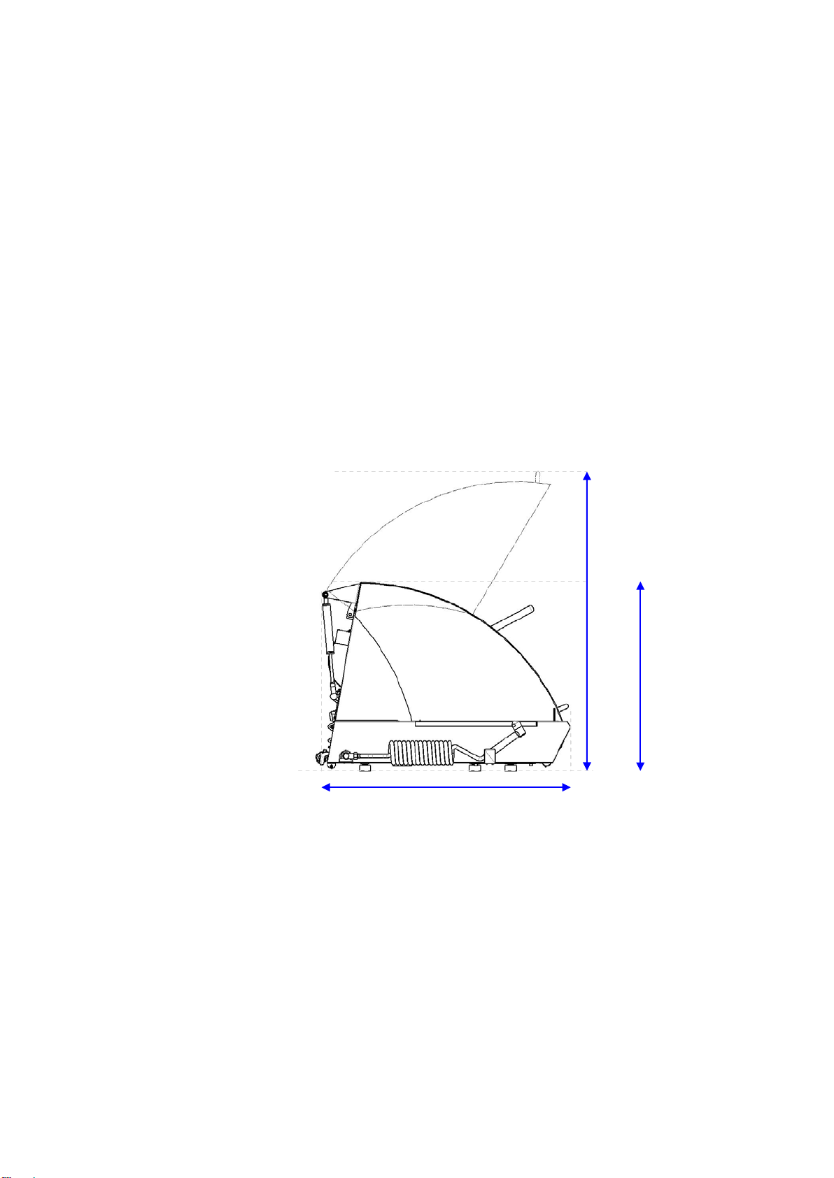
outlet hoses and for the cover to be opened fully (see illustration).
Placing Discotom
Space required
890 mm / 35”
685 mm / 27”
1080mm mm / 42.5”

Discotom-100 /-10
Instruction Manual
5
Discotom-100/-10 may be placed against a wall.
If an external exhaust system is connected to the unit via the fitting
on the rear, ca 17 cm / 7” of space is required for the hose.
Recommended space at the front: 100 cm / 40”.
The recirculation cooling unit can be placed in the table unit
compartment and does not require extra space.
Footprint:
97.7 cm / 38.55”
89 cm / 35”

Discotom-100 /-10
Instruction Manual
6
A crane and 2 lifting straps are required to lift Discotom-10/-100 off
the shipment pallet.
Before lifting Discotom into position:
Carefully open and remove the sides and the top of the packing
crate.
Remove the brackets securing Discotom to the pallet (a torque
bit T30 key is required to remove the coach bolts that secure the
transport brackets).
Place the two lifting straps under Discotom.
− Position the straps under Discotom, so that they are on the
outer side of the feet/ rollers.
− Use straps which are long enough so that they do not place
stress on the glass window (use straps of approx. 3-3½ m in
length).
A lifting bar is recommended so that the two straps are kept
apart below the lifting point.
Lifting Instructions
With a crane
Position straps here
Position straps here
With lifting bar
Without lifting bar

Discotom-100 /-10
Instruction Manual
7
Lift Discotom onto the table.
Lift the front of Discotom and carefully move into place using the
rollers.
A forklift truck can be used to lift Discotom off the shipment pallet.
Before lifting Discotom into position:
Carefully open and remove the sides and the top of the packing
crate.
Remove the brackets securing Discotom to the pallet (a torque
bit T30 key is required to remove the coach bolts that secure the
transport brackets).Lift Discotom from the pallet using a forklift
truck.
Position the forks so that the centre of mass is between the forks
– see illustrations.
Lift Discotom onto the table.
Lift the front of Discotom and carefully move into place using the
rollers.
With a Fork lift

Discotom-100 /-10
Instruction Manual
8
Take a moment to familiarise yourself with the location and names of
the Discotom’s components.
Control panel
Cutting arm
Turn /Push Knob
Joystick for table movement
Flushing gun
Two-hand operation button
Access hole for safety lock release
Getting Acquainted
with Discotom
Front View
Note!
The cover on Discotom can only be opened when the machine is connected
to a power supply and the main power switch is on.
To open the cover when the power is not connected, insert the triangle key
through the access hole at the front to release the safety lock.
Remember to re-activate the safety lock release
before operating Discotom.

Discotom-100 /-10
Instruction Manual
9
Emergency stop
Main power switch
The main switch is located on the right hand side of Discotom.
Turn clockwise to switch on the power.
Cooli unit connection
Service socket (RS232)
Power supply cable connection
Water inlet
Water outlet flange
Flushing hose
Exhaust connection
Side view, right
Rear View

Discotom-100 /-10
Instruction Manual
10
When moving the cut-off wheel whilst the cover is open, the button
on the front of Discotom must be pressed and held just before the
joystick is operated.
Approx. 67 dB (A) measured at idle running, at a distance of
1.0 m/39.4” from the machine.
Two-handed Operation
Noise Level
Press and hold the button,
then move the joystick.

Discotom-100 /-10
Instruction Manual
11
Open the electric connection box and connect a 4-lead or 5-lead
cable* in the following way:
PE: earth
N: neutral (not used)
L1: phase
L2: phase
L3: phase
EU cable UL cable
L1 Brown
L2 Black
L3 Black or grey
Earth Yellow/ green
Neutral Blue (Not used)
L1 Black
L2 Red
L3 Orange/ turquoise
Earth Green (or Yellow/ green)
Neutral White (Not used)
The other end of the cable can be fitted with an approved plug or
hard-wired into the mains, according to the electrical
specifications and local regulations.
*Please see the section on Technical Data at the rear of the
Instruction Manual for recommended cable specifications.
Power Supply
IMPORTANT
Check that the mains voltage corresponds to the voltage stated on the type
plate on the side of the machine.
Discotom-100 / -10

Discotom-100 /-10
Instruction Manual
12
Check that the cut-off wheel rotates in the direction indicated by
the arrow on the cut-off wheel guard. If the direction of rotation is
incorrect:
EU cable UL cable
Switch two of the phases Switch phases L1 and L2
Both requirements refer to the European standard EN 50178 /
5.2.11.1. Similar standards apply in North America.
Direction of the Cut-off Wheel
(Discotom-10 only)
Important:
For Electrical Installations with Residual Current Circuit Breakers
For Discotom-100 connected to electrical installations with residual current
circuit breakers, a residual current circuit breaker,
type B time delayed, 30 mA is REQUIRED
(ref. EN 50178 / 5.2.11.1).
For Electrical Installations without Residual Current Circuit Breakers
The equipment must be protected by an insulation transformer
(double-wound transformer)
Please contact a qualified electrician to verify which option is suitable for the
local installation setup.

Discotom-100 /-10
Instruction Manual
13
Struers recommends the use of an exhaust system, as workpieces
may emit harmful gases when cut. The exhaust system will also
reduce the level of water condensation on the sides of the cover.
To connect the Discotom to an exhaust system:
Mount an exhaust hose from your local exhaust system onto the
flange (50 mm (approx. 2") dia.).
Connection to an External
Exhaust System
Important
If no exhaust is connected, damp air (produced by the cutting process) may
escape from the cutting chamber and penetrate into other areas of the
cabinet. This may cause damage to components and shorten the lifetime of
the machine.
Exhaust connection

Discotom-100 /-10
Instruction Manual
14
To ensure optimal cooling, Discotom must be fitted with a
recirculation cooling unit. Cooling System 4 is a configuration
designed for use with Discotom.
To connect the Discotom to a Recirculation Cooling Unit:
Plug the Cooli control unit’s communication cable into the
Discotom’s control socket.
Connect the water inlet hose to the Cooli pump using the quick
coupling (A).
Connect the other end of the hose to the Discotom water inlet.
Mount the 90° elbow pipe on the straight connector pipe in
the water outlet on the back of Discotom. Lubricate the sealing
ring with grease or soap to facilitate insertion.
Mount the outlet hose onto the elbow pipe and clamp using a
hose clamp.
Check that the outlet hose slopes downwards when connected. If
necessary adjust the length of the hose.
Insert the other end of the hose into the mounting hole in the
bracket on top of the Cooli filter unit (B).
Connect the cooling unit to the mains power supply.
Connecting a Recirculation
Cooling Unit
Note:
Cooling System 4 includes a static filter.
For intensive use, and for materials generating a lot of swarf,
a bandfilter such as Coolimat-200 is recommended.
Note
Before connecting the cooling unit to the Discotom,
follow the instructions in the Cooling Units Instruction Manual
to prepare it for use.
IMPORTANT
Before connecting, check that the mains voltage corresponds to the voltage
stated on the type plate on the side of the machine.
A
B
Other manuals for Discotom-100
1
This manual suits for next models
1
Table of contents
Other Struers Cutter manuals


