Catalyst 77722-00 User manual

OPERATING MANUAL:
FH100 PRECISION
VARIABLE-SPEED
PERISTALTIC PUMP
SYSTEM
Model 77722-00
Model Nos.
77722-00
77722-02
A-1299-7292
Edition 01
(US & Canada only) Toll Free 1-800-MASTERFLEX • 1-800-637-3739
(Outside US & Canada) 1-847-549-7600 • 1-847-381-7050
E-mail: techinf[email protected]
www.masterflex.com • www.coleparmer.com

Cole-Parmer
Preface
FH100 Precision Variable-Speed Peristaltic Pump System Operating Manual ii
Preface
© 2014 Cole-Parmer Instrument Company LLC. All rights reserved.
NORPRENE, PHARMED and TYGON – Reg TM Saint-Gobain Performance Plastics Corp.
Trademarks bearing the ®symbol in this publication are registered in the U.S. and in other countries.
A-1299-7292
01 19714 2014-10-29 First Edition SR
REV ECR/ECN DATE DESCRIPTION By

DANGER: Remove power from the pump before any
cleaning operation is started.
WARNING: Remove power from the pump before attempting
any maintenance.
WARNINGS: Tubing breakage may result in fluid being sprayed
from pump. Use appropriate measures to protect operator and
equipment.
Turn Pump System off before removing or installing tubing.
Fingers or loose clothing could get caught in drive mechanism.
CAUTIONS: When changing flow direction, allow the pump to
come to a complete stop before starting again. Failure to do so
could cause permanent damage to the motor.
Replace the fuse only with one of the same type and rating.
The fuse rating and type are stated on the rear panel.
CAUTION: To avoid electrical shock, the power cord
protective grounding conductor must be connected to ground.
Not for operation in wet locations as defined by EN61010-1.
If the product is not used in a manner specified in the
instructions, the protection provided by the equipment may
be impaired.
CAUTION: Risk of Danger. Consult Operator’s manual for nature
of hazard and corrective actions.
CAUTION: Risk of crushing. Keep fingers away from rotor
while pump is in operation. Stop pump before loading or
unloading tubing.
CAUTION: Hot Surface. Do not touch.
CAUTION: Risk of electric shock. Consult Operator’s manual
for nature of hazard and corrective actions.
This product is not designed for, nor intended for use in patient
connected applications; including, but not limited to, medical
and dental use, and accordingly has not been
submitted for FDA approval.
This product is not designed for, nor intended for use in
hazardous duty areas as defined by ATEX or the NEC (National
Electrical Code); including, but not limited to use with
flammable liquids. Consult the factory for products suitable
for these types of applications.
Cole-Parmer FH100 Precision Variable-Speed Peristaltic Pump System Operating Manual iii
Preface
Safety Precautions
SAFETY
PRECAUTIONS
Explanation of
Symbols
WARNING:
Product Use
Limitation

1. Read instructions before operating the unit.
2. Observe safety precautions at all times, especially when pumping
dangerous liquids. Always have the clear plastic cover properly
mounted on the Pump Head and, in general, protect the pump area
from accidental spillage of liquid.
3. If the pump runs unusually noisily or if bunching of the tubing in the
pump can be observed, make sure the tubing is clamped down tightly
and/or replace it with a new piece of tubing.
4. The FH100 Pump System must be well-grounded at all times.
5. The FH100 Pump System is equipped with a current-limiting circuit
that will slow the motor down if any of the following conditions exist:
a. Tubing that is too hard is loaded in the pump.
b. Incorrect tubing size or wall thickness is loaded in the pump.
c. Tubing is improperly loaded into the Pump Head.
6. The unit is fused and grounded to protect the operator in the event of
short circuits that could be caused by liquid entering the case.
CAUTION: Replace the fuse only with one of the same type
and rating. The fuse rating and type are stated on the
rear panel.
7. The Pump System should not be used in outdoor or hazardous
locations.
Safety
Cole-Parmeriv FH100 Precision Variable-Speed Peristaltic Pump System Operating Manual
Preface

FH100 Precision Variable-Speed Peristaltic Pump System Operating Manual vCole-Parmer
Table of Contents
Page
INTRODUCTION . . . . . . . . . . . . . . . . . . . . . . . . . . . . . . . . . . . . . . . . . . . . . .1-1
General Description . . . . . . . . . . . . . . . . . . . . . . . . . . . . . . . . . . . . . . . . . . . . .1-1
Controls, Indicators and Connectors . . . . . . . . . . . . . . . . . . . . . . . . . . . . . . . .1-2
INSTALLATION AND SETUP . . . . . . . . . . . . . . . . . . . . . . . . . . . . . . . . . . .2-1
Tubing Size Selection . . . . . . . . . . . . . . . . . . . . . . . . . . . . . . . . . . . . . . . . . . .2-1
OPERATION . . . . . . . . . . . . . . . . . . . . . . . . . . . . . . . . . . . . . . . . . . . . . . . . .3-1
Inserting Tubing . . . . . . . . . . . . . . . . . . . . . . . . . . . . . . . . . . . . . . . . . . . . . . . .3-1
Tubing Inspection and Replacement . . . . . . . . . . . . . . . . . . . . . . . . . . . . . . .3-2
Pump Controls . . . . . . . . . . . . . . . . . . . . . . . . . . . . . . . . . . . . . . . . . . . . . . . .3-2
External Operation . . . . . . . . . . . . . . . . . . . . . . . . . . . . . . . . . . . . . . . . . . . . . .3-3
External Inputs . . . . . . . . . . . . . . . . . . . . . . . . . . . . . . . . . . . . . . . . . . . . . . . . .3-4
MAINTENANCE . . . . . . . . . . . . . . . . . . . . . . . . . . . . . . . . . . . . . . . . . . . . . .4-1
Cleaning . . . . . . . . . . . . . . . . . . . . . . . . . . . . . . . . . . . . . . . . . . . . . . . . . . . . . .4-1
TROUBLESHOOTING . . . . . . . . . . . . . . . . . . . . . . . . . . . . . . . . . . . . . . . . . .5-1
Troubleshooting Chart . . . . . . . . . . . . . . . . . . . . . . . . . . . . . . . . . . . . . . . . . . .5-1
REPLACEMENT PARTS and ACCESSORIES . . . . . . . . . . . . . . . . . . . . . .6-1
Replacement Parts . . . . . . . . . . . . . . . . . . . . . . . . . . . . . . . . . . . . . . . . . . . . .6-1
Accessories . . . . . . . . . . . . . . . . . . . . . . . . . . . . . . . . . . . . . . . . . . . . . . . . . . .6-1
SPECIFICATIONS . . . . . . . . . . . . . . . . . . . . . . . . . . . . . . . . . . . . . . . . . . . . .7-1
WARRANTY, PRODUCT RETURN and TECHNICAL ASSISTANCE . . . .8-1
Warranty . . . . . . . . . . . . . . . . . . . . . . . . . . . . . . . . . . . . . . . . . . . . . . . . . . . . .8-1
Product Return . . . . . . . . . . . . . . . . . . . . . . . . . . . . . . . . . . . . . . . . . . . . . . . . .8-2
Technical Assistance . . . . . . . . . . . . . . . . . . . . . . . . . . . . . . . . . . . . . . . . . . . .8-2
Section 1
Section 2
Section 3
Section 6
Section 8
Section 7
Section 4
Section 5


Figures
Page
Controls, Indicators and Connectors . . . . . . . . . . . . . . . . . . . . . . . . . . . . . . . .1-2
Tube Loading Upper Retainer . . . . . . . . . . . . . . . . . . . . . . . . . . . . . . . . . . . . .3-1
Tube Loading Lower Retainer . . . . . . . . . . . . . . . . . . . . . . . . . . . . . . . . . . . . .3-2
DB9 Pin Configuration with Wiring Scheme . . . . . . . . . . . . . . . . . . . . . . . . .3-3
FH100 Precision Variable-Speed Peristaltic Pump System Operating Manual viiCole-Parmer
Figures


FH100 Precision Variable-Speed Peristaltic Pump System Operating Manual 1-1Cole-Parmer
Section 1 Introduction
The FH100 Precision Variable-Speed Peristaltic Pump System provides
continuous pumping of fluids while power is supplied.
These Pump Systems are ETL and CE certified. The pump speed range
for both models is 4-400 rpm.
General Description
1-2 FH100 Precision Variable-Speed Peristaltic Pump System Operating Manual Cole-Parmer
Section 1
Introduction
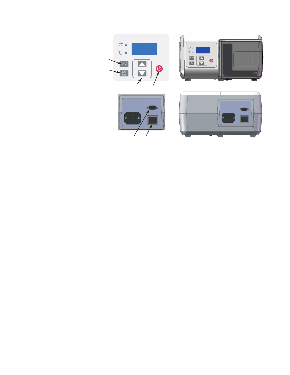
Controls, Indicators
and Connectors
Rear View
Figure 1-1. Controls, Indicators and Connectors
A
BE
C
D
A. POWER (ON/OFF) SWITCH: Turns the unit ON or OFF.
B. SPEED KEYS: Sets the speed of the pump. The higher the number,
the faster the speed of the pump. When setting the displayed values,
units change first, then tens, etc. at an increasing rate.
C. FLOW DIRECTION KEY: Sets the direction of the rotation of the
pump Clockwise/Counterclockwise. An LED annunciator shows the
active direction. The motor is brought to a controlled stop before
reversing direction.
D. INTERNAL/EXTERNAL KEY: This key changes the mode of
operation for the drive. Internal (Local) operation throught the front
panel keypad is designated by “INT” while external (Remote)
operation is designated by “EXT”. In INT mode, START/STOP,
FLOW DIRECTION, and SPEED keys on the front panel
determine operating state. Pressing and releasing this key will toggle
between the two operating states.
E. START/STOP KEY: When depressed, this key toggles the motor on
and off when in INT mode. This key will not normally start the drive
if in EXT mode. If pressed while running in EXT mode (stop
desired), the button will always stop the drive and a toggle of the
EXT Start/Stop is required to restart the drive.
F. EXTERNAL/REMOTE CONNECTOR: Used to connect wiring for
remote control operation using a DB9 connector.
F
Front View
This manual suits for next models
1
Table of contents
Popular Water Pump manuals by other brands


DUROMAX
DUROMAX XP WX Series user manual

BRINKMANN PUMPS
BRINKMANN PUMPS SBF550 operating instructions

Franklin Electric
Franklin Electric IPS Installation & operation manual

Xylem
Xylem e-1532 Series instruction manual

Milton Roy
Milton Roy PRIMEROYAL instruction manual

STA-RITE
STA-RITE ST33APP owner's manual