Yard force LX CAP1 User manual

1
20V AIR PUMP
Original Instructions
GB
LX CAP1
TB-HT09-20
READ & UNDERSTAND INSTRUCTION MANUAL
Save all warnings and instructions for future reference.

2 3
A
B
11 1
2
12
15 14 13
3
12
9
8
7
6
5
4
c
g
h
e
f
d
b
a

4 5
C K
E
G
F
H
D
I J
1
3
2
%

6 7
LX CAP1 Original Instructions
CONTENT
INTENDED USE
This air pump is intended for inating car and bicycle tyres, sports/gym balls and
the like. It is designed for domestic use and is not designed for commercial, trade
or industrial use.
GENERAL POWER TOOL SAFETY WARNINGS
WARNING! Read all safety warnings and all
instructions. Failure to following the warnings
and instructions may result in an electric shock,
re and/or serious injury.
Save all warnings and instructions for future
reference!
The term “power tool” in the warnings refers to your
mains-operated (corded) power tool or battery-operated
(cordless) power tool.
Work area safety
1. Keep work area clean and well lit. Cluttered or dark
areas invite accidents.
2. Do not operate power tools in explosive
atmospheres, such as in the presence of
ammable liquids, gases or dust. Power tools
create sparks which may ignite the dust of fumes.
3. Keep children and bystanders away while
operating a power tool. Distractions can cause you
to lose control.
Electrical safety
1. Power tool plugs must match the outlet. Never
modify the plug in any way. Do not use any
adapter plugs with earthed (grounded) power
Intended use 07
General safety warnings 07
Product safety warnings 10
Symbols 13
Technical data 16
Description of product 17
Operation 18
Maintenance and storage 21
Troubleshooting 21
CE declaration 22

8 9
tools. Unmodied plugs and matching outlets will
reduce the risk of electric shock.
2. Avoid body contact with earthed or grounded
surfaces, such as pipes, radiators, ranges and
refrigerators. There is an increased risk of electric
shock if your body is earthed or grounded.
3. Do not expose power tools to rain or wet
conditions. Water entering a power tool will increase
the risk of electric shock.
4. Do not abuse the cord. Never use the cord for
carrying, pulling or unplugging the power tool.
Keep cord away from heat, oil, sharp edges or
moving parts. Damaged or entangled cords increase
the risk of electric shock.
5. When operating a power tool outdoors, use an
extension cord suitable for outdoor use. Use of
a cord suitable for outdoor use reduces the risk of
electric shock.
6. If operating a power tool in a damp location is
unavoidable, use a residual current device (RCD)
protected supply. Use of an RCD reduces the risk of
electric shock.
Personal safety
1. Stay alert, watch what you are doing and use
common sense when operating a power tool.
Do not use a power tool while you are tired or
under inuence of drugs, alcohol or medication.
GENERAL POWER TOOL SAFETY WARNINGS
A moment of inattention while operating power tools
may result in serious personal injury.
2. Use personal protective equipment. Always wear
eye protection. Protective equipment such as dust
mask, non-skid safety shoes, hard hat, or hearing
protection used for appropriate conditions will reduce
personal injuries.
3. Prevent unintentional starting. Ensure the switch
is in the off-position before connecting to power
source and/or battery pack, picking up or carrying
the tool. Carrying power tools with your nger on the
switch or energising power tools that have the switch
on invites accidents.
4. Remove any adjusting key or wrench before
turning the power tool on. A wrench or a key left
attached to a rotating part of the power tool may
result in personal injury.
5. Do not overreach. Keep proper footing and
balance at all times. This enables better control of
the power tool in unexpected situations.
6. Dress properly. Do not wear loose clothing or
jewellery. Keep your hair, clothing and gloves
away from moving parts. Loose clothes, jewellery or
long hair can be caught in moving parts.
7. If devices are provided for the connection of dust
extraction and collection facilities, ensure these
are connected and properly used. Use of dust
collection can reduce dust-related hazards.
GENERAL POWER TOOL SAFETY WARNINGS

10 11
PRODUCT SAFETY WARNINGS
Power tool use and care
1. Do not force the power tool. Use the correct
power tool for your application. The correct power
tool will do the job better and safer at the rate for
which it was designed.
2. Do not use the power tool if the switch does not
turn it on and off. Any power tool that cannot be
controlled with the switch is dangerous and must be
repaired.
3. Disconnect the plug from the power source and/
or the battery pack from the power tool before
making any adjustments, changing accessories,
or storing power tools. Such preventive safety
measures reduce the risk of starting the power tool
accidentally.
4. Store idle power tools out of reach of children and
do not allow persons unfamiliar with the power
tool or these instructions to operate the power
tool. Power tools are dangerous in the hands of
untrained users.
5. Maintain power tools. Check for misalignment or
binding of moving parts, breakage of parts and
any other condition that may affect the power
tool's operation. If damaged, have the power tool
repaired before use. Many accidents are caused by
poorly maintained power tools.
6. Keep cutting tools sharp and clean. Properly
maintained cutting tools with sharp cutting edges are
less likely to bind and are easier to control.
PRODUCT SAFETY WARNINGS
7. Use the power tool, accessories and tool bits
etc. in accordance with these instructions,
taking into account the working conditions and
the work to be performed. Use the power tool for
operations different from those intended could result
in hazardous situations.
Battery tool use and care
1. Recharge only with the charger specied by the
manufacturer. A charger that is suitable for one type
of battery pack may create a risk of re when used
with another battery pack.
2. Use power tools only with specically designated
battery packs. Use of any other battery packs may
create a risk of injury and re.
3. When battery pack is not in use, keep it away from
other metal objects, like paper clips, coins, keys,
nails, screws or other small metal objects, that can
make a connection from one terminal to another.
Shorting the battery terminals together may cause
burns or a re.
4. Under abusive conditions, liquid may be ejected
from the battery; avoid contact. If contact
accidentally occurs, ush with water. If liquid
contacts eyes, additionally seek medical help.
Liquid ejected from the battery may cause irritation or
burns.

12 13
PRODUCT SAFETY WARNINGS
Service
Have your power tool serviced by a qualied repair
person using only identical replacement parts. This
will ensure that the safety of the power tool is maintained.
Special safety notes for air pump
• Observe the maximum pressure. Do not inate any
items to excess pressure.
• The air pump is designed for occasional use. Allow the
air pump to cool down after 5 minutes of use.
• Never use the air pump near ammable uids or
gases.
• Never allow anyone to pump air into mouth, ears, nose
etc. of people and animals.
• Do not direct air stream at body.
• Do not expose to rain.
Residual risk
Even if you use the air pump as prescribed, it is not
possible to eliminate all residual risk. The following
hazards may arise:
• Damage to the lungs if an effective breathing mask is
not worn.
• Damage to hearing if effective ear protection is not
worn.
• Damage to the eyes if effective eye protection is not
worn.
SYMBOLS
Safety symbols
The purpose of safety symbols is to attract your
attention to any possible dangers. The safety symbols
and their explanations deserve your careful attention
and full understanding. The symbol warnings do not, by
themselves, eliminate any danger. The instructions and
warnings they give are no substitute for proper accident
prevention measures.
WARNING: Be sure to read and understand
all safety instructions within this operator’s
manual, including all safety alert symbols such as
“DANGER”, “WARNING”, and “CAUTION” before
using this tool. Failure to follow all instructions
listed below may result in electric shock, re and/or
serious personal injury.
SAFETY ALERT SYMBOLS: Indicate DANGER,
WARNING, or CAUTION. May be used in conjunction
with other symbols or pictographs.
Symbol meanings
This page depicts and describes safety symbols that
may appear on this product. Read, fully understand and
follow all instructions on the machine before attempting
to assemble and operate.

14 15
Batteries contain Li-ion. Do not dispose of
waste batteries in domestic waste. Contact local
authority to nd out how to dispose of batteries.
WEEE symbol. Waste electrical products should
not be disposed of with household waste. Please
recycle where facilities exist. Check with your
Local Authority or local store for recycling advice.
Warning symbols on the charger
To reduce the risk of injury, user must read the
instruction manual carefully.
The charger is for indoor use only.
Double insulation
WEEE symbol. Waste electrical products should
not be disposed of with household waste. Please
recycle where facilities exist. Check with your
Local Authority or local store for recycling advice.
The product complies with the applicable
European directives and an evaluation method of
conformity for these directives was done.
Protective 3.15 A limited
SYMBOLS SYMBOLS
Denotes risk of personal injury or damage to the
tool
Read instruction manual before use
Dispose appliances according to the regulation
and requirement of local council
The product complies with the applicable
European directives and an evaluation method of
conformity for these directives was done.
Warning symbols on the battery pack
To reduce the risk of injury, user must read the
instruction manual carefully.
Do not throw into water.
Do not throw to re.
Do not subject the battery to strong sunlight over
long periods of time. Do not leave on a heater
(max.45°C). T3.15A

16 17
Parts description (Fig. A)
1. Air Chuck
2. Adapter Storage Area
3. Battery (not included)
4. Ball Needle Adapter
5. Tapered Universal Adapter
6. Trigger Switch
7. LED Worklight
8. Air Hose Connector
9. Air Hose Storage Area
10. Air Hose
11. Air Chuck Clamp
12. Digital Pressure Gauge
13. Pressure Setting (-)
14. Pressure Setting (+)
15. Power and Mode Button
PACKAGE CONTENT LIST (Fig. B)
Remove the machine from its packaging carefully and make sure that all of the following parts
are present:
a. Air Pump
b. Air hose with Air Chuck
c. Tapered Universal Adapter
d. Ball Needle Adapter
e. Instruction Manual
f. Battery pack
g. Charger
h. Presta valve adapter
WARNING: If any parts are damaged or missing, do not operate this tool until these
parts have been replaced. Failure to heed this warning could result in serious
personal injury.
NOTE: Always recycle the packaging in accordance with local recycling guidelines.
PARTS DESCRIPTION
TECHNICAL DATA
Model No. LX CAP1
Rated voltage 20V
Maximum pressure 8.27 bar/120 PSI
Maximum operating time 5 min
Weight 0.8 kg
Product dimension 21.5cm X 15cm X 7.5cm
Battery pack model B0P-SP07-20ZN
Capacity 20 V , 2.0 Ah
Charger model VDE: B0Q-SP06-20ZA
Input 220–240 V AC, 50/60 Hz, 65W
Output: 20 V , 2.4 A
Protection class II

18 19
OPERATIONOPERATION
WARNING: Always observe the pressure on the pressure gauge. Never inflate
object to a pressure greater than the maximum pressure specified by the
manufacturer of the object.
WARNING: Switch off the air pump immediately should any danger arise.
WARNING: The metal parts on the adaptor and air hose can become very hot.
Allow the parts to cool down before touching these parts.
WARNING: The air pump should not continue operating for more than 5
minutes. After 5 minutes, it must be switched off and allowed to cool down
for at least 10 minutes before restarting.
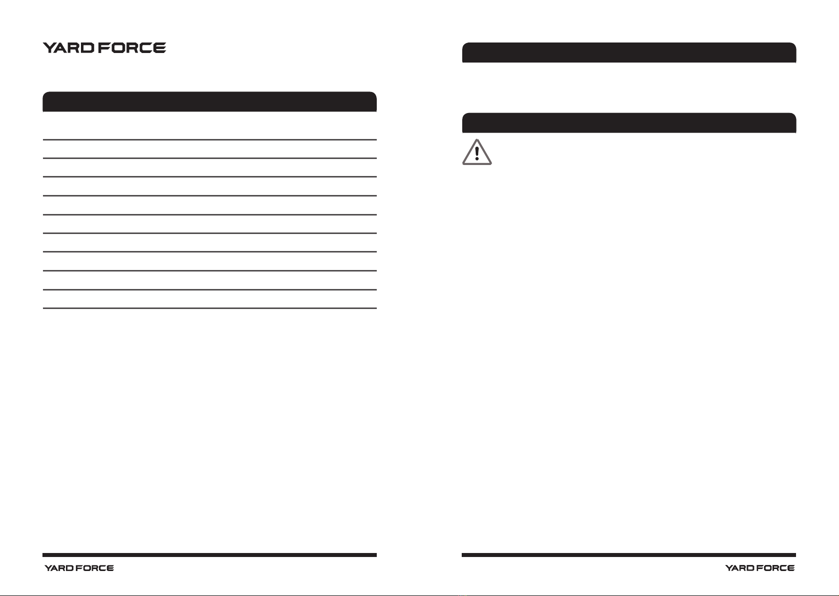
Insert and remove the battery pack
WARNING: Before inserting or removing the battery pack, make sure the air
pump is switched off.
1. To insert the battery pack, align the battery pack with the air pump's base and slide the
battery pack into the air pump, so that the battery pack is locked in position. (Fig. E)
2. To remove the battery pack, press the battery’s release button and pull the battery pack
off at the same time. (Fig. F)
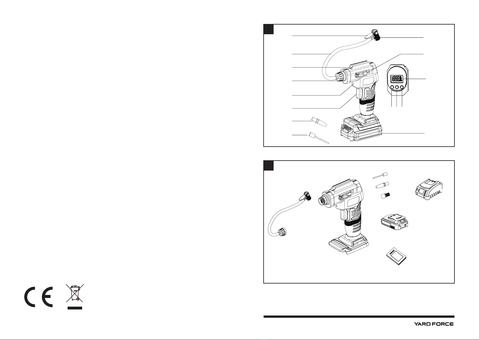
Fitting the air hose (Fig. G)
1. Remove the battery pack from the air pump.
2. Insert the air hose connector (8) into the open end of the air pump then tighten it by
turning clockwise.
3. To remove, turn the air hose connector (8) anti-clockwise and remove the air hose.
Inflating with the air hose
1. The air chuck (1) on the air hose (10) can be used to inate tires or any object with a
valve stem that can t into the air chuck opening.
2. Place the air chuck (1) on the valve stem.
3. Push the air chuck (1) down so that the thread section of the valve stem is inside the air
chuck (1).
4. Clamp the end of the air chuck (1) down onto the valve stem by pressing the air chuck
clamp (11) down until it locks into place.
5. To remove, lift the air chuck clamp (11) and remove the air chuck from valve stem.
Charging the battery pack
NOTE: Remove the battery pack from the charger after it has been fully charged.
NOTE: Battery should be fully charged before rst use.
NOTE: Make sure the mains voltage is the same as rating label which is located on the
charger.
1. Connect the charger to a power supply. Red LED will light up.
2. To insert the battery pack into the charger, align the raised ribs of the battery pack with
the grooves of the charger then push it in. (Fig. C)
3. The red LED light of the charger will light up and then the green light ashes during
normal charging.
4. After charging is complete, the charger light will turn to a solid green light.
5. Once the battery is fully charged , depress the battery release button and then remove
the battery pack. (Fig. C)
Power indicator (Fig. D)
This Li-Ion battery pack is equipped with a power indicator which is used to show the battery
pack’s remaining charge. Press the power indicator button to check battery charge as picture
showed. The indicator will stay lit for approximately 4 seconds.
To obtain the best life from the battery
1. Never allow the battery to completely discharge before recharging. The battery pack
should be placed on the charger whenever the battery pack is noticeably running down
or the tool no longer performs a task it previously performed.
2. Avoid conducting short charges. Make sure that the battery is fully charged each time by
allowing the charger to complete its full charging cycle.
3. Avoid allowing loose items like screws or nails etc. to be stored with battery packs as
these or similar items can short battery packs and cause a re or explosion.
4. Always unplug the charger when not in use and store in a dry and secure place.
5. Avoid charging or storing your battery in temperatures below 5°C and above 45°C.
6. After use, allow the battery pack to cool down for approximately 30 minutes before
attempting to recharge.

20 21
Inflating with the air hose and adapters (Fig. H)
1. The air hose (10) can be used with adapters to inate different objects.
2. Insert adapter into the air chuck (1) and it locks into place.
Switching on and setting the digital pressure gauge (Fig. I)
1. The digital pressure gauge can be used to set the pressure of the inated objects and
monitor the pressure inside the inated object.
Press the power button (15) to switch on the digital pressure gauge.
2. To switch between PSI, BAR or KPA modes
- Press the digital pressure gauge power button (15) to select the desired measured unit.
Setting digital pressure gauge for automatic shut off
1. With the digital pressure gauge (12) switched on, press and hold down (+) or (-) button to
select desired shutoff pressure.
Note: Numbers will flash while setting pressure. Holding buttons down will make the
pressure number increase or decrease faster.
2. When the desired pressure has been selected, begin inating. The air pump will shut off
once the set pressure is reached.
LED worklight (Fig. J)
1. The LED worklight (7) will switch on when the power button (15) is pressed.
2. The LED worklight (7) will stay on when the air pump is switched on. When the air pump
is switched off, the LED worklight will turn off after 30 seconds.
Starting and stopping (Fig. K)
1. To switch the air pump on, press and hold the power and mode button (15) till the digital
pressure gauge (12) is on.
2. Once the digital pressure gauge has switched on, select the desired shutoff pressure.
3. Depress and hold the trigger switch (6) to start pumping air.
4. After a few seconds release the trigger switch (6) and the air pump will continue running.
The air pressure will appear on the digital pressure gauge (12) as the object is being
inated.
5. To turn the air pump off, press the trigger switch (6) again.
6. After the pre-set pressure is reached, the air pump will turn off automatically.
OPERATION MAINTENANCE AND STORAGE
Cleaning
1. Regularly clean the air pump's housing with a soft cloth, preferably after each use. If the
dirt does not come off, use a soft cloth moistened with soapy water.
2. Never use solvents such as petrol, alcohol, ammonia water etc. These solvents may
damage the plastic parts.
Maintenance
1. The air pump has been designed to operate over a long period of time with a minimum
of maintenance. Continuous satisfactory operation depends upon proper care and
regular cleaning.
2. The air pump should only be repaired by an authorized service centre. There is no
serviceable parts that can be repaired by the user.
Storage
1. Thoroughly clean the air pump and its accessories before storage.
2. Store the air pump and its accessories out of the reach of children in a stable and secure
place.
Disposal
Dispose appliances according to the regulations and requirements of your local
council. If appliances are disposed in landlls or dumps, hazardous substances
may leak into the ground water and get into the food chain, damaging your health
and well-being.
TROUBLESHOOTING
Problem Possible causes Possible solutions
Air pump cannot
start.
Battery not installed
properly. Insert the battery again.
Battery not charged. Charge the battery.
No pressure.
Adaptor not tted properly. Fit the adaptor properly.
Pump is not working. Repair by an authorized
service centre.
Pump operates but
object does not
inate.
Adaptor is not tted
properly. Fit the adaptor properly.
Adaptor is not clean. Clean the adaptor.
Incorrect adaptor. Use the correct adaptor.

22
To the provisions of Council Directives
We
MEROTEC GmbH
Otto-Brenner-Str. 8, 47877 Willich, Germany
Declare that the product:
Description: 20V Air Pump
Model No. TB-HT09-20
Function: inating car and bicycle tyres
Complies with the essential health and safety requirements of the
following directives:
Machinery Directive 2006/42/EC
Electromagnetic Compatibility Directive 2014/30/EU
EC Directive 2011/65/EU and its amendment Directive (EU) 2015/863 (RoHS)
Standards and technical specification referred to:
EN ISO 12100:2010
EN 60745-1:2009+A11:2010
EN 55014-1:2017
EN 55014-2:2015
Authorized Signatory
Date: 18.01.2021
Signature:________________________
Place: Willich
Name: Ronald Menken
General Manager
MEROTEC GmbH
Otto-Brenner-Str. 8
D-47877 Willich
CE DECLARATION
This manual suits for next models
1
Table of contents
Popular Water Pump manuals by other brands

Oase
Oase Aquarius Eco Expert 22000 operating instructions

Lincoln
Lincoln 85622 Service & operating manual

fluid-o-tech
fluid-o-tech MG 200 Series Refurbishing Instructions

Pfeiffer Vacuum
Pfeiffer Vacuum HILOBE 1004 operating instructions

Metabo
Metabo TPF 18 LTX 2200 Original instructions

DODA
DODA Super ME 80 Use and maintenance manual