catec EE210 User manual

The EE210 sensor, available for wall or duct mounting as well as with remote probe, is designed for highly accurate measurement
of humidity and temperature in demanding climate control applications. The EE210 incorporates the E+E humidity and temperature
sensor HCT01.
For use in special applications do not hesitate to contact E+E Elektronik or a local distributor.
GENERAL
• For accurate measurement it is essential that the temperature of the probe and mainly of the sensing head is same as the
temperature of the air to measure. Avoid mounting the sensor in a way which creates temperature gradients along the probe.
• The sensor and mainly the sensing head shall not be exposed to extreme mechanical stress.
• The sensor must be operated with the filter cap on at all times. Do not touch the sensing element inside the sensing head.
• While replacing the filter cap (because of pollution for instance) against an original spare one please take very good care to
not touch the sensors.
CAUTION
USER‘S GUIDE
EE210 - Humidity and Temperature Sensor for
demanding Climate Control Applications
USB configuration adapter HA011066
Product configuration software EE-PCS (free download: www.epluse.com/EE210)
Power supply adapter V03 (see data sheet Accessories)
Protection cap for 12 mm probe HA010783
SCOPE OF SUPPLY
Model
EE210
Wall mount
(Type PA)
EE210
Duct mount
(Type PB)
EE210
Remote version
(Type PC)*
EE210-P
Remote probe* for
Type PC
Additionally for all
EE210 with RS485
interface
EE210 according ordering guide
Cable gland (2 pcs.)
Mounting materials
Mounting ange
Inspection certificate according
to DIN EN10204 - 3.1
Quick Guide -
EE210 RS485 Setup
* EE210-P is not included in the Scope of Supply of the EE210 Type PC
ACCESSORIES
Turfschipper 114 | 2292 JB Wateringen | Tel. +31 (0)174 272330 | www.catec.nl | info@catec.nlTurfschipper 114 | 2292 JB Wateringen | Tel. +31 (0)174 272330 | www.catec.nl | info@catec.nl
ME ETI NSTR UME NTATI E

EE210-HT6 EE210-HT6
20...30 V DC RL<500 Ohm
11...30 V DC RL<50 Ohm
Output: 4-20 mA
Output:
Modbus RTU or
BACnet MS/TP
15...35 V DC
24 V AC ±20 %
OUT1
OUT2
Output: 0-5 V
0-10 V
0-20 mA
15...35 V DC
24 V AC ±20 %
V
mA V
mA
OUT1
OUT2
EE210-HT3
EE210-HT2/3/5
EE210-HT2/3/5
EE210-HTx3 EE210-HTx3
CONNECTION DIAGRAM
ONLYFORREMOTEPROBE!
ONLYFORREMOTEPROBE!
Important: The EE210-HT6 (4...20 mA, two-wire) with display operates correctly only if both outputs are connected.
Bus termination resistor 120 Ω (jumper)
Selection ouput signal U / I
conguration connector
DIMENSIONS / MOUNTING
FOR CONDUIT
INSTALLATION
CABLE GLAND M16x1.5
~55 mm
~2.16“
Ø 12 mm
Ø 0.47“ 60 ±0.3mm
2.36 ±0.11“
Ø > 16 mm
Ø > 0.63“
6 mm
0.24“
90 ±0.3mm
3.54 ±0.11“
Ø > 13 mm
Ø > 0.51“
101 mm
3.98“
19 mm
0.75“
90 ±0.3mm
3.54 ±0.11“
46 mm
1.81“
5 mm
0.2“
80.6 mm
3.17“
106 mm
4.17“
GASKET
Length according to ordering guide
Type PB
Type PC
EE210P
Type PA
L = lter cap mm (inch)
Membrane 34 (1.4“)
Stainless steel 33 (1.3“)
Mounting flange
in the scope of supply for
Type PA and PC
EE210 with cable gland: Use a matching wrench to install the cable gland (in the scope of supply) onto the EE210 enclosure.
EE210 with conduit connection for the North American market: use a flat screwdriver to knock open the blind, carefully, in order
to avoid damaging the electronics inside the enclosure. The conduit adapter is not included in the scope of supply. The M16x1.5
opening for the cable gland shall be tightly closed using the blind plug included in the scope of supply.

LED INDICATION
EE210P (type PC)
Factory Setup:
The display shows the two parameters selected for output 1 and output 2 (according to ordering
code). For digital output versions the display shows RH and T.
User Setup:
The user can change the display layout to 1, 2 or 3 lines and select the
parameters to be displayed by using EE-PCS Product Configuration Software (free download
from www.epluse.com/configurator) and the optional USB configuration adapter (not included in
the scope of supply).
Important: The EE210-HT6 (4...20 mA, two-wire version) with display operates correctly only if
both outputs are connected.
DISPLAY
Please note:
EE210P is an intelligent probe with digital output and as such it is interchangeable. In case the probe or its cable gets destroyed or if a
longer cable is needed, please order a replacement probe according to EE210 data sheet. The replacement probe shall be installed as
described above.
Important:
Make sure that the cable glands are closed tightly for both EE210P probe cable and for the power supply and outputs cable. This is
necessary for assuring the protection class (IP class) of the enclosure according to EE210 specication, as well as for stress relief at
the screw terminals on the EE210 board.
The EE210P remote probe for EE210-HTxxPCshall be ordered and it is supplied as separate item. EE210P is to be connected to the
EE210 by the user.
• Install first the cable gland (included in EE210 scope of supply) onto the EE210 enclosure.
• Before connecting the probe, disconnect the EE210 power supply.
• Insert the EE210P cable through the cable gland and connect it to the screw terminals according to the connection diagram
below.
SELECTION OUTPUT SIGNAL U/I
The factory setup of the output signal and scaling corresponds to the type number as ordered.
The output signal (voltage or current 3-wire) can be selected with the DIP switch on the main electronics board (see picture PCB
EE210-HT2/3/5). This does not impact on the scaling of the outputs, which can be changed using USB configuration adapter and the
EE-PCS.
Examples
Factory setup: voltage output 0-5 V or 0-10 V corresponds to 0…100% RH.
After switching from U to I: current output 0…20 mA corresponds to 0…100% RH.
A change of the current output range for instance to 4-20 mA (3-wire) can be made subsequently with the USB configuration adapter
and EE-PCS.
Factory setup: current output 0-20 mA corresponds to -10…50 °C.
After switching from I to U: voltage output 0-10 V corresponds to -10…50 °C.
A change of the voltage output range for instance to 0-5 V can be made subsequently with the USB configuration adapter and
EE-PCS.
Green LED
Information during normal operation
Blue LED
Information during setup with the optional USB
conguration adapter HA011066 and the EE-PCS
Product Conguration Software
on = everything OK on = USB ick connected to PC, no communication
with EE-PCS
ashing = the main board does not recognize the
measurement electronics inside the RH probe
ashing = communication in progress with EE-PCS
o = no power supply or main board failure o =USB ick not connected to PC

DIGITAL SETTINGS
HARDWARE BUS TERMINATION
If required, the bus termination shall be realized with 120 Ohm resistor, jumper on the board.
• Jumper mounted = bus terminated
• Jumper not mounted = bus not terminated
ADDRESS SWITCH
Address Switch
Address Switch
Address setting via EE-PCS Product Configuration Software
All DIP switches at position 0 → address has to be set via
Product Configuration Software
Factory setting: 242 (permitted values: 1…247).
Example: Slave address is set via configuration software.
Address setting via DIP switch
Setting the DIP switches to any other address than 0, overrules the
slave address set via configuration software (permitted values: 1…247).
Example: Slave address set to 11 (= 0000 1011 binary).
00000000
0
1
11010000
0
1
DIGITAL SETTINGS
Factory settings Selectable values
Baud rate 9600 9600, 19200, 38400, 57600, 76800, 115200
Data bits 8 8
Parity EVEN None, odd, even
Stop bits 11 or 2
Slave address 242 1...247
ID address, baud rate, parity and stop bits can be set via:
1. EE-PCS, Product Configuration Software and the appropriate configuration cable.
2. Modbus protocol in the register 60001 (0x00) and 60002 (0x01). See Application Note Modbus AN0103
(available on www.epluse.com/EE210)
The measured values are saved as a 32 bit float value and as 16 Bit signed integer, see the Modbus Register map below.
The serial number as ASCII-code is located at read register address 30001-30008 (16 bit per address).
The firmware version is located at register address 30009 (bit 15...8 = major release; bit 7...0 = minor release).
The sensor name is located at register address 30010.
MODBUS REGISTER MAP
FLOAT 32 bit (read regier):
Function code /
Regier number1) [Dec] Regier address2) [Hex] Parameter name Unit3)
30026 0x19 temperature [°C], [°F]
30028 0x1B relative humidity [%]
30030 0x1D water vapour partial pressure [mbar], [psi]
30032 0x1F dew point temperature [°C], [°F]
30034 0x21 wet bulb temperature [°C], [°F]
30036 0x23 absolute humidity [g/m³], [g/ft³]
30038 0x25 mixing ratio [g/kg], [gr/lb]
30040 0x27 specic enthalpy [kJ/kg], [BTU/lb]
30042 0x29 fro point temperature [°C], [°F]

INTEGER 16 bit (read regier):
Function code /
Regier number1) [Dec] Regier address2) [Hex] Parameter name Unit3) Scale4)
30301 0x12C temperature [°C], [°F] 100
30302 0x12D relative humidity [%] 100
30303 0x12E water vapour partial pressure [mbar], [psi] 100
30304 0x12F dew point temperature [°C], [°F] 100
30305 0x130 wet bulb temperature [°C], [°F] 100
30306 0x131 absolute humidity [g/m³], [g/ft³] 100
30307 0x132 mixing ratio [g/kg], [gr/lb] 100
30308 0x133 specic enthalpy [kJ/kg], [BTU/lb] 100
30309 0x134 fro point temperature [°C], [°F] 100
INTEGER 16 bit (read and write regier):
Function code / Regier number1) [Dec] Regier address2) [Hex] Parameter name
60001 0x00 Slave-ID5) modbus address
60002 0x01 Modbus protocol settings6)
INFO (read regier):
Function code / Regier number1) [Dec] Regier address2) [Hex] Parameter name
30001 0x00 Serial number (as ASCII)
30009 0x01 Firmware version
30010 0x09 Sensor Name
1) Regier number arts from 1
2) Regier address arts from 0
3) The choice of measurement units (metric or non-metric) mu be done in the ordering guide, see EE210 data sheet. Switching from metric to non-metric or vice versa by using the EE-PCS is not possible.
4) 100 is scale 1:100 (2550 is equivalent to 25.5 °C)
5) If the ID is set via DIP-switch the response will be NAK
6) For Modbus protocol settings please see Application Note Modbus AN0103 (available on www.epluse.com/EE210)
READING EXAMPLE
Example of MODBUS RTU command for reading the temperature (float value) T = 24,270019 °C from the register 0x19:
Device EE210; slave ID 242 [F2 in Hex]
Reference document, chapter 6.3: http://www.modbus.org/docs/Modbus_Application_Protocol_V1_1b.pdf
Reque [Hex]: F2 03 00 19 00 02 01 0F
Modbus ID
address Function code Starting
address Hi
Starting
address Lo
No. of
regier Hi
No. of
regier Lo CRC
Reque
[Hex]: F2 03 00 19 00 02 01 0F
Response [Hex]: F2 03 04 29 00 41 C2 80 A1
Modbus ID
address
Function
code Byte count Regier 1
value Hi
Regier 1
value Lo
Regier 2
value Hi
Regier 2
value Lo CRC
Response
[Hex]: F2 03 04 29 00 41 C2 80 A1
For decoding of float values (stored according standard IEEE754), please refer to AN0103, chapter 7.
Example of decoding:
Response [Hex]: Value in decimal
Byte 1
(Regier 2 - Hi)
Byte 2
(Regier 2 – Lo)
Byte 3
(Regier 1 - Hi)
Byte 4
(Regier 1 - Lo)
41 C2 29 00 24,270019

TECHNICAL DATA
(Modification rights reserved)
Measured Values
Relative Humidity (RH)
Working range 0...100 % RH
RH accuracy1) (incl. hysteresis, non-linearity and repeatability)
Wall & duct version:
-15...40 °C (5...104 °F) ≤90 % RH ±(1.3 + 0.003*measured value) % RH
-15...40 °C (5...104 °F) >90 % RH ± 2.3 % RH
-40...60 °C (-40...140 °F) ±(1.5 + 0.015*measured value) % RH
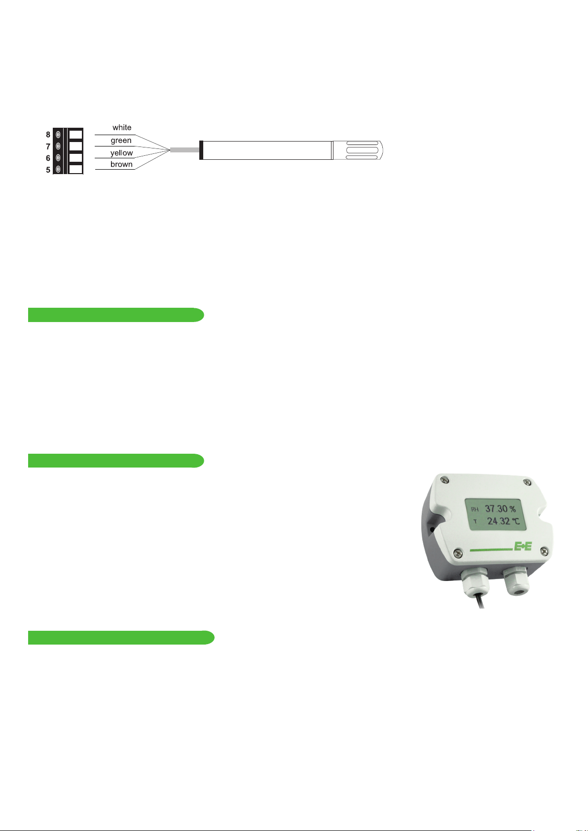
Remote probe version
at 20 °C (68 °F) ±2.5 % RH
Temperature (T)
Sensor Pt1000 (tolerance class B, DIN EN 60751) integrated in HCT01
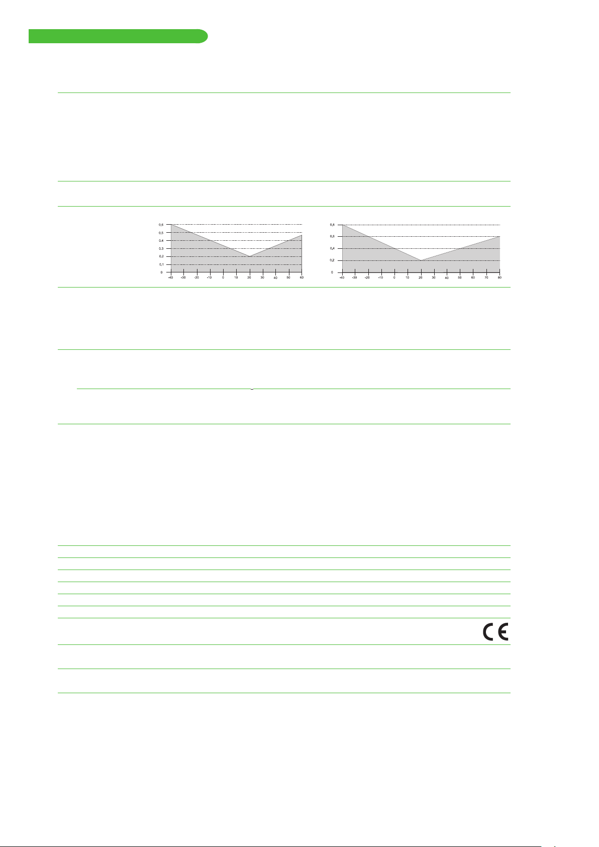
T-accuracy wall & duct remote probe
± ∆ °C
°C
± ∆ °C
°C
Outputs
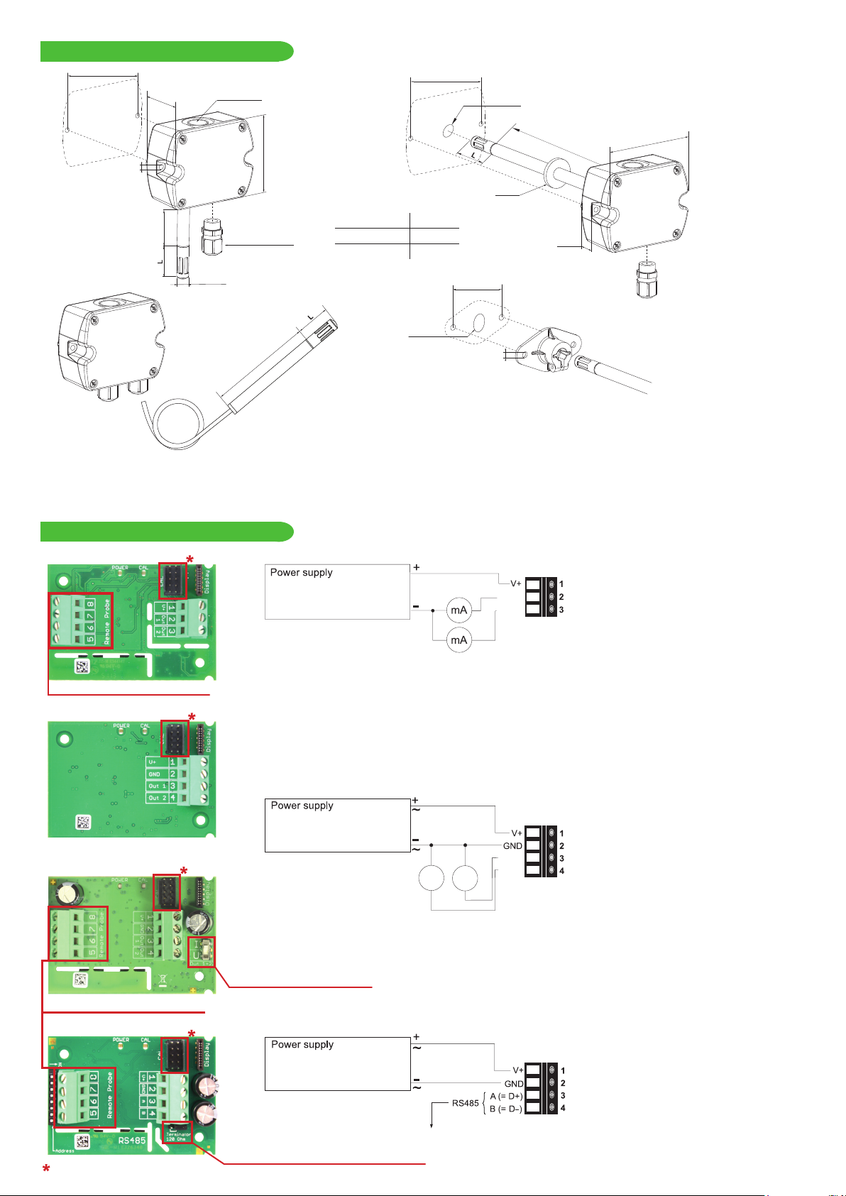
Analogue output 0-5 V / 0-10 V -1 mA < IL< 1 mA
4-20 mA (2-wire) RL≤ 500 Ohm
0-20 mA (3-wire) RL≤ 500 Ohm
Digital output RS485 (BACnet MS/TP or Modbus RTU), max. 32 EE210 in one bus
General
Power supply
for 4-20 mA, 2-wire 10 V + RLx 20 mA < V+ < 30 V DC
for 0-20 mA, 3-wire 15-35 V DC2) or 24V AC ±20 %
for 0-5 V / 0-10 V / RS485
Current consumption at 24 V
Voltage output DC supply max. 12 mA; with display max. 23 mA
AC supply max. 34 mArms; with display max. 49 mArms
Current output
2-wire DC supply max. 40 mA; with display max. 40 mA
3-wire DC supply typ. 33 mA; with display max. 44 mA
AC supply typ. 65 mArms; with display max. 84 mArms
Digital interface DC supply typ. 5 mA; with display max. 20 mA
AC supply typ. 15 mArms; with display max. 35 mArms
Display 1, 2 or 3 lines, user configurable, optional with backlight
Electrical connection Screw terminals, max. 1.5 mm2
Housing material Polycarbonate, UL94V-0 (with Display UL94HB) approved
Protection class IP65 / NEMA 4
Cable gland M16 x 1.5
Probe cable (type PC) PVC, Ø 4.3 mm, 4 x 0.25 mm2, Length: 1.5 or 3 m (4.9 or 9.8 ft)
Electromagnetic compatibility EN61326-1 EN61326-2-3
Industrial Environment
Temperature ranges Working: -40...60 °C (-40...140 °F) (-40...80 °C / -40... 176 °F for probe EE210P)
model without display Storage: -40...60 °C (-40...140 °F)
Temperature ranges with display Working: -20...50 °C (-4...122 °F) (-40...80 °C / -40... 176 °F for probe EE210P)
model with display Storage: -20...60 °C (-4...140 °F)
1) Traceable to intern. standards, administrated by NIST, PTB, BEV,... The accuracy statement includes the uncertainty of the factory calibration with an enhancement factor k=2
(2-times standard deviation). The accuracy was calculated in accordance with EA-4/02 and with regard to GUM (Guide to the Expression of Uncertainty in Measurement).
2) USA & Canada: class 2 supply required, max. supply voltage 30 V

SETUP AND ADJUSTMENT
The EE210 is ready to use and does not require any configuration by the user. The factory setup of EE210 corresponds to the type
number ordered. For ordering guide please see data sheet at www.epluse.com/ee210. If needed, the user can change the factory
setup by using the USB configuration adapter (cod HA011066) and the EE-PCS, Product Configuration Software.
The user can change the scaling and the analogue output signal, the digital settings and perform RH and T adjustment.
Note: The EE210 may not be connected to any additional power supply when using the USB configuration adapter HA011066.
PC
HA011066
EE-PCS PRODUCT CONFIGURATION SOFTWARE
1. Download the EE-PCS Product Configuration Software from www.epluse.com/configurator and install it on the PC.
2. Connect the E+E device to the PC using the USB configuration adapter.
3. Start the EE-PCS software.
4. Follow the instructions on the EE-PCS opening page for scanning the ports and identifying the connected device
5. Click on the desired setup or adjustment mode from the main EE-PCS menu on the left and follow the online
instructions of the EE-PCS
MAINTENANCE
Humidity calibration and adjustment:
Depending on the application and the requirements of certain industries, there might arise the need for periodical humidity calibration
(comparison with a reference) or adjustment (bringing the device in line with a reference).
• Calibration and adjustment at E+E Elektronik
Calibration and/or adjustment can be performed in the E+E Elektronik calibration laboratory. For information on the E+E
capabilities in ISO or accredited calibration please see www.eplusecal.com.
• Calibration and adjustment by the user
Depending on the level of accuracy required, the humidity reference can be:
• Humor 20 Humidity Calibrator, please see www.epluse.com.
• Omniport30 handheld device, please see www.epluse.com/omniport30.
• Calibrated salt solutions, please see www.epluse.com/EE210.
Temperature calibration and adjustment:
Due to the outstanding protection of the Pt1000 temperature sensing element integrated in the E+E HCT01 sensor, a drift of the T
measurement is rather unlikely. If adjustment seems necessary, although the user can perform a one or two point T adjustment with
USB configuration adapter and EE-PCS against a reference of his choice, it is highly recommended to return the device to the
manufacturer for this. The reasons rest on the difficulty of an accurate T calibration in the air. The calibration shall take into account
the self-heating of EE210 with closed enclosure, in its real mounting position and in continuous operation, the impact of the output
current and of the probe orientation to the self-heating, as well as the cooling effect of the air circulation in a climate chamber possibly
used for calibration.
When employed in dusty, polluted environment:
• The filter cap shall be replaced once in a while with an E+E original one. A polluted filter cap causes longer response time of the
device.
• If needed, the sensing head can be cleaned. For cleaning instructions please see www.epluse.com/EE210.

INFORMATION +43 7235 605 0 / [email protected]
Langwiesen 7 • A-4209 Engerwitzdorf
Tel: +43 7235 605-0 • Fax: +43 7235 605-8
LG Linz Fn 165761 t • UID-Nr. ATU44043101
Place of Jurisdiction: A-4020 Linz • DVR0962759
BA_EE210_e // v1.7 // Modification rights reserved
USA
FCC notice:
This equipment has been tested and found to comply with the limits for a Class B digital device, pursuant to part 15 of the FCC Rules. These limits are
designed to provide reasonable protection against harmful interference in a residential installation. This equipment generates, uses and can radiate radio
frequency energy and, if not installed and used in accordance with the installation manual, may cause harmful interference to radio communications.
However, there is no guarantee that interference will not occur in a particular installation. If this equipment does cause harmful interference to radio or
television reception, which can be determined by turning the equipment off and on, the user is encouraged to try to correct the interference by one or
more of the following measures:
- Reorient or relocate the receiving antenna.
- Increase the separation between the equipment and receiver.
- Connect the equipment into an outlet on a circuit different from that to which thereceiver is connected.
- Consult the dealer or an experienced radio/TV technician for help.
CANADIAN
ICES-003 Issue 5:
CAN ICES-3 B / NMB-3 B
Table of contents
Popular Accessories manuals by other brands

WMF
WMF Ambient Pro operating manual

Pro-Ject Audio Systems
Pro-Ject Audio Systems Speed Box SE II Instructions for use

Delta Controls
Delta Controls DNS-24 Application guide

Hyundai
Hyundai WS SENZOR 77 instruction manual

Echo Audio
Echo Audio AudioFire2 owner's manual

SICK
SICK TriSpector1000 operating instructions