Cateye Ergociser EC-5000 Service Manual
2
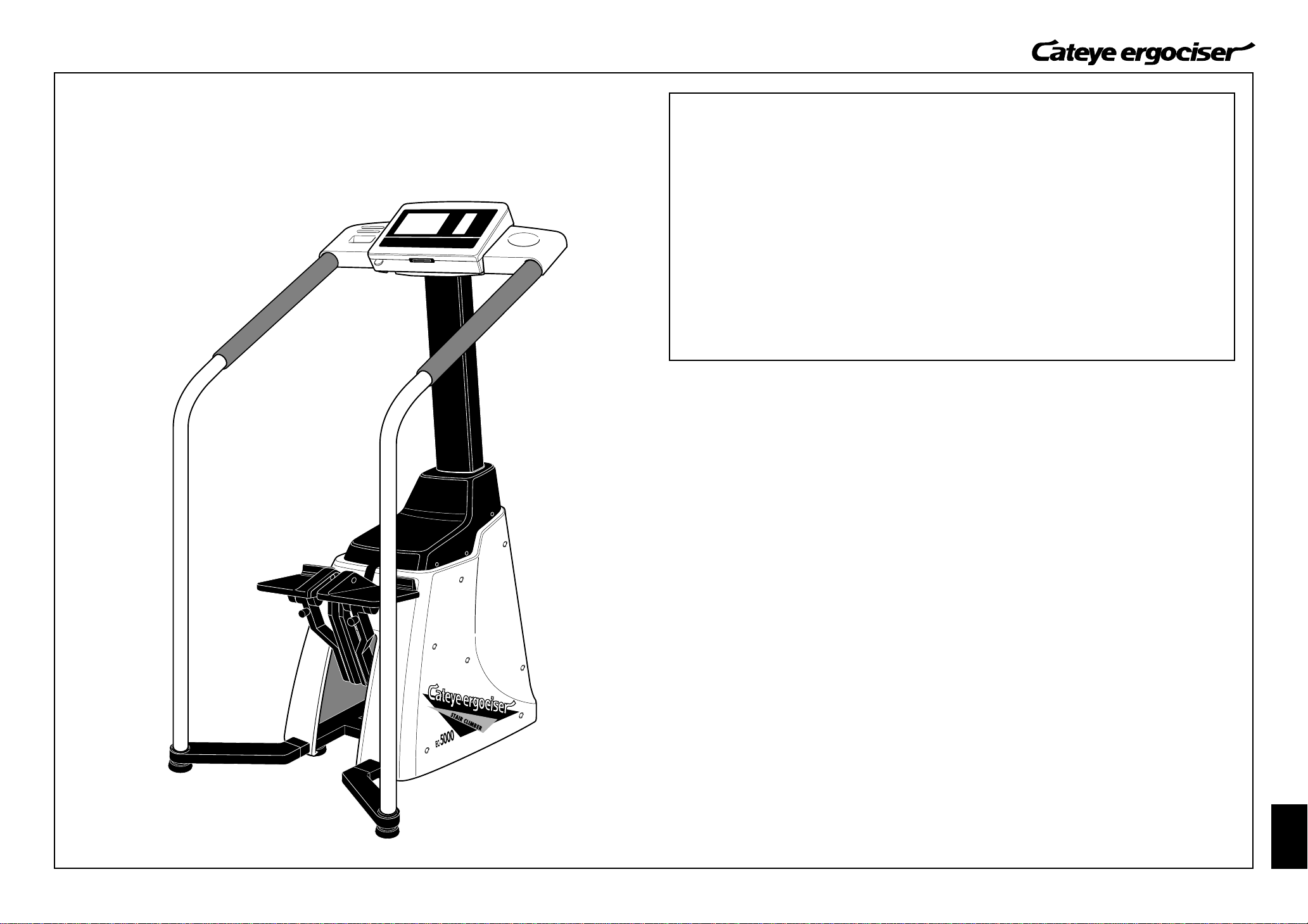
EC-5000
INDEX
INTRODUCTION
• How to Use This Service Manual --------------------------------------------------------------------------------------- 3
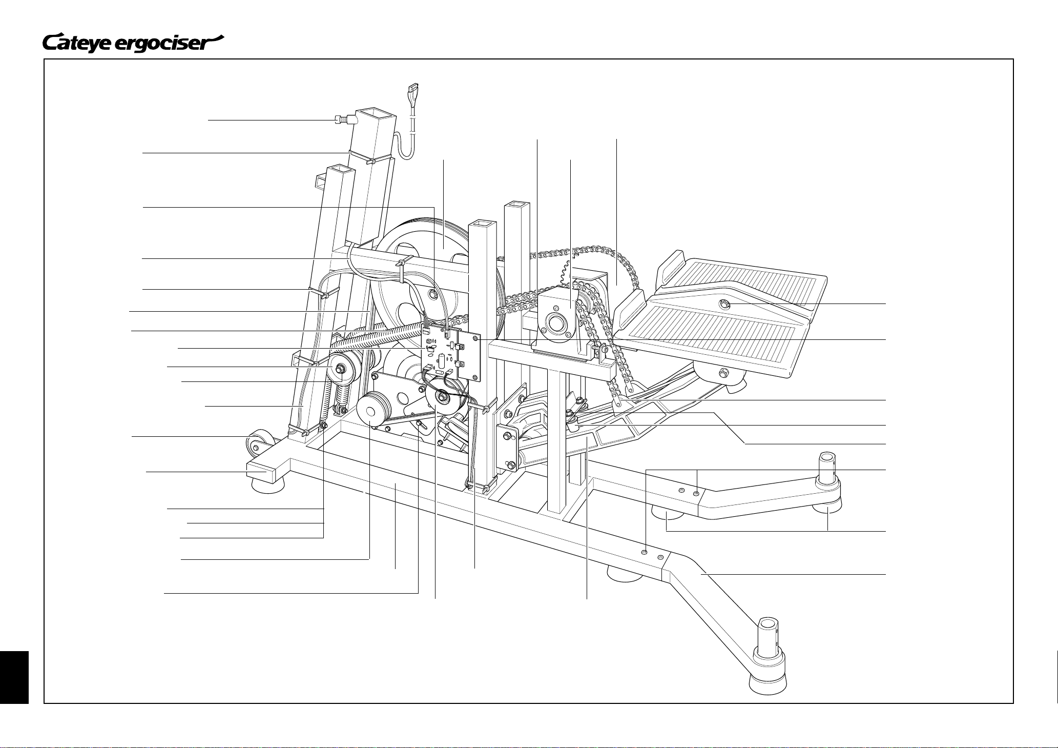
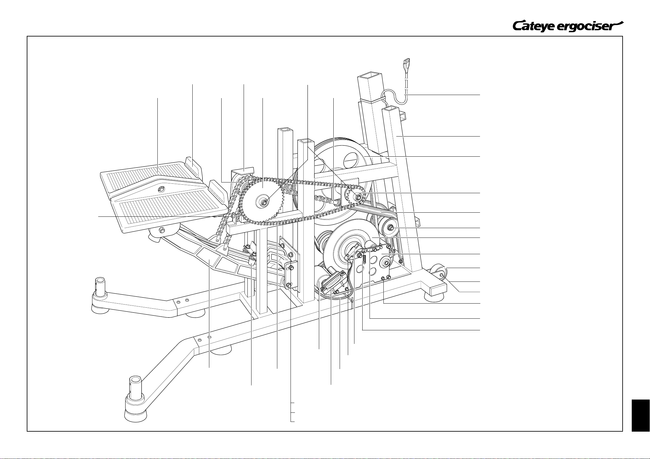
• Name of Parts ------------------------------------------------------------------------------------------------------------- 4~5
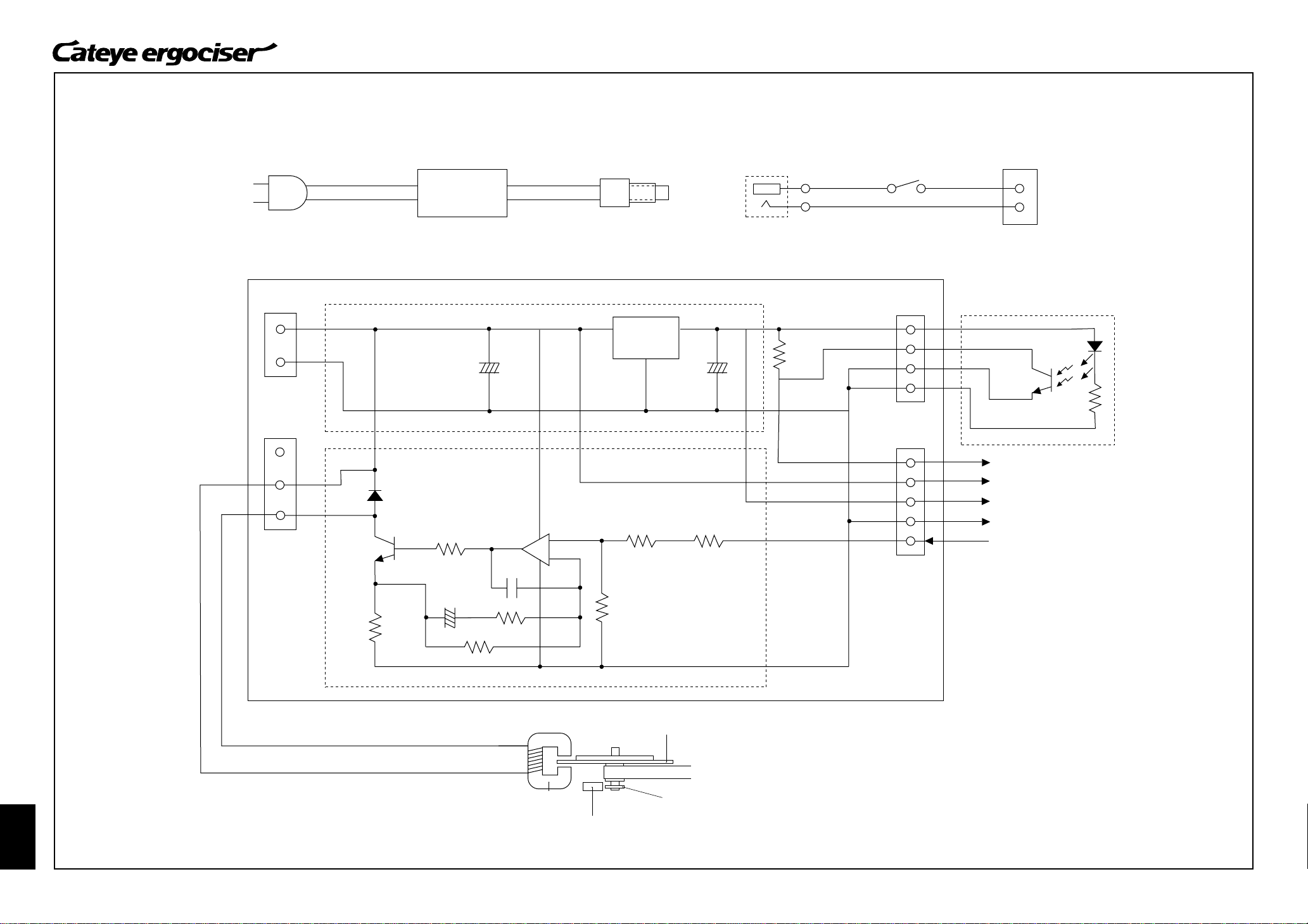
• Circuit Diagram -------------------------------------------------------------------------------------------------------------- 6
Part A
Symptoms of Problems & Causes
T-1: No Display on Control Unit after Power ON
1. Back light does not turn on--------------------------------------------------------------------------------- 7~8
2. Back light turns on----------------------------------------------------------------------------------------------- 9
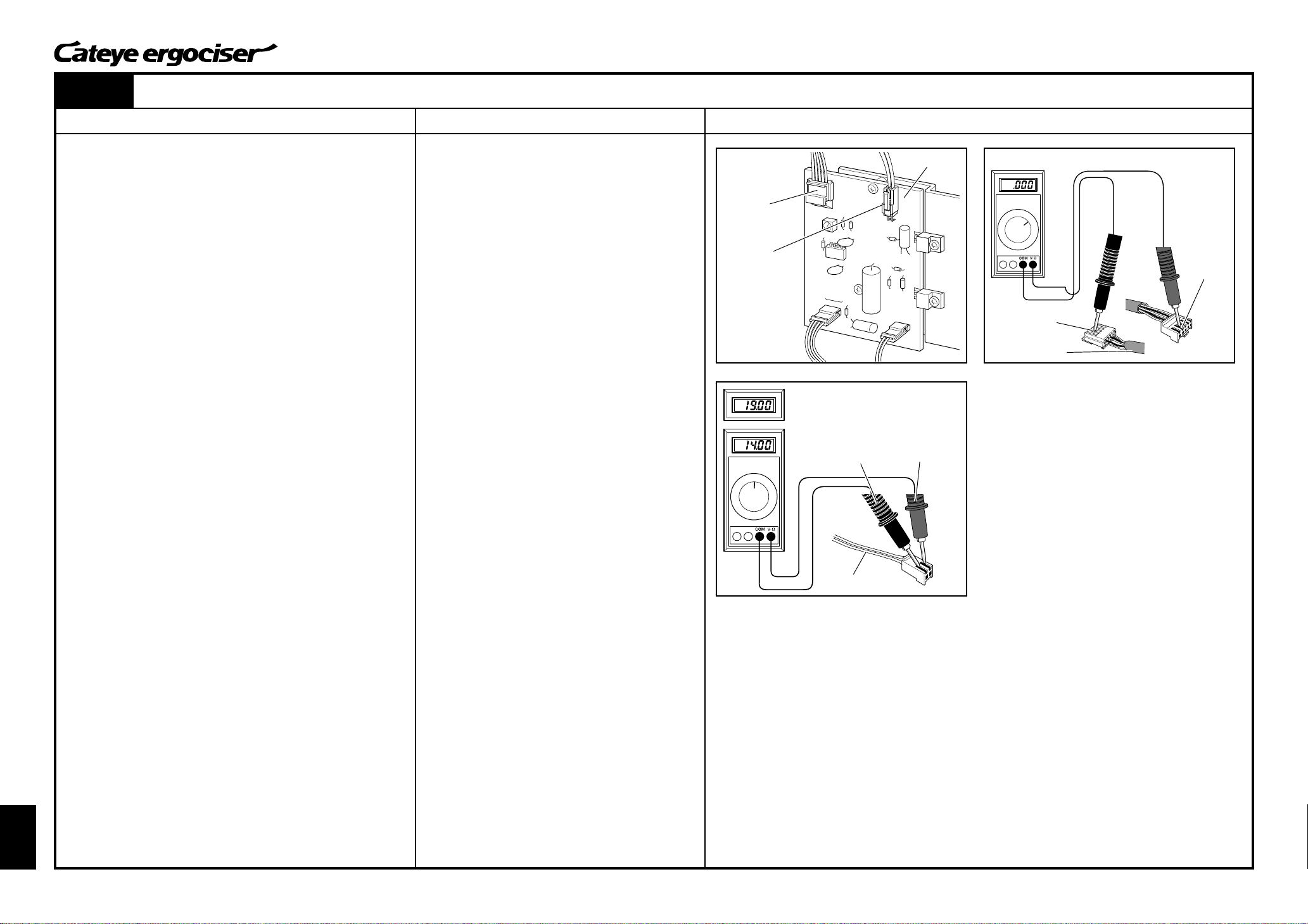
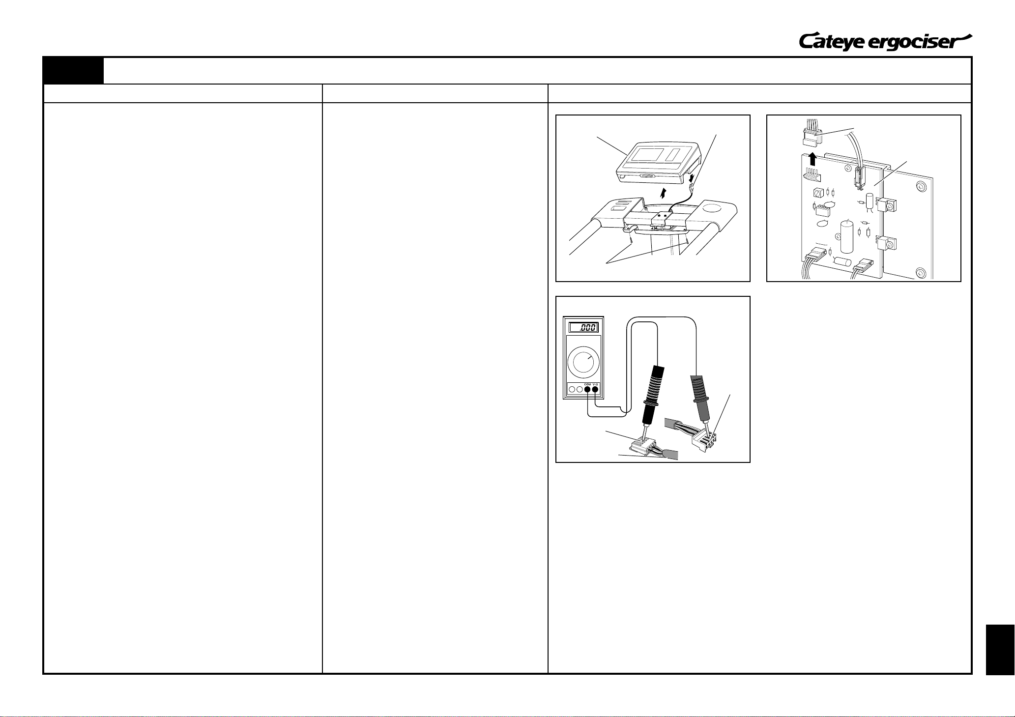
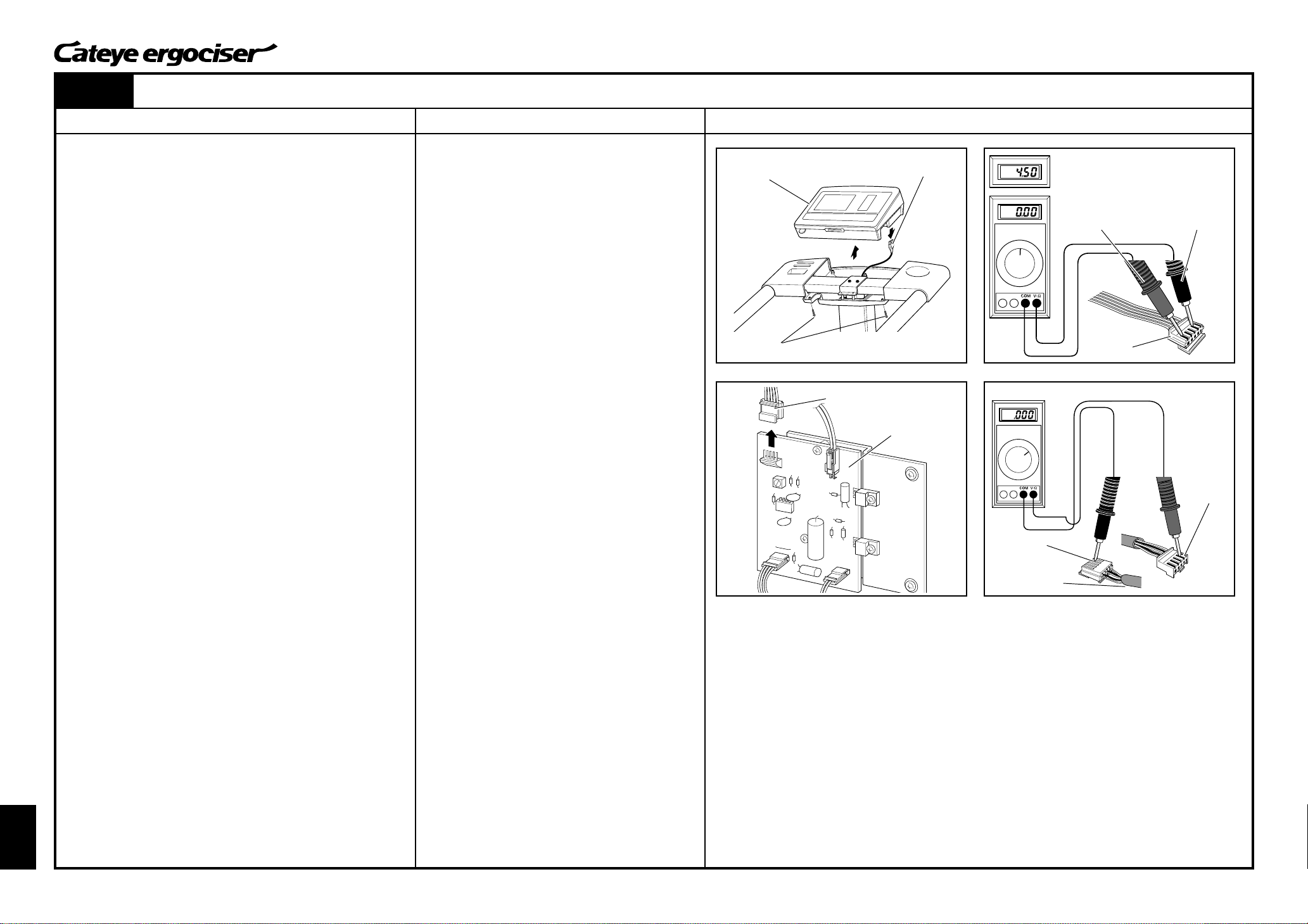
T-2: No Display of Cadence when the Pedal is Rotated --------------------------------------------------10~13
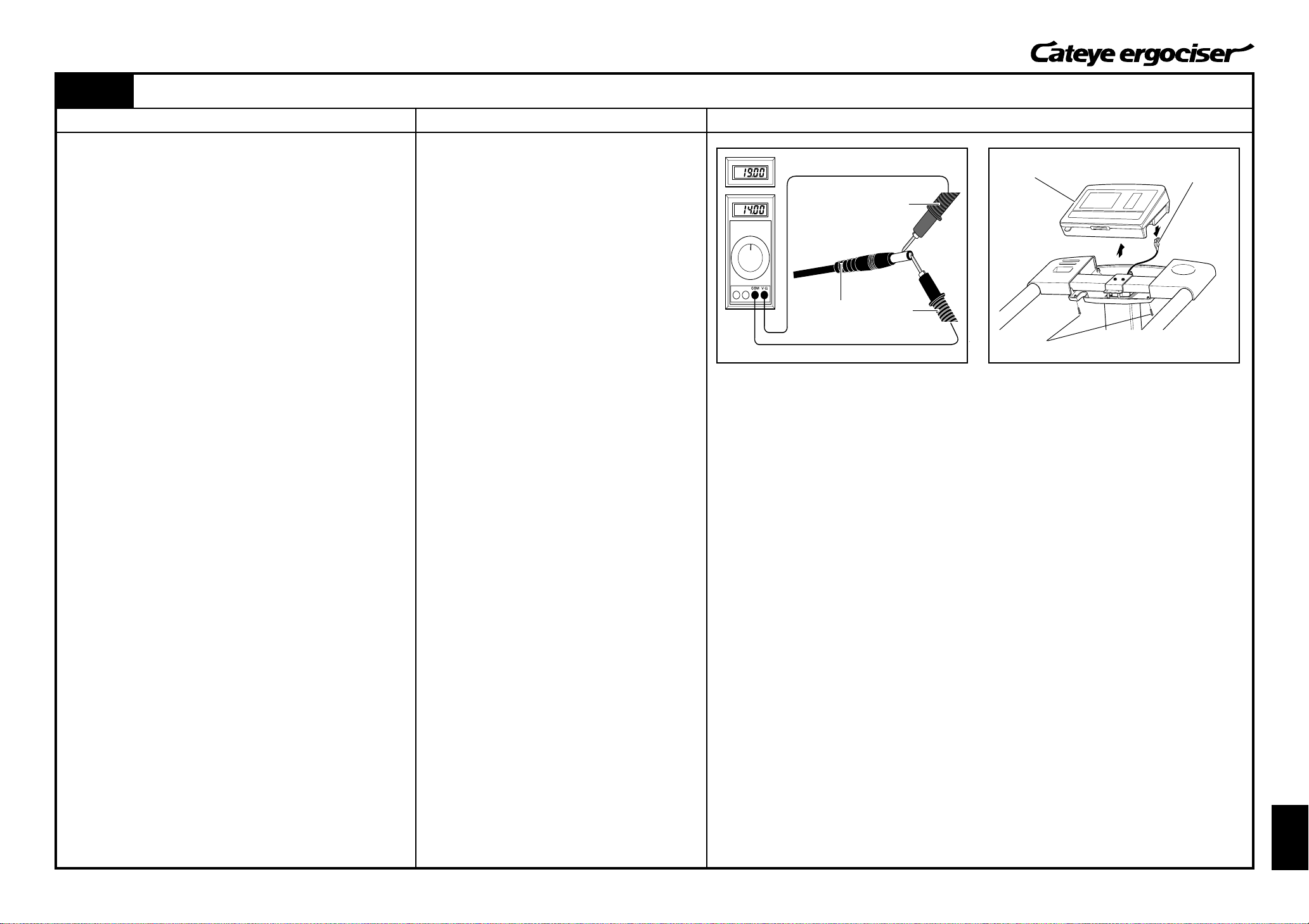
T-3: No Display of Pulse Rate -----------------------------------------------------------------------------------------14
T-4: No Display of Heart Rate (The Case with Wireless Chestbelt Pulse Sensor Kit) ------------15~16
T-5: Improper Display on Control Unit-------------------------------------------------------------------------------17
T-6: No Cadence Control
1. Slower cadence control is not possible--------------------------------------------------------------18~19
2. Faster cadence control is not possible --------------------------------------------------------------20~23
T-7: Pedal will not be Restored to Original Position -------------------------------------------------------------24
T-8: Unusual Noise
1. Continuous and Increasing -----------------------------------------------------------------------------25~26
2. Unusual Noise Synchronized with Pedal Rotation ----------------------------------------------------27
INDEX
Part B
Removing / Mounting the Frame Covers
D-1: Removing the Frame Covers ----------------------------------------------------------------------------- 28
D-2: Mounting the Frame Covers------------------------------------------------------------------------------- 29
Repair Methods
ES-1: Replacing the Wiring within Frame (Inlet Metal Base Set) -------------------------------------------30
ES-2: Replacing the 5P Cable ----------------------------------------------------------------------------------------31
ES-3: Replacing the Power Supply Board-------------------------------------------------------------------------32
ES-4: Correcting the Postion of Solenoid Coil--------------------------------------------------------------------33
ES-5: Replacing the Slenoid Coil Set -------------------------------------------------------------------------------34
ES-6: Replacing the CDC Sensor set-------------------------------------------------------------------------------35
ES-7: Replacing the CDC Sensor Cable---------------------------------------------------------------------------36
ES-8: Correcting the Postion of CDC Sensor---------------------------------------------------------------------37
ES-9: Replacing the Control Unit ------------------------------------------------------------------------------------38
ES-10: Replacing the Button Panel -----------------------------------------------------------------------------------39
MS-1: Replacing the Workload Unit ---------------------------------------------------------------------------------40
MS-2: Replacing the Accelerating Chain ---------------------------------------------------------------------------41
MS-3: Replacing the Pedal Chain ------------------------------------------------------------------------------------42
MS-4: Replacing the V-Belt --------------------------------------------------------------------------------------------43
MS-5: Replacing the Idler Set -----------------------------------------------------------------------------------------44
MS-6: Replacing the Pulley A -----------------------------------------------------------------------------------------45
MS-7: Replacing the V-Belt tension Pulley ------------------------------------------------------------------------46
MS-8: Replacing the Sprocket (Gear for Chains) ----------------------------------------------------------------47
MS-9: Replacing the Shaft Set A -------------------------------------------------------------------------------------48
MS-10: Replacing the Spring--------------------------------------------------------------------------------------------49
MS-11: Replacing the Spring Pulley Set -----------------------------------------------------------------------------50
MS-12: Replacing the Linkstep Set-------------------------------------------------------------------------------51~52
MS-13: Replacing the Pedal Stopper ---------------------------------------------------------------------------------53
MS-14: Replacing the BB Set -------------------------------------------------------------------------------------------54
MS-15: Replacing the Front Reg Cover ------------------------------------------------------------------------------55
MS-16: Replacing the Caster--------------------------------------------------------------------------------------------56
MS-17: Replacing the Rubber Stopper -------------------------------------------------------------------------------57
MS-18: Replacing the Tray-----------------------------------------------------------------------------------------------58
Part C
List of Genuine Parts --------------------------------------------------------------------------------------------------- 59~62