Cattron Excalibur OCU User manual

Excalibur™OCU
User Manual
Part # 9M02-7573-A001-EN

Excalibur
User Manual
2
9M02-7573-A001-EN
Version 3.0
Revision History
VERSION
DATE
NOTES
1.0
Initial Release
2.0
08/2016
Content Update, Styles Update, Support information Update
3.0
06/2019
Branding Update, Integrated Sub-manuals, Updated Declarations
Any information furnished by Cattron™ and its agents is believed to be accurate and reliable. All specifications are subject to change without notice.
Responsibility for the use and application
of Cattron products rests with the end user since Cattron and its agents cannot be aware of all potential
uses.Cattronmakesnowarrantiesastonon-infringementnorastothefitness, merchantability,orsustainabilityofanyCattronproductsforany
specificorgeneraluses.CattronHoldings,Inc.,oranyofitsaffiliatesoragentsshallnotbeliableforincidental
or consequentialdamagesofany
kind. All Cattron products are sold pursuant to the Terms and Conditions of Sale, a copy of which will be furnished upon request. When used as a
tradename
herein, Cattron means Cattron Holdings, Inc. or one or more subsidiaries of Cattron Holdings, Inc. Cattron™, corresponding logos,
and other marks are trademarks or registered trademarks of Cattron Holdings, Inc. Other marks may be the property of third parties. Nothing
hereinprovidesalicenseunderanyCattronoranythirdpartyintellectualpropertyright.

Excalibur
User Manual
3
9M02-7573-A001-EN
Version 3.0
Contents
1. Safety Instructions.......................................................................................................................................................................5
1.1 Warnings............................................................................................................................................................5
2. System Description .....................................................................................................................................................................7
3. General .........................................................................................................................................................................................8
3.1 Radio Transmission ...........................................................................................................................................8
3.1.1 Continuous Transmission...................................................................................................................................8
3.1.2 Radio Interference..............................................................................................................................................8
3.2 Telegram Security..............................................................................................................................................8
3.2.1 Frame Type........................................................................................................................................................8
3.2.2 System Address.................................................................................................................................................8
3.2.3 CRC...................................................................................................................................................................9
3.2.4 Frame Counter...................................................................................................................................................9
3.3 System Parameters............................................................................................................................................9
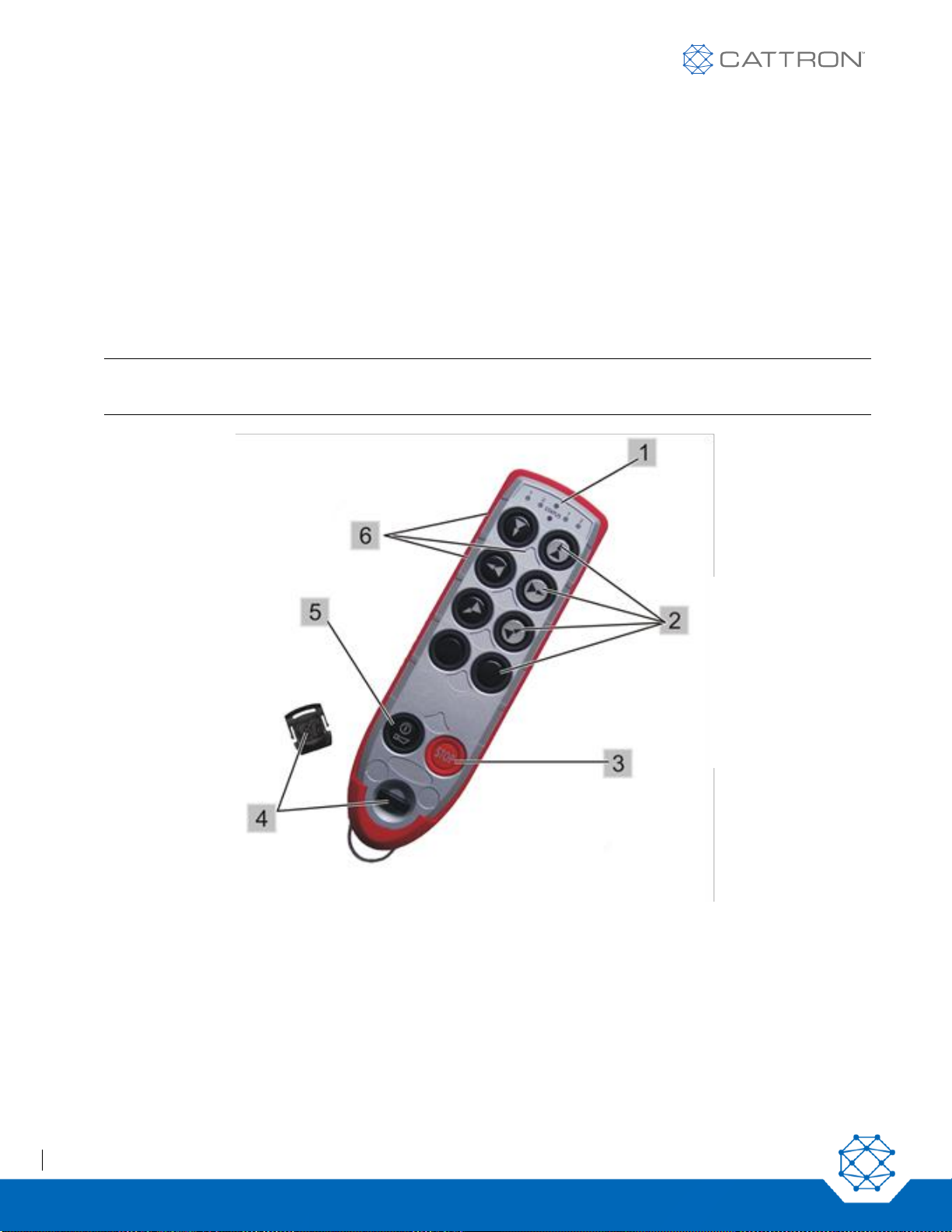
4. Standard Operator Control Unit (OCU)..................................................................................................................................10
4.1 Safe-T-Stop Version.........................................................................................................................................12
4.2 General Information .........................................................................................................................................12
5. Operating Instructions...............................................................................................................................................................14
5.1 OCU First Use..................................................................................................................................................14
5.2 OCU Battery Pack –Removal and Replacement ............................................................................................14
5.3 Charging the Battery........................................................................................................................................14
5.4 Battery Charging..............................................................................................................................................15
5.5 TransKeys........................................................................................................................................................16
5.6 OCU Switch-On Procedure..............................................................................................................................17
6. OCU Maintenance.....................................................................................................................................................................19
6.1 Preventative Maintenance................................................................................................................................19
7. Operating Frequency Selection...............................................................................................................................................20
7.1 Buttons are used to Program the OCU Frequency..........................................................................................20
7.2 Required MCU Configuration...........................................................................................................................20
7.3 Changing the RF Channel................................................................................................................................21
7.4 Activating the Programming Mode...................................................................................................................21
7.5 Selecting the RF Channel................................................................................................................................21
7.6 Reverting to the RF Channel Preset in the TransKey......................................................................................21
7.7 Cancelling RF channel Selection.....................................................................................................................22
7.8 RF Frequency Cluster and Channel Color Code Tables..................................................................................22
7.9 Field Strength Indicator....................................................................................................................................29
7.9.1 Optical Interference Field Strength Display......................................................................................................29
7.9.2 Acoustic Interference Field Strength Output ....................................................................................................29

Excalibur
User Manual
4
9M02-7573-A001-EN
Version 3.0
7.10 Free RF Channel Scan Feature.......................................................................................................................29
7.10.1 RF Channel Change in Scan Mode .................................................................................................................30
8. Hoist Selection...........................................................................................................................................................................31
8.1 Configurable Parameters.................................................................................................................................31
8.2 Storing the Last Selection Via the Electronic Selection Switch........................................................................31
8.3 The Electronic Selection Switch Sequence......................................................................................................31
8.4 Hoists and Enable Selection Buttons for the 10 and 12 Button OCUs.............................................................32
9. Crane Selection .........................................................................................................................................................................35
9.1 General Operating Notes.................................................................................................................................35
9.2 Select Function ................................................................................................................................................35
9.3 Request Function ...............................................................................................................................................35
9.3.1 Operation Following a REQUEST....................................................................................................................36
9.4 RELEASE Function..........................................................................................................................................36
9.5 Select Status Indication on the Cranes............................................................................................................36
9.6 Example Configuration.....................................................................................................................................36
9.7 Operating Notes...............................................................................................................................................38
9.7.1 Stop Command................................................................................................................................................38
9.7.2 MCU Behavior When Switched On..................................................................................................................38
9.7.3 Behavior of the Safety Relays..........................................................................................................................38
9.7.4 MCU Assignment When an OCU is Switched OFF..........................................................................................38
10. Compliance.................................................................................................................................................................................39
CE Declaration of Conformity..........................................................................................................................................................39
RF Compliance..................................................................................................................................................................................39
Unlicensed Bands.....................................................................................................................................................39
Licensed Bands........................................................................................................................................................39
Appendix I: Technical Specifications..............................................................................................................................................40
OCU Technical Specifications..................................................................................................................................40
Battery Charger Technical Specifications.................................................................................................................40
Appendix II: System Fault/Status Messages ................................................................................................................................41
OCU Fault/Status Messages....................................................................................................................................41
Appendix III: Configuration Sheets.................................................................................................................................................42
Example Configuration Sheet for System Model 983127.........................................................................................42
Example Configuration Sheet for System Model 983128.........................................................................................43
Example Configuration Sheet for System Model 983129.........................................................................................44
Example Configuration Sheet for System Model 983130.........................................................................................45

Excalibur
User Manual
5
9M02-7573-A001-EN
Version 3.0
1. Safety Instructions
1.1 Warnings
WARNING statements have been strategically placed throughout all text prior to operating or maintenance
procedures, practices, or conditions considered essential to the protection of personnel or equipment and
property. A WARNING applies each time the related step is repeated. Before starting any task, the WARNINGS
included in the text for the task should be reviewed and understood. WARNINGS appearing in this manual are
included below.
WARNING
More than one remote control system may be used at, around, or nearby your operating facility.
Therefore, before inserting a TransKey, you must insure the correct coded TransKey is selected
for the desired equipment to be operated.
If the wrong TransKey is inserted, other remote controlled equipment located at, around, or nearby
your facility may become operational.
Failure to comply with the above warnings may result in unintended operation of remote controlled
equipment which in turn could result in serious injury or death to personnel and damage to
equipment.
WARNING
Before attempting to use the remote control system, verify the target crane or machine you wish to
operate is under the direct command of your OCU. This is accomplished by operating a non-
motion OCU function such as the horn and observing that the horn sounds on the targeted crane
or machine.
Failure to implement the above may result in serious injury or death to personnel and damage to
equipment.
WARNING
The use of unapproved components or accessories in the systems sold by Cattron and its
subsidiaries is strictly prohibited. Unapproved components are defined as any component not
inspected and sold by Cattron. This also includes any component modified from its intended use
and/or any component exhibiting observable damage or defect.
Use of non-conforming parts, assemblies and accessories may lead to injury or death.
WARNING
Only personnel trained and authorized by Cattron, or personnel under the direct guidance of
Cattron technical staff and while using the appropriate tools, are authorized to carry out board level
maintenance of the equipment.
Component level repair by personnel other than Cattron technical staff is strictly forbidden.
Use of non-conforming parts, assemblies and accessories may lead to injury or death.

Excalibur
User Manual
6
9M02-7573-A001-EN
Version 3.0
WARNING
The remote control system you have purchased is designed to stop in a safe mode under a variety
of conditions. Some examples of these conditions are excessive radio signal interference, loss of
battery and/or electrical power, failure of certain components, operation beyond signal range and
others. Although Cattron and its subsidiaries do not specify the position of the operator when
controlling the equipment, we are aware that some users are instructed and trained by their
employer to ride the equipment in a safe manner. It is imperative that you are prepared for an
unplanned stop of the equipment at any time and do not place yourself or others in a position
where this situation may cause you to fall from the equipment. Failure to use caution may lead to
injury or death.
WARNING
The battery charging unit is designed for use with Cattron Nickel Metal Hydride (Ni-MH) battery
packs. Other battery packs may explode when charged with this device.
Failure to comply with this warning will void our warranty and may result in serious injury or death
to personnel and damage to equipment.
WARNING
Do not open the battery charging unit. Protect the unit against moisture and rain to prevent a fire
hazard or an electric shock.
Operate the battery charging unit in dry indoor spaces only. Do not use the battery charging unit if
the housing or power plug is damaged.
Failure to comply with this warning may result in serious injury or death to personnel and damage
to equipment.

Excalibur
User Manual
7
9M02-7573-A001-EN
Version 3.0
2. System Description
Cattron Portable Remote Control (PRC) systems offer the safety and dependability required for industrial control
applications such as overhead cranes, conveyors, machines, etc.
A remote control system enables an operator to be in the safest and most efficient position for each and every
operation, thereby reducing accidents with associated injury or material damage and simultaneously boosting
efficiency and productivity.
Each system typically includes one Operator Control Unit (OCU) and one Machine Control Unit (MCU), but other
combinations of OCUs and MCUs are possible.
Additionally, different types of MCUs are available and can be paired with the Excalibur OCU. MCU types can be
any of the CattronControl™ range including the CT24-09, CT24-17 Relay MCUs, the CCM12 CANopen, the
J1939 MCU and the MMCU4 which can be configured with other BUS-based interfaces such as Ethernet/IP,
PROFINET, etc., plus relays and Analog and Digital inputs and outputs. Talkback (optional) to LEDs on the
Excalibur OCU can be made from either the CCM12 or MMCU4 MCUs.
The OCU transmits secure data to the MCU, where it is decoded and drives the machine interface (relays, etc.).
Therefore, the machine is under the direct control of the OCU.
The Excalibur OCU is supplied with both Standard System Packages and with Custom Engineered Systems. This
provides a great deal of flexibility to make the solution fit exactly the client’s needs.
A few examples of Standard Systems are shown in Appendix III: Configuration Sheets.
A wide range of optional features are also available for CattronControl systems, including Infra-Red and RF Start-
up and range control options, Multi User control options, etc. More details are available on request.

Excalibur
User Manual
8
9M02-7573-A001-EN
Version 3.0
3. General
With an OCU and a matching MCU, a machine such as a crane or vehicle can be remotely radio controlled,
avoiding the need for a wired connection between the human interface and the controlled device. Several different
control elements are integrated into the OCU housing so commands to the device securely encode into a radio
transmission. The MCU is then able to receive this transmission, securely decode these commands, and provide
suitable interfaces to drive the machine.
3.1 Radio Transmission
The transmission between the OCU and MCU is performed by means of radio communication. Regarding the
actual radio frequency that is used, there are several radio frequency bands available.
A specific RF frequency band and channel will often have been selected prior to delivery of the system.
Depending on the frequency band, a certain number of RF channels are available.
The OCU and MCU must operate on the same RF channel in order to be able to communicate.
3.1.1 Continuous Transmission
Typically, transmission is continuous and the MCU uses this as part of the information required to maintain the
safety relays in an active state. If the MCU does not receive a valid telegram in this mode for a certain period of
time, it automatically turns off, i.e. safety relays and command relays open. Depending on the application, this
time varies from 0.5 s to 2.0 s.
Note: In order to ensure optimum communication between the OCU and the MCU, the OCU should always
ideally be operated with line-of-sight transmission to the MCU antenna. Try to avoid total shielding of
the signal path by metallic and other solid obstructions.
3.1.2 Radio Interference
Signals from other RF-emitting sources might interfere with the radio communication between the OCU and MCU.
If the radio link is affected by these sources, changing the RF channel or even the RF band might be necessary.
3.2 Telegram Security
The transmitted telegram contains several security features, as follows:
3.2.1 Frame Type
Each message has an 8-bit message type identifier that is unique to the equipment in use.
3.2.2 System Address
This system uses a 24-bit addressing scheme, where each OCU/MCU pair shares a common, unique system
address. This system address is contained in every telegram sent by the OCU and is checked by the MCU every
time an RF signal is received. The MCU processes a command only when the address in the telegram and the
address stored in the MCU match. This is a safety measure to ensure that the MCU will act only upon its assigned
OCU.

Excalibur
User Manual
9
9M02-7573-A001-EN
Version 3.0
3.2.3 CRC
The telegram is checked for integrity using a 16-bit CRC. Frames containing a mismatched CRC will be rejected.
3.2.4 Frame Counter
Each message has an 8-bit embedded frame counter that changes on every data frame. This prevents frozen
data and malicious hacking.
3.3 System Parameters
Many system parameters, including the system address and the selected RF channel, are programmed within the
TransKey, this is a removable radio frequency identification device (RFID) located inside the OCU and MCU. It is
pre-programmed by the manufacturer.
Note: Please refer to the separate “Configuration Data” documents for the specific system parameter
settings for your system.

Excalibur
User Manual
10
9M02-7573-A001-EN
Version 3.0
4. Standard Operator Control Unit (OCU)
The Excalibur OCU is a lightweight, palm-sized, extremely rugged customizable controller.
Each OCU is designed to meet a specific control application. Two housing sizes are available that may be
equipped with 6, 8, 10 or 12 pushbuttons.
Each pushbutton may have its specific control function identified from a sheet of self-adhesive labels that is
provided for this purpose.
Referring to Figure 1, advanced operational security and configurability is made possible using a removable RFID
TransKey which, when installed in the OCU, defines and enables the appropriate operating parameters such as
frequency and address. A label with the ID address is affixed to each TransKey.
Note: The OCU TransKey is black, and the MCU TransKey is yellow. Installing an incorrect TransKey
results in a fault indication and the system will not operate.
Figure 1: Excalibur 10 OCU, front view
The ‘STATUS’ LED (located center top) indicates the operational mode and any error messages.
The aperture directly under the ‘STATUS’ LED is an Infra-Red port for IR options.
The four remaining LEDs (two on either side of the ‘STATUS’ LED) indicate either selection information or optional
Talkback information.
1. ‘STATUS’
LED
2. Two-step
operating
pushbuttons
3. STOP
4. TransKey
5. ON/HORN
pushbutton
6. Label fields

Excalibur
User Manual
11
9M02-7573-A001-EN
Version 3.0
Both steps of each individual pushbutton can operate different functions. Typically, the first step controls a
direction or function and the second step controls a speed increment, although it is possible with a step-less drive
to use the second step as accelerate, the first step as hold speed, and the released state as decelerate.
Any function is active only if the respective pushbutton is pressed. When the pushbutton is released, the function
automatically stops.
Pushbutton 5 is for ON/HORN. The second step is assigned to the horn that is typically used in a crane
application.
At startup the pushbuttons are checked for the correct off state.
Figure 2: Excalibur 10/12 OCU, rear view
7. Rechargeable
battery
8. Locking bolt for
the battery
9. Loop for belt clip

Excalibur
User Manual
12
9M02-7573-A001-EN
Version 3.0
4.1 Safe-T-Stop Version
The Safe-T-Stop version of Excalibur is a proven solution based on the Excalibur 6 OCU. It features a raised Stop
button, plus frequency diversity to ensure robust communications in the presence of significant interference as
may be found in public spaces such as theme parks and in busy open industrial areas such as a port or harbor.
This unit would be paired with one of the Frequency Scanning MCUs to achieve a lightweight and reliable solution
to fulfil machine stop requirements. Multiple systems may be used in the same physical area.
All other parameters are common to the standard OCU.
Figure 3: Safe-T-Stop OCU
4.2 General Information
The Excalibur OCU is globally compliant when supplied with an appropriate radio module –additional
certifications may be required for some regions; details are available on request. It has been designed with the
latest generation dual-channel electronics and exceeds the Safety Related Systems requirements for ISO13849
Category 3 PLd.
Excalibur OCUs are equipped with an internal antenna and the typical operating range is in excess of 300 ft
(92 m) for uninterrupted line-of-sight operation. Note that operating range varies with environmental conditions.
Should the OCU go out of operating range and the signal be lost, all motions on the crane or controlled machine
will cease.
Excalibur OCUs have been approved to comply with the RF standards applicable to the region or country of use.

Excalibur
User Manual
13
9M02-7573-A001-EN
Version 3.0
In North America, the Excalibur is compliant with both FCC Part 15 and Industry Canada RSS-210 standards. No
United States of America FCC or Industry Canada license is required for operation of FCC Part 15 or RSS-210
OCUs. These non-licensed OCUs are approved for use in the 902-928 MHz frequency band. See Error!
Reference source not found. for important details.
Other frequency bands including 450-470MHz are available and may require an operating license.
In Europe and other regions, the operating frequency will typically be in the 433-434 MHz or 869MHz license
exempt band; again, other licensed and unlicensed frequency bands are available.
The OCU is powered by a quick-swap rechargeable Nickel Metal Hydride (Ni-MH) battery pack which connects to
the underside of the OCU.
In normal operation, a ‘STATUS’ LED (located centrally) flashes green at 1.25 second intervals. When the battery
voltage becomes low, the ‘STATUS’ LED flashes red at one second intervals to alert the operator that the battery
pack needs to be replaced or recharged. The ‘STATUS’ LED will also illuminate in a series of red blinking
sequences to indicate a specific OCU fault –refer to OCU Fault/Status Messages for a table of these OCU
Fault/Status Messages.
In some applications, four function LEDs located to the right and left of the ‘STATUS’ LED may be configured to
indicate when an OCU function command has been activated at the target machine, or to provide status indication
of machine state, via Talkback.
A global all-purpose plug-in battery pack charger, complete with battery adapter, is available for the OCU. This
allows Ni-MH Battery Packs to be charged from a power source between 100-240 VAC at 50-60 Hz.

Excalibur
User Manual
14
9M02-7573-A001-EN
Version 3.0
5. Operating Instructions
5.1 OCU First Use
The battery pack must be fully charged before using the system for the first time. Charging the battery pack can
take up to 3 hours.
5.2 OCU Battery Pack –Removal and Replacement
Referring to Figure 4, the Battery Pack is located on the back of the OCU.
•To remove the battery pack, release the rotary latch and carefully lift the battery pack out of its compartment.
•To replace the battery pack, carefully insert and lower the battery into the OCU compartment and secure it
into position by tightening the rotary latch.
Figure 4: Battery Pack Removal and Replacement
5.3 Charging the Battery
WARNING
Do not open the battery charging unit. Protect the unit against moisture and rain to prevent a fire
hazard or an electric shock.
Operate the battery charging unit in dry indoor spaces only. Do not use the battery charging unit if
the housing or power plug is damaged.
Failure to comply with this warning may result in serious injury or death to personnel and damage
to equipment.

Excalibur
User Manual
15
9M02-7573-A001-EN
Version 3.0
WARNING
The battery charging unit is designed for use with Cattron Nickel Metal Hydride (Ni-MH) battery
packs. Other battery packs may explode when charged with this device.
Failure to comply with this warning will void our warranty and may result in serious injury or death
to personnel and damage to equipment.
Figure 5: Battery Pack Charging
5.4 Battery Charging
The charger is started by inserting the battery into the cradle, connecting the battery charging cradle to the
charger, and then connecting the charger to the power source. The LED will initially be yellow, and then it
changes to orange when the fast charge starts. When the batteries are fully charged, the charger enters a top-off
charge mode before it transfers to trickle charge mode.
During top-off charge, the LED will be green with short intermittent yellow flashes. When the top-off charge is
completed, the charger enters trickle charge mode and the LED will be green. The battery should be removed
from the charger at this point.
There is a safety timer in the charger to protect against fault batteries, if the safety timer runs out the charger
switches directly to trickle charge mode (no top-off charge) and LED will be continuously green.

Excalibur
User Manual
16
9M02-7573-A001-EN
Version 3.0
If the battery voltage is far below normal, the charger will cut the fast charge current and go to trickle charge
mode. The LED will then indicate “error” by a flickering green and orange light.
If the power source input voltage is turned off, the charger will reset. When the power source is turned on again, a
new charge cycle will start. If new batteries are to be connected, the charger must idle for approximately 15
seconds to make sure all parameters in the microprocessor have been reset. When the charger has been reset,
the LED changes to yellow and a new charge cycle can begin.
When the charger is connected to the power source, the LED will be orange for the first few seconds and then
turn to yellow when the initialization and analysis starts.
If a battery is connected, the actual charging will start a few seconds later when the LED changes to orange. After
the start-timer period has run out (the first few minutes of the charge cycle when the -dV detection is disabled), the
LED will be green for approximately eight seconds. This is a signal for testing and service only. When -dV has
been detected, the start of the top-off charge is indicated with a green LED with intermittent yellow flashes.
The LED is green during trickle charge.
Table 1: Charger LED Sequences
LED SEQUENCES
DESCRIPTION
YELLOW
Battery not connected
YELLOW
Battery Analysis phase
ORANGE
Fast Charge
GREEN with YELLOW FLASH
Top-Off Charge
GREEN
Trickle Charge
GREEN/ORANGE Alternating
ERROR
5.5 TransKeys
WARNING
More than one remote control system may be used at, around, or nearby your operating facility.
Therefore, before inserting a TransKey into an OCU, you must insure the correct coded TransKey
is selected for the desired equipment to be operated.
If the wrong TransKey is inserted into an OCU, other remote controlled equipment located at,
around, or nearby your facility may become operational.
Failure to comply with the above warnings may result in unintended operation of remote controlled
equipment which in turn could result in serious injury or death to personnel and damage to
equipment.
Due to the flexible TransKey concept, it is not uncommon for one OCU to be kept as a spare for multiple cranes or
machines.
Each crane or machine is provided with a unique pair of TransKeys having the same address, this pair of
TransKeys must be inserted into their respective OCU and MCU before carrying out remote control operations.
Once installed, the Transkey may remain in the OCU. However, be sure to remove the Transkey when returning
an OCU for repair so that it can be inserted into the operational OCU.
Two-stage (dual pressure) pushbutton switches are also pre-assigned through TransKey programming for two-
step operation.

Excalibur
User Manual
17
9M02-7573-A001-EN
Version 3.0
5.6 OCU Switch-On Procedure
The correct function of the two switches under the Stop switch must be verified each time the OCU is turned on, to
guarantee its ability to operate (at least one switch) and turn off the OCU on demand.
Referring to Figure 6 below, switch ON the OCU as follows:
1. Fully press the ON/HORN pushbutton once. The ‘STATUS’ LED illuminates red.
2. Fully press the STOP pushbutton. The ‘STATUS’ LED changes to orange.
3. Fully press the ON/HORN pushbutton again. The ‘STATUS’ LED changes to blinking green.
Note: The switch-on sequence must be completed within 10 seconds. The battery cannot be close to being
fully discharged and no other buttons can be depressed or the unit will not start.
Figure 6: Operating the OCU
WARNING
Before attempting to use the system, verify the target crane or machine you wish to operate is
under the direct command of your OCU. This is accomplished by operating a non-motion OCU
function such as the horn and observing that the horn sounds on the targeted crane or machine.
Failure to implement the above may result in serious injury or death to personnel and damage to
equipment.

Excalibur
User Manual
18
9M02-7573-A001-EN
Version 3.0
1. Fully depress the ON/HORN pushbutton to the second stage and observe that the horn on the targeted
crane or machine responds.
2. Now that the system is active, you can operate the OCU control pushbuttons as required. Any or all
functions may be operated simultaneously if the controlled machine permits such operation.
3. The OCU may be switched off by pressing the STOP pushbutton until the ‘STATUS’ LED extinguishes.
In normal operation, the ‘STATUS’ LED flashes green at 1.25 second intervals.
When the battery voltage becomes low, the ‘STATUS’ LED flashes red at one second intervals to alert the
operator that the battery pack needs to be replaced or re-charged.
The ‘STATUS’ LED will also illuminate in a series of red blinking sequences to indicate a specific OCU fault. Refer
to Appendix II: System Fault/Status Messages for a table of these OCU Fault/Status Messages.

Excalibur
User Manual
19
9M02-7573-A001-EN
Version 3.0
6. OCU Maintenance
Unless customer technicians have received formal maintenance training from Cattron, the safe and approved
maintenance philosophy is that inoperative OCUs and MCUs be returned as complete units to our workshops for
repair. This ensures that safety and reliability are maintained at the required level.
Note: When returning an OCU for repair, remove and retain the original TransKey supplied with the unit for
use with your spare OCU.
In all cases, ensure that the OCU TransKey has been removed or that machine associated with the OCU is
isolated and unable to respond to OCU commands while the OCU is out of sight.
6.1 Preventative Maintenance
Preventive on-site maintenance is limited to the following:
•Daily Visual Inspection:
oBefore use, visually inspect the OCU for cleanliness, physical damage and security of external parts
(screws, battery pack, switches, etc.).
oRegular visual inspections not only mean quickly locating a source of potential problems, but also
may prevent serious problems from developing later.
•Cleaning the OCU:
oThe OCU should be cleaned with a moist cloth and a mild soap solution and then wiped dry with a
clean paper towel. Do not immerse the OCU in water and do not use any alcohol-based or oil-based
solvent cleaners—these could damage the housing.
•Functional Check:
oAfter maintenance or repair, carry out a functional check to ensure the correct machine is under
control and that all functions are working correctly.

Excalibur
User Manual
20
9M02-7573-A001-EN
Version 3.0
7. Operating Frequency Selection
In order to ensure interference-free operation of a radio control system, it may be necessary to change the RF
channel preset in the factory for transmission and reception by the system. Changing the RF channel can become
necessary due to interference or the fact that a specific RF channel is already in use. With the Excalibur radio
control system, a change of channel can be performed either by reprogramming the TransKey (external
programming) or by reprogramming the OCU. Reprogramming of the OCU is performed using the OCU keypad
and requires no additional equipment.
Note: If a licensed band is configured, no user frequency selection is available.
7.1 Buttons are used to Program the OCU Frequency
These buttons are used as shown in Figure 7 for all Excalibur models.
The programming mode can be exited at any time by pressing the STOP button. In this case, the RF channel set
prior to the start of the programming remains set.
UP button
Level 1: Channel +1
Level 2: Channel +1 continuously
(0.3s/channel)
Transkey RF Channel
Level 1 + ON button: Re-
activates Transkey RF Channel
STOP button
Exit without changing the
channel.
DOWN button
Level 1: Channel -1
Level 2: Channel -1 continuously
(0.3s/channel)
ON button
Level 1: Accept the new RF
channel and exit the
programming mode.
Figure 7: Programming Mode Function Buttons
7.2 Required MCU Configuration
The MCU Transkey must be configured for the MCU to operate in “Autoscan” mode, so that in a situation where
the received signal from the OCU is lost, the MCU unit will start scanning automatically through the RF channels
within the programmed cluster, listening for a telegram that matches its system address. This feature can be
checked by contacting the manufacturer.
Table of contents
Other Cattron Remote Control manuals