Caviblaster CAVIDYNE 1222-G Manual

Model 1222-G
CAVIDYNETM, LLC
5077 Fruitville Road
Suite 109 - 157
Sarasota, FL 34234 USA
Phone: (352) 275-5319
www.caviblaster.com

2
Model 1222-G OPERATING INSTRUCTIONS
WARNING: To ensure operator safety and efficient operation of the
CaviBlaster®, it is essential to follow these instructions.
Preparing the CaviBlaster®system for operation:
1. Inspect the CaviBlaster®power unit, hoses and gun for any signs of damage.
2. Inspect inlet strainer (Figure 1) to ensure that it is not clogged. Clean if necessary.
3. Check oil and fuel levels:
Proper oil level in pressure pump (Figure 2) and engine (Figure 3).
Gasoline level in detachable fuel tank (Figure 4).
Figure 1 Figure 2 Figure 3
4. Fill lubricating oil(s) to proper level(s) in the pressure pump (yellow cap on pump) (Figure 5)
and engine (black cap on head cover) (Figure 6) per manufacturers’ operating manuals.
Figure 4 Figure 5 Figure 6
5. When feeding water to the CaviBlaster®power unit with the feed pump, connect the 1″
diameter clear PVC feed hose to the cam-lock plug on the inline strainer inlet (Figure 7).

3
The feed hose has the feed pump on one end (Figure 8) and a cam-lock socket on the other
end (Figure 7). Insert the electrical plug powering the feed pump into the waterproof
electrical outlet on the end of the power unit cart under the handle (Figure 9). Ensure that the
knob on the plug is facing up and mates with the notch in the outlet cover. If the plug is
engaged upside down, the pump will turn in reverse. Ensure that the feed hose is connected
to the pressure pump, the feed pump is submerged in water, and the wiring splice is kept dry
prior to starting the feed pump. Either fresh water or seawater can be used with this system.
Note: The feed pump has had a neoprene check valve installed in the discharge. This valve will prevent water
from draining out of the feed hose through the feed pump when the pump is turned off. However, this check
valve somewhat restricts the flow of water from the pump. If maximum water flow is required from the feed
pump (for example, if the power unit is situated more than 12 feet above the water source) the check valve and
stainless retaining washer can be removed from the pump discharge by removing the black hose barb fitting.
Figure 7 Figure 8
When feeding the CaviBlaster®with an alternate water source, the source must supply water
at a volume of greater than 12 gallons per minute at a maximum pressure of 70-psi. Connect
the water source to the inlet of the pressure pump (Figure 10). Ensure that the feed hose is
connected to the pressure pump and the water is on prior to starting the pressure pump.
Figure 9 Figure 10

4
6. Connect the 1″ red rubber bypass hose to the cam-lock plug on the pressure-regulating
unloader (Figure 11). The bypass hose has a cam-lock socket on one end. Direct the bypass
hose away from the working area and secure the hose.
Figure 11 Figure 12
7. Connect the ¼″ black rubber fuel line from the external fuel tank to the fuel line attached to
the fuel filter and engine. This connection is made with a quick connect fitting (Figure 12).
Starting the CaviBlaster®power unit:
1. When using the feed pump, start the feed pump
by pulling the feed pump switch located on the
cart handle (Figure 13) up to the “ON”
position. When using a supplied water source,
open the valve to supply water to the system.
2. Ensure that the system is primed with water
and that there are no leaks in the system. The
pressure pump is a positive displacement pump
and water must be supplied under pressure.
Failure to pump feed water to the pressure
pump will result in damage to the pump. Figure 13
3. Once the system is primed, turn the feed pump
off (Figure 13) by pushing the switch down.
4. Connect the ½″ high-pressure hose to the
quick-connect plug under the pressure-
regulating unloader (Figure 14). The high-
pressure hose has a brass quick-connect socket
on the end. The CaviBlaster® 1222-G can
deliver the required pressure utilizing up to 300
feet of ½″ diameter rubber hose or 600 feet of
thermoplastic hose. Using greater lengths or

5
smaller diameters of hose may degrade
performance. If greater hose lengths are
required, larger diameter hose must be used. Figure 14
5. Connect the gun to the high pressure
hose (Figure 15) and submerge the gun
in water.
6. Restart the feed pump (Figure 13).
7. It is recommended that the gun trigger
be in the open or “ON” position (Figure
19) when starting the engine. This will
prevent a pressure shock wave from
damaging the pump in the instant that
the engine is started.
Figure 15
8. Apply appropriate hearing protection prior to starting the engine.
9. Insert the key into the ignition switch on the side of the engine (Figure 16). Pull the choke
knob (Figure 17) out to close the choke if the engine is cold or has not been running. If the
engine has been running and is warm, leave the choke open. Adjust the throttle lever (Figure
18) one-third of the way from “MIN” toward “MAX” for correct engine RPM. Turn the key
clockwise to the “START” position. If the engine does not start within 5 seconds, release the
key and wait at least 10 seconds before operating the starter again. When the engine starts,
release the key, allowing it to return to the “ON” position and open the choke if it is closed.
Figure 16 Figure 17 Figure 18
10. The system is now ready to operate (refer to photo on cover for overall system set-up).

6
WARNING: Although the CaviBlaster®system is safe to use when
submerged in water, the system generates a high-
pressure (up to 2,200-psi) water stream, which can cause
injury when the gun is out of the water. ALWAYS keep
the gun submerged when the pressure pump is engaged.
Figure 19
Operating the CaviBlaster®system:
1. When the diver is ready to commence cleaning operations, ensure that the gun is submerged
in water. Then move the throttle lever up to adjust the engine RPM to “MAX”(Figure 18).
Ensure that the power unit operator and other persons working in the vicinity of the power
unit wear appropriate hearing protection when the engine is running. If the diver is not
wearing a helmet, hearing protection is recommended. CaviDyneTM recommends “Doc’s
Proplugs” vented earplugs or equivalent for diver hearing protection.
2. Activate the cleaning cavitation stream by squeezing the trigger to the open or “ON” position
(Figure 19).
3. The most efficient operating technique is to hold the gun 2-3 inches away from the surface to
be cleaned and at a 25 to 45 degree angle to the surface being cleaned (Figure 19). Placing
the gun closer than 2-3 inches from the surface being cleaned will not allow for efficient
cavitation performance and will degrade the cleaning capability of the system.
4. Wear neoprene or rubber gloves to protect the hands and follow all safety regulations that
may be applicable to the work being performed.

7
5. If the diver operating the unit must be replaced or the cleaning operation must be interrupted
or terminated, shut down the engine by moving the throttle lever down to adjust engine RPM
to “MIN” (Figure 18) and turning the key to the “OFF” position (Figure 16). Turn off the
feed pump (Figure 13), and then release the water pressure in the hose(s) by squeezing the
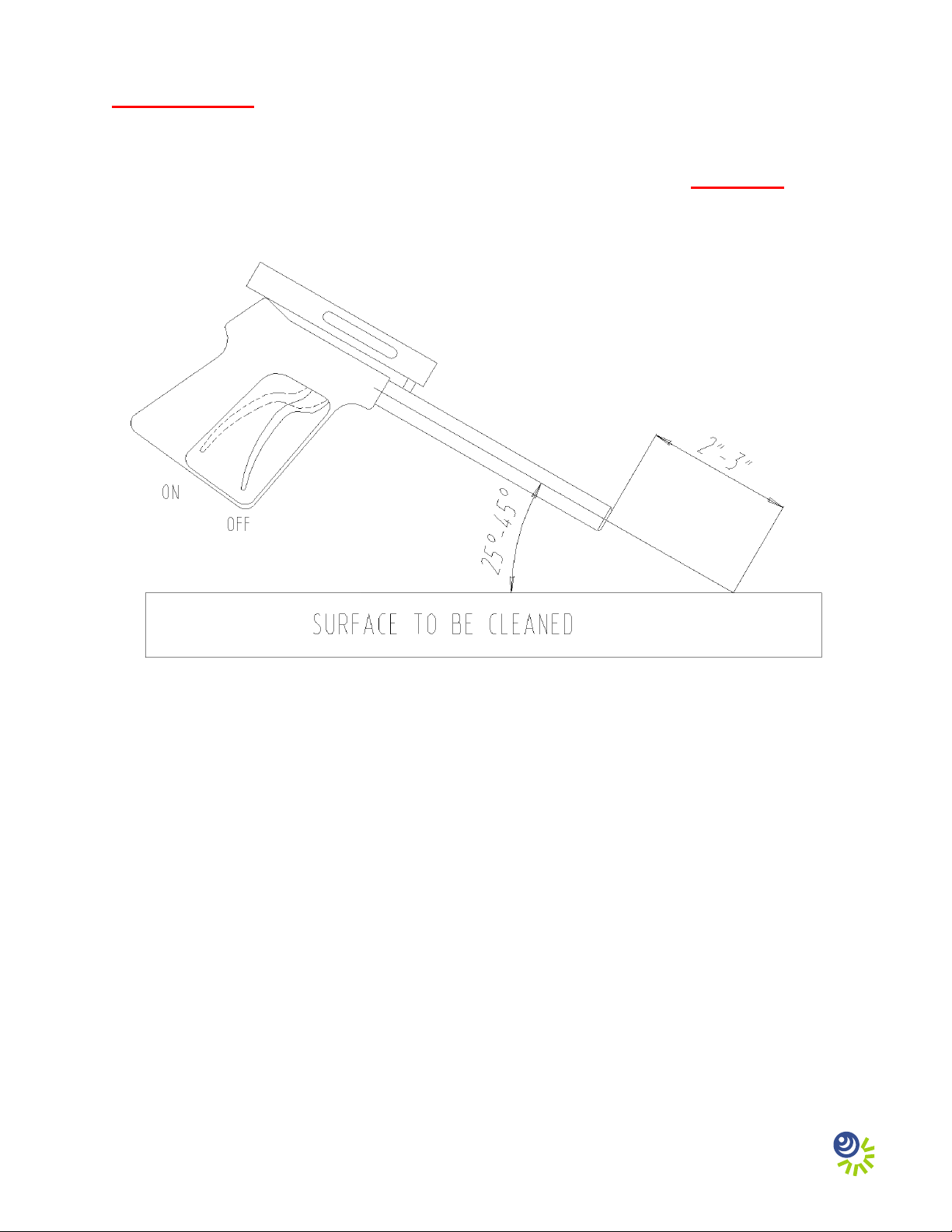
gun trigger to the open or “ON” position (Figure 19) while under water. Revert back to step
1 of the operating instructions when the replacement diver is ready to continue cleaning.
6. Ensure that the gun is submerged any time the engine and pressure pump are operating.
Adjusting the CaviBlaster®system for maximum performance:
1. If using a calibration pressure gauge situated between the pressure hose and the CaviBlaster®
gun, the water pressure should be 2,200-psi with the gun submerged and the gun trigger in
the open or “ON” position. The pressure is adjusted by turning the nuts on the end of the
pressure-regulating unloader (Figure 20). This adjustment increases or decreases the flow of
water through the bypass hose when the CaviBlaster®gun trigger is in the open or “on”
position. The flow of water through the bypass hose, in turn, determines the flow of water
through the pressure hose and the gun. Less flow through the bypass hose means more flow
through the gun which translates to higher velocity and pressure. There should always be a
trickle of water through the bypass when the gun trigger is in the open or “ON” position. This
ensures that the bypass will open without a pressure shock wave damaging the pump when
the gun trigger is released to the closed position.
2. If using a pressure gauge located on the
CaviBlaster®power unit, the water pressure
will need to be higher to account for sidewall
friction loss in the pressure hose. The pressure
at the pump should be 2,200-psi plus 0.75-psi
per foot of pressure hose. For example, if using
the CaviBlaster®with 100 feet of pressure
hose, the pressure gauge located next to the
pump should indicate 2,275-psi. Pressure
adjustments are made in the same manner as
described above. There should always be a
trickle of water through the bypass when the
gun trigger is in the open or “ON” position.
Figure 20
3. If adjusting the CaviBlaster®without a pressure gauge, close the pressure-regulating
unloader until there is just a trickle of water (less than ¼ gallon per minute) coming out of
the bypass with the gun trigger in the open or “ON” position.
Shutting down the CaviBlaster®power unit:
1. Adjust engine RPM to “MIN” (Figure 18).
2. Shut off the engine by turning the key to the “OFF” position (Figure 16).

8
3. Stop the feed pump by moving the feed pump switch to the “OFF”position (Figure 13).
4. Squeeze the gun trigger to the open or “ON” position (Figure 19) to release the water
pressure remaining in the hose(s) while the gun is submerged.
5. It is now safe to remove the gun from the water.
6. Flush the system and rinse the power unit with fresh water at the end of the day.
Maintenance of the CaviBlaster®unit:
1. Empty and clean the inline strainer every day.
2. Check the oil level and consistency in the engine and pressure pump every day.
3. Flush the system and rinse the power unit with fresh water after each days use.
4. Inspect the pump drive belt every week and replace the belt when cracking appears.
5. Change the engine oil after the first month or 20 hours and every six months or 100 hours
thereafter. Replace the oil filter every 200 hours. Use SAE 10W-30 oil for general all-
temperature use.
6. Clean the air cleaner cover, filter elements and base every three months or 50 hours. Replace
the paper filter element every twelve months or 300 hours or if damaged or excessively dirty.
7. Change the oil in the pressure pump after the first 50 hours and every 500 hours thereafter.
Use single-weight lubricating oil (SAE 30 weight non-detergent)
8. Change the spring for the gun trigger every 12 months or less if required.
Summarizing the operating instructions:
1. Inspect the system for damage. Clean the inlet strainer. Check oil/fuel levels.
2. Attach all hoses to the unit and connect the feed pump electrical cable.
3. Start the feed pump or alternate water supply and ensure that the system is primed.
4. Attach the gun to the pressure hose.
5. Make sure that the diver is ready to work and that the gun is submerged in the water.
6. Apply hearing protection, start the engine and adjust the throttle to “MAX.”
7. Activate the cleaning cavitation stream by squeezing the gun trigger to open or “on.”
8. Proceed with cleaning.
9. Shut down the engine.

9
10. Stop the feed pump.
11. Release pressure from the hose(s) by squeezing the gun trigger to the open or “ON”
position while under water.
12. Remove the gun from the water.
13. Flush the system and rinse the outside of the power unit with fresh water.
Trouble shooting instructions:
WARNING
While the CaviBlaster®system is very safe, operators should exercise care when using
the equipment. The cavitation “flame” can be safely passed over the operators’ skin at
normal operating distances of 2” – 3” from the tip of the nozzle. However, at very close
distances (typically less than 1”) both nozzles are capable of causing harm to the
operator, particularly in the initial instant that the system is activated. For that reason,
operators should exercise caution when operating the gun with the nozzles in close
proximity to the body. The operators should also ensure that the reverse-thrust
nozzle guard is secured in the correct position prior to operating the gun.
The operators of the CaviBlaster®system should always wear neoprene or heavy rubber
gloves to provide protection to the hands and, in particular, to the nails. The gloves will
absorb most of the energy produced by bursting cavitation bubbles and prevent the
cavitation bubbles from contacting the operators’ hands. The gloves will also protect
operators’ hands from the initial shockwave when the gun is activated.
Serious harm and injury may result from the misuse of CaviBlaster®system
equipment or improperly selected fittings, hoses or attachments. All components of
the system should be checked against the manufacturers’ instructions to ensure that they
are compatible with the pressures being used and of the correct thread type and pressure
rating for the intended service. Refer to these Operating Instructions and to the engine
and pressure pump manufacturers’ operation manuals for instructions or call CaviDyne,
LLC at (352) 275-5319 with any questions.

Other Caviblaster Pressure Washer manuals
Popular Pressure Washer manuals by other brands

ERRECOM
ERRECOM VP1050.01 quick start guide

Campbell Hausfeld
Campbell Hausfeld PW2002 product manual

Parkside
Parkside PWB 18 A1 Translation of the original instructions

SNOWJOE
SNOWJOE SUNJOE SPX3000-XT Operator's manual

Black & Decker
Black & Decker BEPW1600 Original instructions

Daewoo
Daewoo DAX140-2100G user manual