Installation Instructions
for CL400 ADA Magnetic
Bi-Parting Passage
(Magnetic Latching)
Handles
Before you Start:
1. These handles have been manufactured to specifications which cannot be altered by the installer.
These include:
a Handle type: the CL400 ADA handle is available in Passage, Privacy and Bi-Parting versions.
You have purchased the Bi-Parting Passage (Magnetic Latching) version.
b Configuration: the Passage handle configurations include; Passage Magnetic Latching and
Passage Non Latching.
c Door thickness range: There are four different door thickness ranges: 34-40mm, 40-46mm,
46-52mm and 52-58mm (1-3/8” to 1-9/16”, 1-5/8” to 1-3/4”, 1-13/16” to 2” and 2-1/16” to 2-1/4”).
Handles for thicker doors are available on request.
Refer to the information printed on the Side Handle and Chassis boxes to ensure you have
purchased the handles with the correct specifications for your situation. If the specifications are
incorrect you will need to exchange the handles.
2. Component drawings have been provided. Please familiarise yourself with the components and check
the package to ensure nothing is missing.
3. To ensure the handles latch accurately, it is essential that both doors are adjusted for height and are
parallel with each other when closed before installing the handles.
4. The CL400 is a metric handle. Accurate measurements are shown in millimetres. Conversions to
inches are approximate.
5. NZS4121:2001: To comply with NZS4121:2001 the centre of the handles should be positioned between
900mm and 1200mm (1000mm optimal) above finished floor level. There must be a minimum clear
walk through of 760mm (Aust. 850mm). There must be a 45mm clear space from edge of pull handle
to door jamb when the doors are fully open. Consult local standards for guidelines relating to the
specific project.
USA ADA (American Disabilities Act) Guidelines: Handle should be positioned between 34 - 48”
above finished floor level. Allow a minimum of four inches for the protrusion of the door in the
open position. This can be achieved by using track stops or blocking in the back of the pocket.
Consult local standards for guidelines relating to the specific project.
4
PAGE
2
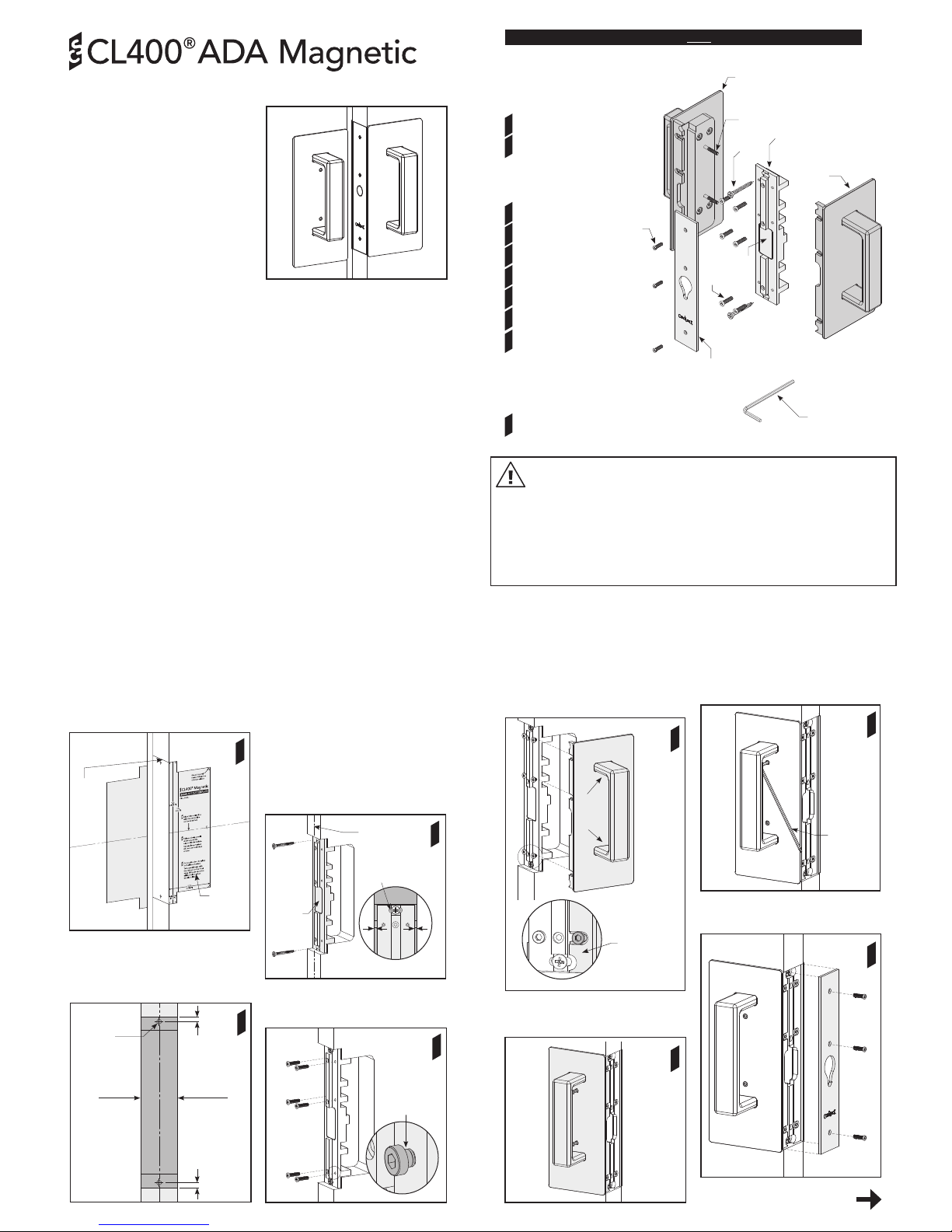
Component Drawings - Bi-Parting Mate
IMPORTANT: Install THIS handle FIRST
PAGE
a
b
c
d
e
f
g
h
Bi-Parting Side Handle (Left)
Bi-Parting Side Handle (Right)
i (2)
b
c
d
a
e
f (2)
g (6)
h (3)
Bi-Parting Side Handle Box
Bi-Parting Face Plate
Bi-Parting Chassis
Magnet
Chassis Mounting Screws (2)
Side Handle to Chassis Screws (6)
Face Plate Screws (3)
Handle Joining Screws (2)
Bi-Parting Chassis Box
Door Preparation Fitting the Bi-Parting Mate Fitting the Bi-Parting Mate
3
PAGE
1. Mark a line on the face of the doors where
the centre of the handles are to be positioned.
Align the centre line on the door cut out
template with the centre line on the door.
Follow the instructions on the template.
Repeat cut out for both doors.
Door faceDoor face
Door
cut out
template
Transfer
lines
across
front
edge of
doors
2. Mark two holes in the centre of the door
thickness in the positions shown. Using these
marks, drill two 2.5mm (3/32”) diameter holes
to a depth of 35mm (1-3/8”).
Repeat holes for both doors.
1
Chassis
mounting
screws
Centre of door
thickness
3
3. The Bi-Parting chassis contains a
strong magnet. Read the warning on
page 2 before continuing.
Remove the Bi-Parting chassis from its
packaging. Remove the face plate screw
and face plate from the chassis.
Align the chassis with the centre of the door
thickness. Screw the chassis to the door (using
the two chassis mounting screws) through
the slotted holes at the top and bottom of the
chassis. DO NOT fully tighten the screws.
Realign the chassis with the centre of the
door thickness. When happy with the chassis
position, fully tighten the screws.
3mm (1/8”) gap
under head
Side handle
to chassis
screws
4
4. Fit the 6x side handle to chassis screws.
Leave a 3mm gap (1/8”) between the underside
of the screw head and the chassis.
Go to page 5 (overleaf)
Magnet
5. Select the Bi-Parting side handle that has
no visible fasteners (see diagram 5). Fit it to
the chassis by sliding the front flange of the
handle under the heads of the 3x side handle
to chassis screws. Tighten the screws.
5
6
7
8
6. Fit the remaining Bi-Parting side handle to
the chassis and tighten the 3x side handle to
chassis screws.
8. Fit the Bi-Parting face plate to the chassis
using the 3x face plate screws.
Face
plate
screws
Correct alignment
✓
==
Slotted hole
i
jCL400 Allen Key j
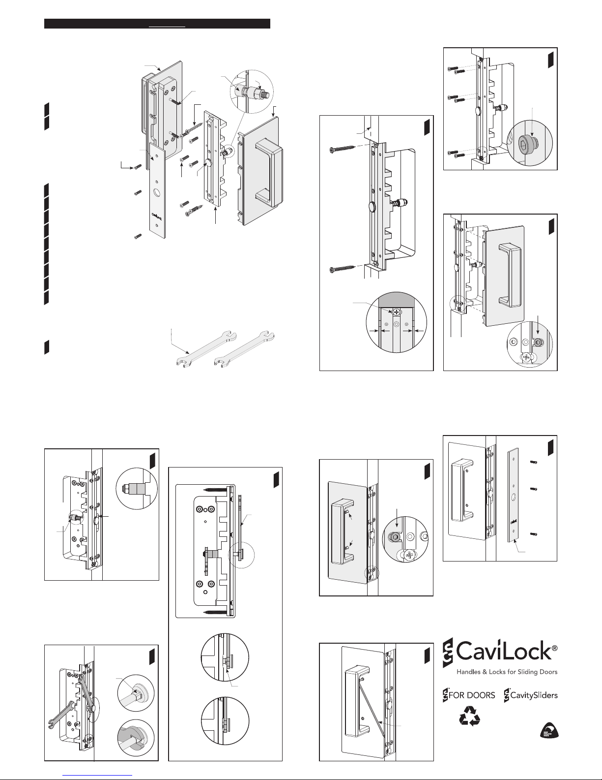
Tools (contained in Bi-Parting Chassis Box)
WARNING: THE BI-PARTING CHASSIS CONTAINS A STRONG MAGNET
IRON FILINGS - Magnets will attract shavings from iron or ferrous metals which may be hard to
remove. Keep magnets a safe distance away from these materials.
DANGER FOR CHILDREN - Magnets may cause serious injury if swallowed. Keep out of reach of children.
CRUSHING, BLISTERS AND CUTS - Fingers may become caught between magnets resulting in crushing,
blisters or cuts.
BREAKING OR CHIPPING - It is possible that magnets could chip or shatter on contact with other hard
materials, resulting in chips flying off at high speed into someone’s eye. Chips can also be very sharp - treat
them as you would broken glass.
MAGNETICALLY SENSITIVE ITEMS - Keep a safe distance between the magnet and all objects that can
be damaged by magnetism (e.g. mechanical watches, pacemakers, cell phones etc.).
DISPOSAL - Magnets should be disposed of carefully and in accordance with your local regulations.
Bi-Parting
face plate
Front flange
CL400
Allen key
5mm
(13/64”)
5mm
(13/64”)
Ø 2.5mm
(3/32”)
2
Door
thickness
1
PAGE
7. Use the ball end of the CL400 Allen
key to tighten the 2x handle joining
screws.
Use the other end of the Allen key to
firmly tighten the screws.
M3.5
handle
joining
screws
No
visible
screws
here
Straight handle option shown.