CB BILANCIAI SEL700 Operating and maintenance manual

USE AND WARNING INSTRUCTIONS
Revision 00 - Edition 12/2020
TRANSLATION OF THE ORIGINAL INSTRUCTIONS
SEL700 WEIGHING SYSTEM
Serial number -
Client -
Year of manufacture 2020
Soc. Coop. Bilanciai Campogalliano
Campogalliano (MO) - 41011 - Via S.Ferrari, 16
Tel. +39 059.893611

0-2
TABLE OF CONTENTS
Use and warning instructions
TABLE OF CONTENTS
INTRODUCTION
All rights reserved. No part of this publication may be reproduced, distributed, translated into other languages, or transmitted by
any electronic or mechanical means, including photocopying, recording, or any other storage and retrieval systems, for purposes
other than the purchaser’s exclusive personal use, without the manufacturer’s express written approval.
The Manufacturer shall not be held liable under any circumstances for the consequences resulting from any incorrect operations
by the user.
PUBLISHER’S NOTE
This documentation is expressly intended for technicians; therefore, some information that can be easily drawn from reading the
texts and examining the drawings may not have been specified further.
The Publisher shall not be held liable under any circumstances for the information and data contained in this manual, all of which
was provided, checked and approved by the Manufacturer during verification.
The Publisher shall not be held liable under any circumstances for the consequences resulting from any incorrect operations by
the user.
GENERAL REMARKS
All operating and maintenance instructions, as well as recommendations described in this manual, must be complied with. For
best results, the manufacturer recommends that cleaning and maintenance be performed regularly to keep the system in the best
working order.
Training the personnel in charge of the machine to properly use and service it, as well as checking compliance with the operating
procedures and all the safety standards set forth in this manual is particularly important.
REVISION INDEX
REV. PUBLICATION
NOTES FINAL PAGE NO. DATE
00 First version - 11/2020
01
02
COPYRIGHT
© 2020 SOCIETÀ COOPERATIVA BILANCIAI

03
TABLE OF CONTENTS
SEL 700
TABLE OF CONTENTS
1. IDENTIFICATION .............................................................................................................................11
1.1 Manufacturer identication..............................................................................................................................................................................1-1
1.2 Machine identication........................................................................................................................................................................................1-1
1.3 Identication plate................................................................................................................................................................................................1-1
1.4 EC Declaration of Conformity ..........................................................................................................................................................................1-2
1.5 Reference directives .............................................................................................................................................................................................1-3
2. PRELIMINARY INFORMATION ........................................................................................................23
2.1 Recipients..................................................................................................................................................................................................................2-3
2.2 Supply and storage...............................................................................................................................................................................................2-3
2.3 Updates......................................................................................................................................................................................................................2-3
2.4 Language..................................................................................................................................................................................................................2-3
2.5 Operators ..................................................................................................................................................................................................................2-4
2.6 Symbols used within the manual ..................................................................................................................................................................2-5
2.7 Glossary......................................................................................................................................................................................................................2-6
2.8 Personal protective equipment ...................................................................................................................................................................2-11
2.9 User safety area ................................................................................................................................................................................................... 2-12
2.10 Warranty................................................................................................................................................................................................................. 2-13
3. SAFETY DEVICES.............................................................................................................................33
3.1 Safety warnings......................................................................................................................................................................................................3-3
3.2 Safety devices..........................................................................................................................................................................................................3-5
3.2.1 Fixed and shaped guards..........................................................................................................................................................................................3-6
3.2.2 Emergency pushbutton.............................................................................................................................................................................................3-6
3.2.3 Tower stack lights .........................................................................................................................................................................................................3-7
3.2.4 Buzzer.................................................................................................................................................................................................................................3-7
3.2.5 Power switch (with padlock)...................................................................................................................................................................................3-7
3.3 Noise ...........................................................................................................................................................................................................................3-8
3.4 Vibrations ..................................................................................................................................................................................................................3-8
3.5 Electromagnetic compatibility........................................................................................................................................................................3-8
3.6 Residual risks............................................................................................................................................................................................................3-9
3.7 Safety pictograms applied to the machine ............................................................................................................................................ 3-10

0-4
TABLE OF CONTENTS
Use and warning instructions
TABLE OF CONTENTS
4. MACHINE DESCRIPTION .................................................................................................................43
4.1 Proper intended use.............................................................................................................................................................................................4-3
4.2 Reasonably foreseeable misuse......................................................................................................................................................................4-3
4.3 Obligations and prohibitions...........................................................................................................................................................................4-4
4.3.1 Users’obligations..........................................................................................................................................................................................................4-4
4.3.2 Operators’ obligations.................................................................................................................................................................................................4-4
4.3.3 Operators’ prohibitions...............................................................................................................................................................................................4-4
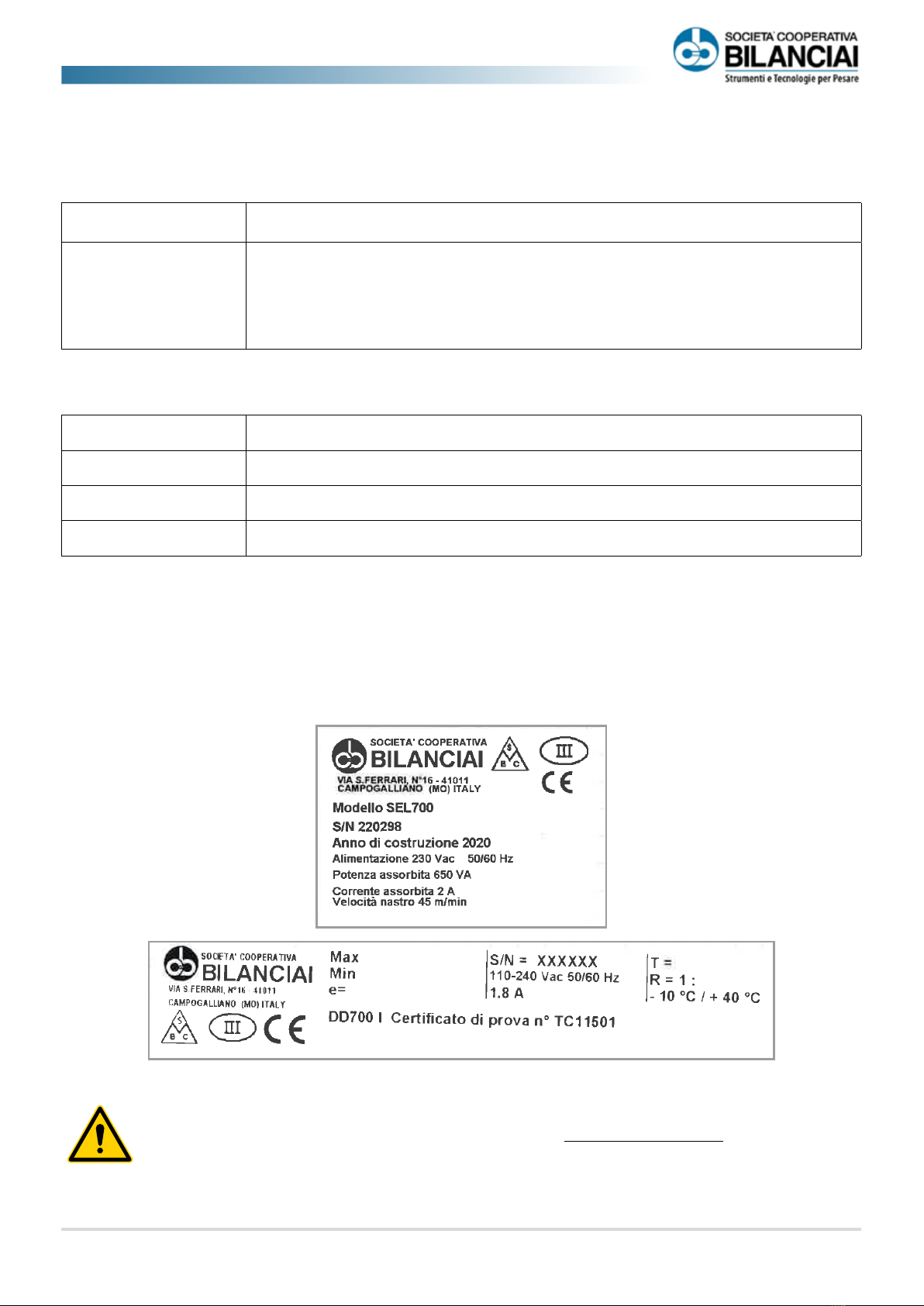
4.4 Technical data.........................................................................................................................................................................................................4-5
4.5 Layout measurements ........................................................................................................................................................................................4-6
4.6 Main components.................................................................................................................................................................................................4-7
4.7 Operating cycle......................................................................................................................................................................................................4-8
5. TRANSPORT AND INSTALLATION...................................................................................................53
5.1 Packaging..................................................................................................................................................................................................................5-4
5.1.1 Packaging removal.......................................................................................................................................................................................................5-4
5.1.2 Disposal of packaging ................................................................................................................................................................................................5-4
5.2 Transport and handling......................................................................................................................................................................................5-5
5.2.1 Unit and weight division table ...............................................................................................................................................................................5-5
5.2.2 Transport operations...................................................................................................................................................................................................5-5
5.3 Installation................................................................................................................................................................................................................5-7
5.3.1 Set-ups to be provided by the customer...........................................................................................................................................................5-7
5.3.2 Permitted environmental conditions...................................................................................................................................................................5-7
5.3.3 Installation place...........................................................................................................................................................................................................5-8
5.3.4 Positioning......................................................................................................................................................................................................................5-9
5.3.5 Installation .......................................................................................................................................................................................................................5-9
5.3.6 Levelling.........................................................................................................................................................................................................................5-10
5.3.7 SEL700 + 4 I/O terminal installation..................................................................................................................................................................5-11
5.3.7.1 Scale parameters (path: \\ Setup\ Scale\ Congurations\ General\ )................................................................................5-12
5.3.7.2 Weighing management parameters (path:\\ Setup \ Customisations \ Work modes \ Operation \ Single weigh-
ing \ Standard\)..........................................................................................................................................................................................5-12
5.3.7.3 Parameters for input contacts (path: \\ Setup\ Customisations\ Outputs\ Inputs) ....................................................5-14
5.3.7.4 Parameters for output contacts (path: \\ Setup\ Customisations\ Outputs\ Output) ...............................................5-16
5.3.7.5 Parameters for analogue output (path: \\ Setup\ Customisations\ Outputs\ Analogue Output\) ......................5-17
5.3.7.6 Default programming .............................................................................................................................................................................5-17
5.3.8 Data available from user menu ...........................................................................................................................................................................5-19
5.3.8.1 How to calculate the piece time to associate to the product...............................................................................................5-22
5.3.9 Main page....................................................................................................................................................................................................................5-23

05
TABLE OF CONTENTS
SEL 700
TABLE OF CONTENTS
5.3.9.1 Data displayed on main page..............................................................................................................................................................5-23
5.3.9.2 Functions available on the main page (keys and inputs)........................................................................................................5-23
5.3.10 Working page..............................................................................................................................................................................................................5-25
5.3.10.1 Data displayed on work page..............................................................................................................................................................5-25
5.3.10.2 Functions available on the working page (keys and inputs).................................................................................................5-25
5.3.11 Weight printout and transmission to pc (optional)...................................................................................................................................5-26
5.3.11.1 Printer .............................................................................................................................................................................................................5-26
5.3.11.2 Transmission to PC....................................................................................................................................................................................5-26
5.3.11.3 Printed data string ....................................................................................................................................................................................5-26
5.3.11.4 Additional transmission parameters.................................................................................................................................................5-28
5.3.11.5 Notes on the composition of the string..........................................................................................................................................5-28
5.3.11.6 String of printed data of this terminal..............................................................................................................................................5-28
5.3.11.7 ACK/NAK protocol.....................................................................................................................................................................................5-28
5.3.11.8 Calculating the checksum.....................................................................................................................................................................5-29
5.3.12 Important notes and limits of the terminal ...................................................................................................................................................5-30
5.3.13 Example of new production start.......................................................................................................................................................................5-30
5.3.14 Error messages and warnings..............................................................................................................................................................................5-31
5.4 Connections.......................................................................................................................................................................................................... 5-33
5.4.1 Electrical connection................................................................................................................................................................................................5-33
6. CONTROLS AND HOW TO USE THEM..............................................................................................63
6.1 Operator workstation ..........................................................................................................................................................................................6-3
6.2 Command pushbutton panel..........................................................................................................................................................................6-4
6.3 Operator panel .......................................................................................................................................................................................................6-5
6.4 Operational procedures......................................................................................................................................................................................6-6
6.4.1 Preliminary checks .......................................................................................................................................................................................................6-6
6.4.2 Machine setup operations........................................................................................................................................................................................6-6
6.4.3 Start up..............................................................................................................................................................................................................................6-6
6.4.4 Restart after an emergency stop ...........................................................................................................................................................................6-7
6.4.5 Restart after alarm intervention.............................................................................................................................................................................6-7
6.4.6 Shutdown.........................................................................................................................................................................................................................6-7

0-6
TABLE OF CONTENTS
Use and warning instructions
TABLE OF CONTENTS
7. MAINTENANCE................................................................................................................................73
7.1 Safety warnings......................................................................................................................................................................................................7-4
7.2 Routine maintenance..........................................................................................................................................................................................7-5
7.2.1 Checks and inspections .............................................................................................................................................................................................7-5
7.2.1.1 Replacing the conveyor belt...................................................................................................................................................................7-6
7.2.1.2 Conveyor belt tensioning .........................................................................................................................................................................7-8
7.2.1.3 How to check the weighing system ....................................................................................................................................................7-9
7.2.2 Cleaning.........................................................................................................................................................................................................................7-10
7.2.2.1 Cleaning conveyor belts.........................................................................................................................................................................7-10
7.2.2.2 Cleaning photocells .................................................................................................................................................................................7-11
7.2.2.3 Cleaning the compressed air lter (main machine) ..................................................................................................................7-11
7.3 Extraordinary maintenance ...........................................................................................................................................................................7-12
8. DECOMMISSIONING AND DISPOSAL .............................................................................................83
8.1 Disposal......................................................................................................................................................................................................................8-3
9. ANNEXES .........................................................................................................................................93

11
SEL 700
CHAPTER 1 - Identication
1. IDENTIFICATION
1.1 Manufacturer identication
Manufacturer SOCIETÀ COOPERATIVA BILANCIAI
Address
Via S.Ferrari, 16
Campogalliano (MO) - Italy
Tel. +39 059.893611
1.2 Machine identication
Machine SEL 700
Serial number -
Client -
Year of manufacture 2020
1.3 Identication plate
The machine identification details to be submitted to SOCIETÀ COOPERATIVA BILANCIAI in case of need are shown on the
nameplate.
CAUTION!
Removing the EC nameplate and/or replacing it with other plates IS STRICTLY FORBIDDEN.
Should the plate be accidentally damaged or removed, the Customer must inform the Manufacturer.

1-2
Use and warning instructions
CHAPTER 1 - Identication
1.4 EC Declaration of Conformity
Dichiarazione di conformità UE
(Allegato II, parte 1, sezione A della Direttiva 2006/42/CE sulle Macchine)
1. Strumento per pesare a funzionamento automatico
TIPO/MODELLO
SEL700
N° di serie
XXXXXX
2.
FABBRICANTE:
SOCIETÀ COOPERATIVA BILANCIAI CAMPOGALLIANO Via S.
Ferrari,16 41011 Campogalliano MO (ITALIA)
3.
La presente dichiarazione di conformità è rilasciata sotto la responsabilità esclusiva del
fabbri-
cante.
4.
Oggetto della dichiarazione: vedi 1.
5.
L'oggetto della dichiarazione di cui sopra è conforme alle pertinenti direttive e normative di armonizzazione
dell'Unione:
- 2014/30/UE (EMC) : Norme EN 61000-6-2:2006, EN 61000-6-4:2007, EN 61000-4-3:2006,
EN 61000-4-4:2014, EN 61000-4-5:2014, EN 61000-4-6:2014, EN 61000-4-11:2004
- 2014/35/UE (LVD):Norme EN 61439-1:2010, EN 60204-1:2006
- 2006/42/CE (MD) : Norma EN 12100:2010
8.
Informazioni aggiuntive:
nell'utilizzo devono essere rispettate tutte le istruzioni riportate nel manuale d'uso a corredo dello
strumen-
to, nonché tutte le norme in materia di sicurezza e prevenzione degli infortuni vigenti nel
paese di utilizzo.
Sul prodotto è stata apposta la marcatura CE.
Nel caso in cui lo strumento venga inserito in un impianto, ne è VIETATA la messa in servizio e
l’immissione sul mercato prima che il medesimo impianto, in cui lo strumento è destinato ad essere in-
corporato, sia messo in condizioni di sicurezza e dichiarato, in base alla prescritte valutazioni di conformi-
tà da svolgersi sotto la responsabilità del fabbricante dell’impianto, conforme ai requisiti di sicurezza ed ai
requisiti essenziali previsti dalle pertinenti normative legislative e regolamentari, specie di natura comuni-
taria, applicabili in materia in base ai paesi di destinazione
Si dichiara inoltre che la persona autorizzata a costituire il fascicolo tecnico della macchina è:
SOCIETÀ COOPERATIVA BILANCIAI CAMPOGALLIANO
Firmato a nome e per conto del fabbricante: Luogo e Data: [ L u o g o ]
XX / XX / XXXX

13
SEL 700
CHAPTER 1 - Identication
1.5 Reference directives
The machine supplied by SOCIETÀ COOPERATIVA BILANCIAI does not fall into any of the machinery categories listed in Annex IV of
the Directive; therefore, with a view to proving its compliance with the provisions of this directive, SOCIETÀ COOPERATIVA BILANCIAI
applies the conformity assessment procedure with internal checks on the manufacture of machinery, provided for in Annex VIII.
To certify machine compliance with the Machinery Directive provisions, before placing the machine on the market,
SOCIETÀ COOPERATIVA BILANCIAI carried out a risk assessment in order to check compliance with the essential health and safety
requirements of the Directive, as well as the tests and checks set out in the applied reference standards.
The technical construction file was drawn up in accordance with the provisions of Annex VII of Directive 2006/42/EC and can be
checked by supervisory bodies upon reasoned request, as provided for by current relevant legislation.
Then, the machine will be placed on the market by SOCIETÀ COOPERATIVA BILANCIAI
CE marking
EC Declaration of Conformity
Instruction and warning manual (Documentation drawn up as provided for under 1.7.4 of the Machinery Directive 2006/42/EC)
please also note that the machine was designed in accordance with the following Directives:
2006/42/EC Machinery Directive
2014/30/EU Electromagnetic Compatibility (EMC) Directive
2014/35/EU Low Voltage Directive
And that the following harmonised standards have been applied:
UNI EN ISO 12100:2010 Safety of machinery - General principles for design - Risk assessment and risk reduction
EN 61000-4-11:2004 Electromagnetic compatibility (EMC) - Testing and measurement techniques - Voltage dips,
short interruptions and voltage variations immunity tests
EN 61000-4-6:2014 Electromagnetic compatibility (EMC) - Testing and measurement techniques - Immunity to
conducted disturbances, induced by radio-frequency elds
EN 61000-4-5:2014 Electromagnetic compatibility (EMC) -Testing and measurement techniques - Surge immunity
test
EN 61000-4-4:2014
EN 61000-4-3:2006 Electromagnetic compatibility (EMC) - Testing and measurement techniques - Radiated, radio-
frequency, electromagnetic eld immunity test
EN 61000-6-4:2007 Electromagnetic compatibility (EMC) - Emission standard for industrial environments
EN 61000-6-2:2006 Electromagnetic compatibility (EMC) - Immunity for industrial environments
EN 60204-1:2006 Safety of machinery
EN 61439-1:2010 Low-voltage switchgear and control gear assemblies
CAUTION!
The operating conditions of the electronic terminal for weighing instruments are regulated by the standards in
force in the country of use. Any use which does not comply with these standards is prohibited.

1-4
Use and warning instructions
CHAPTER 1 - Identication
PAGE LEFT INTENTIONALLY BLANK

2-1
SEL 700
CHAPTER 2 - Preliminary information
Chapter 2
PRELIMINARY INFORMATION

2-2
Use and warning instructions
CHAPTER 2 - Preliminary information
PAGE LEFT INTENTIONALLY BLANK

2-3
SEL 700
CHAPTER 2 - Preliminary information
2. PRELIMINARY INFORMATION
2.1 Recipients
The manual is intended for operators in charge of using and managing the machine throughout its service life.
It deals with any subjects related to proper use of the machine, in order to keep its operating and quality features unchanged over
time. All information and warnings about how to properly and safely use the machine are also provided.
The manual, like the EC certificate of conformity, is an integral part of the product and must always accompany it whenever it is
transferred or resold. The user is required to keep the documentation intact so that it can be referred to throughout the service life
of the machine.
2.2 Supply and storage
The manual is provided in both hard and soft copies.
All additional documentation (pneumatic and electrical diagrams, sub-supplier manuals) is attached to this manual.
Keep this manual with the machine, so that it can be easily referred to by the operator.
The manual is an integral part for safety purposes, therefore:
• it must be kept intact (in all its parts). If it is lost or damaged, a copy must be requested immediately.
• must follow the machine until demolition (even in the case of transfer, sale, leasing, rental, etc.);
• The attached manuals are an integral part of this documentation, and the same recommendations/requirements set out in
this manual apply to them.
The Manufacturer shall not be held liable for any misuse of the machine and/or damage caused as a result of operations not
provided for in the technical documentation.
IMPORTANT!
• All the technical information contained in this manual is the exclusive property of the Manufacturer and
must be considered as being of a reserved nature.
• The reproduction and disclosure, even partial, of this manual on paper, digital support or on the WEB
without written consent from the Manufacturer is prohibited.
2.3 Updates
If the machine requires functional changes or replacements, the revision or updating of the manual shall be the Manufacturer’s
responsibility. The Manufacturer undertakes to deliver any manual update.
If any changes are made to this document by the Manufacturer, the user shall ensure that only the updated versions of the manual
are actually available at the points of use.
2.4 Language
The original manual was drawn up in Italian.
Any translations into additional languages shall be done from the original instructions.
The Manufacturer is responsible for the information contained in the original instructions; translations into different languages
cannot be fully verified, therefore if any inconsistencies are found, please refer to the original text, or contact our Technical
Documentation Department.

2-4
Use and warning instructions
CHAPTER 2 - Preliminary information
2.5 Operators
In order to establish with certainty what the skills and qualifications of the operators assigned to the various tasks (start-up, cleaning,
routine maintenance) are, please refer to the following table:
Job description Denition
Machine operator
Personnel entrusted with the operational management of the machine - switch-on, start-up, shutdown, proper
product feeding.
Note: not allowed to perform any maintenance.
Machine programmer
Personnel entrusted with machine programming, a task that does not entail any hazards for persons or property.
Special carefulness is required from the person performing this task, as some programming operations can damage
previously memorised data. The person must also be familiar with the company’s productive organisation so as to
enter the appropriate information.
Lifting and handling
equipment operator
operator authorised to use equipment for lifting and handling materials and machines (strictly following the
Manufacturer’s instructions) in accordance with the laws in force in the machine user’s country.
Maintenance techni-
cian
Mechanic
Qualied technician who is entrusted with checking mechanical components for cleanliness and proper
preservation as well as adjustment and maintenance conditions.
Note: he/she is not authorised to operate on live electrical systems (if any).
Maintenance techni-
cian
Electricity
Qualied technician who is entrusted with managing maintenance work and any electrical malfunctions, in
addition to being able to conduct work in the control panel if needed.
After-sales service Skilled technician who deals with all complex adjustments, maintenance, repairs, or other operations to be carried
out in particular conditions.
The qualifications shown in the table on this page necessarily fall within the “trained person” category.
Type Denition
Trained person
One who has been informed, instructed and trained in the job, and is acquainted with any dangers resulting from
misuse. The person is also aware of the importance of safety devices, accident-prevention regulations and safe
working conditions.

2-5
SEL 700
CHAPTER 2 - Preliminary information
2.6 Symbols used within the manual
In order to establish with certainty what the skills and qualifications of the operators assigned to the various tasks (start-up, cleaning,
routine maintenance) are, please refer to the following table:
Symbol Term Denition
CAUTION! Identies situations that could lead to product damage if not adhered to.
CAUTION! Identies situations that could result in personal injury or adversely aect machine performance if not
properly adhered to.
DANGER! Identies situations that could result in severe injury or death if not adhered to.
IMPORTANT! Identies particularly important information in the manual that is not related to safety.
PROHIBITION! Identies prohibited situations
RESPECT
THE ENVIRON-
MENT!
Identies information and precautions on how to dispose of contaminated waste and respect the
environment.

2-6
Use and warning instructions
CHAPTER 2 - Preliminary information
2.7 Glossary
Technical terms or with a meaning other than the common are used in the manuals.
The used terms and abbreviations are explained below:
Term Denition
Up-down
function that allows an automatic device to be activated in order to mechanically isolate the scale plate - product
system when this is in the weighing position for the time that weighing lasts (static), thus enabling it to weigh
products that are longer than the scale belt.
Autoreset
the scale’s automatic periodical resetting system. It can only be enabled during an automatic weighing phase.
The scale is automatically reset at established intervals, and only when the plate is unloaded, guaranteeing that
it will not be loaded automatically with a weight during the resetting procedure. The autozero managing logic is
described in the domain rules.
Resetting process with which the weight indication is returned to zero, annulling the load bearing on the cell, within the
preset limits.
Barcode data structure formed by xed and variable elds of the process able to be printed on the label. Each barcode must
therefore be able to indicate the data of the process in relation to which it is created
BcRead
indicates the format of a barcode that the system can read during the process (by means of a scanner) in order to
automatically modify a sub-group of data pertaining to the current process.
Each bcread must be described by the sequence of elds it contains and unambiguously identied within the
sequence of characters of the barcode itself.
Scale
component that processes the data from the load cell and that provides weighing functions (obtainment of a
gross weight value and calculation of the relative entities derived).
It also memorises a group of information representing the calibration data and which is the result of the calibration
processes.
Braid
component that processes the data from the load cell and that provides weighing functions (obtainment of a
gross weight value and calculation of the relative entities derived).
It also memorises a group of information representing the calibration data and which is the result of the calibration
processes.
Sampling (1) (also
calibration)
process with which a bond is established between the intensity of the signal leaving the load cell and the weight
bearing on it.
Sampling can be:
• linear: the bond between the signal and weight is considered to be linear and thus described by means of
the equation of a straight line;
• non-linear: the bond between the signal and weight is considered to be describable by means of a second-
degree equation.
Sampling (2) group of information that describes the bond obtained during calibration.
Zero sampling process by which the load bearing on the cell is annulled the moment in which it is activated, thus modifying the
sampling data.
Center Zero denes a weight range around the zero mark between ± 1/4 of a division.
Connector plug or socket for connecting the terminal to the external equipment.

2-7
SEL 700
CHAPTER 2 - Preliminary information
Term Denition
Counters
they are global consecutives associated with the equipment.
Some express information which, although global, are modied during the process and therefore need to be
handled according to the pipeline logic of the process itself (namely, information that must be historicised so that
it can be recovered according to the instant in which it was produced).
Some pertain to the actual system and cannot be reset during the life of the machine. Others, as they pertain to
parts that are liable to be replaced, must include a resetting mechanism.
Default value provided by the data memory in the absence of an entry via the keyboard. The data entered by the
manufacturer are retrieved as default values.
Key-in press the command that needs to be activated or the character to be retrieved on the display, using the keyboard.
Display lit screen on which the numeric data and symbols transmitted by the system appear, so that they can be
immediately consulted.
Division appreciable minimum weight variation.
Zero division this is the division (1/2 before and 1/2 after) spanning the scale resetting value.
Multiple divisions automatic system for changing the division depending on the weighed load. It works when the scale is either
loading or unloading.
Multiple extensions automatic system for changing the weighing range in systems with several ranges and dierent maximum
capacities. Once the scale has been loaded, return to zero occurs within the last range switched.
Label
group of graphic elements that express the forms and data of the process in a printable form.
The following elements can be included in a label:
• xed texts
• variable texts
• barcodes
• images
• lines
• rectangles
The sequence in which the elements are transmitted to the printer is signicant, since, in the case of overlapping,
each element overwrites the previously transmitted one which partially or totally occupies the same area.
Labelling
process whereby the label is applied to the product and totalising of the same within the process is performed.
If the product label (or printer) is not present, the process will deal with totalising alone. If the piece is not to be
totalized (namely rejected), the process is annulled.
Full scale this is the maximum weighing capacity of the instrument, which does not necessarily coincide with the max.
structural capacity of the weighing platform.
Host Remote system that connects to the Weighing-pricing system in order to handle and program it.
Image graphic element that must be able to be stored in the system so that it can be displayed and printed.
Interface group of circuits and channels that connect the terminal with the external devices to which it is linked.
IP xx
protection degree for casings and enclosures containing electrical or electronic components. The IP rating
indicates the protection class of electronic equipment against solid matters (the rst number) and liquid (the
second number).
Process (1) status of the system in which, if appropriately stimulated (cell loading, photocell obscuring, command from the
interface), it is able to process the individual products.

2-8
Use and warning instructions
CHAPTER 2 - Preliminary information
Term Denition
Process (2) weighing, labelling, weight /price data calculation, totalising and possible handling process, the subject of which
is a group of products pertaining to a specic PLU.
Process (3)
group of information that characterises the process of a specic PLU. It consists of the group of data of the PLU in
question with the addition of the following elements:
• the weighing-pricing data of the last product weighed;
• the consecutives linked to the totals.
Traceability lot
group of information that identies and describes a production lot (typically refers to the livestock market) used
to obtain dierent products to process.
The information that identies and describes the traceability lot can be congured as described in the relative
section of the Supplementary Specications.
Mask graphic representation of data, characters or symbols on the display, according to the modes established by the
manufacturer.
Multi-division see “Multiple divisions”.
Multi-extension see “Multiple extensions”.
Operator person who uses the system.This is therefore the person who must have read this manual and who is fully familiar
with the operating controls.
Option the equipment that is not part of the standard supply.
Minimum weighing
operation
corresponds to the interval between 0 (zero) and a pre-established number of divisions. A high relative error can
occur in this zone.
Weighing Process by which the weight bearing on the load cell during the actual process is measured.
Automatic weighing Automatic weight measuring process that does not require the intervention of an operator
Dynamic weighing Automatic weighing process in which weight measurement occurs without stopping the product on the scale
plate.
Manual weighing
Weight measuring process that requires the intervention of an operator. It can activate in automatic mode as soon
as the operator loads a product on the scale plate or in manual mode, when the operator starts up the process
itself.
Static weighing Automatic weighing process in which the product handling system that regulates the way the product is loaded
onto the scale, stops the piece on the scale plate so that the weight can be measured.
Weighing
platform part of the set-up on which the goods are placed for weighing.
PIN pin, rheophore or pole to which the cable connects.
PLC freely programmable electronic component containing the program that controls the machine on which it is
installed.
PLU
acronym of PRICE LOOK UP, or search (identication) unit of the product. It collects all the specic information
about every product that can be processed, or supplies the group of data required to guide the transport, handling,
weighing, labelling and totalising process.
Additional information expressing the PLUs relation with other elements in the system can be associated with
each PLU.
Pole see PIN.

2-9
SEL 700
CHAPTER 2 - Preliminary information
Term Denition
Maximum capacity maximum weighing capacity
Transmission
protocol data encoding and sorting system in a transmission towards an external device.
Stopping position by
a belt
a position (target) must be identied on each belt on a level with which the products stop in order to be subjected
to the process pertaining to that particular belt (stopping while waiting for events, enabling, conrmation from
the user, weighing, labelling).
Weighing range weighing range between the minimum weight and maximum capacity.
Load receiver part of the instrument where the load is positioned for weighing.
Scanner barcode reader
Serialisation data transmission, character by character.
Slot position or housing for the board in the terminal.
Stopped status machine condition in which all the belts are at a standstill or being stopped, and in which they stop as soon as the
pieces in the machine reach the stopped position on the individual belts.
Belt consent status
a belt "is enabled" if the next belt (or the next machine relative to the last belt in the line) is able to accept pieces.
This means that if a belt has not been enabled, a piece in transit on it must stop at the relative stopping
position, or that it cannot start again until its processing status in that position has been completed.
Processing status condition in which the line is to be found that allows the conveying system to accept pieces, move them, weigh
them, label and totalize them. The opposite situation is called "o process”.
Running status machine condition in which the pieces must be able to be moved continuously, in compliance with the
downstream enabling conditions.
Store
reservoir of information, which can contain:
• the code of a process;
• information that guides the process of the specied code (if present) in relation to weighing, handling,
characteristics associated with the process.
String sequence of alphanumerical characters exchanged during a serial transmission between the terminal and external
equipment.
Weighing
instrument measuring instrument that determines the "weight" entity of a body.
Preset tare
Tare value associated with a product (PLU), the origin of which is a known value that is entered in the system. It is
used for calculating the net weight at the time the weight data of a PLU being processed are calculated. Since the
scale that measures the gross weight can have a dierent capacity and division each time, the value of the tare
associated with the PLU must not be rounded-o in any way.
Percentage tare (also
weight drop)
Percentage value that expresses an additional tare element equal to the actual percentage value of the net weight,
which is consequently decreased to a further extent by the tare value thus obtained.
Printhead (single
head, double head)
The printhead consists of a printer and an applicator that can be the air-jet, arm or piston type. An Automatic
weighing-pricing system can have one or two printheads (double head). If there are two heads, they are either
positioned in line or above and below.
Fixed text text element led in the system and unambiguously identied by a numeric code. Each text must belong to a
category (ingredients, products, label texts)

2-10
Use and warning instructions
CHAPTER 2 - Preliminary information
Term Denition
Variable text
(or Variable eld)
data item of each process which can be included in labels, barcodes, reports.
The variable texts include:
• elds of the actual process;
• information bound to the traceability lot currently set in the system;
• general totals.
General total totalising element that sums the values created by processing the individual pieces across the actual process itself.
Data transmission exchange of information between two or more devices via electric cables.
Zero tracking
automatic zero tracking system. It can only be enabled during a manual weighing phase and corrects the zero
value progressively when the weight value recorded in the cell has been subjected to a smaller variation than
a settable value (generically 0.5 g) within a preset period of time (generically 0.5 s). The correction is made by
resetting the scale again. It is used in a practical way in applications where progressive accumulations of liquid or
dirt tend to shift the scale from its zero position.
Table of contents