CDA EDD62 Quick start guide

EDD62
EDD92
Downdraft extractor
Installation, use and maintenance

2| Instruction Manual
Contents
3 Important information
5 Using your extractor
7 Changing the charcoal filter
8 Mounting your extractor
8 Ducting and ventilation
9 Troubleshooting
10 Installation
12 Guarantee
13 Mains electrical connection
14 Energy Eciency Information
Instruction Manual | 3
Important information
The CDA Group Ltd cannot be held responsible for injuries or
losses caused by incorrect use or installation of this product.
Please note that CDA reserve the right to invalidate the guarantee
supplied with this product following incorrect installation or misuse
of the appliance or use in a commercial environment.
This appliance is not designed to be used by people (including
children) with reduced physical, sensorial or mental capacity, or
who lack experience or knowledge about it, unless they have
had supervision or instructions on how to use the appliance by
someone who is responsible for their safety.
Under no circumstances should any external covers be removed
for servicing or maintenance except by suitably qualified personnel.
Appliance information:
Please enter the details on the appliance rating plate below for
reference, to assist CDA Customer Care in the event of a fault with
your appliance and to register your appliance for guarantee
purposes.
CE Declarations of Conformity:
This appliance has been manufactured to the strictest standards
and complies with all applicable legislation, including Gas
safety, Electrical safety (LVD) and Electromagnetic interference
compatibility (EMC).
Appliance Model
Serial Number
4| Instruction Manual
IMPORTANT INFORMATION FOR THE CORRECT DISPOSAL OF
THE PRODUCT IN ACCORDANCE WITH EC DIRECTIVE 2002/96/
EC.
At the end of its working life, the product must be taken to a
special local authority waste collection centre or to a dealer
providing appliance recycling services.
Disposing of a household appliance seperately avoids possible
negative consequencces for the environment and helath. It also
enables the constituent materials to be recovered, saving both
energy and resources. As a reminder of the need to dispose of
household appliances seperately, the product is marked with a
crossed-out weheeled dustbin
Please note:
Under no circumstances should the extractor be connected to
any gas ventilation system, flue system or hot air ducting system
Do not vent the extractor into an attic or loft space
Only house the extractor in rooms with adequate ventilation.
Remember that the extractor is powerful and whatever air is
extracted needs to be replaced
Do not tile the extractor in. It should be removable for service or
maintenance
You must be able to isolate the extractor from the mains electrical
supply after installation
This extractor has been designed to be used in a room with a
volume of less than 90m
Steam cleaners must not be used when cleaning this appliance.
The performance of your extractor will vary depending on a
number of factors. These include: type of extraction, length of
ducting, room volume, ventilation available and cleanliness of the
filters
Instruction Manual | 5
Using your extractor
For best performance, you should switch on the extractor 15
minutes before starting cooking and for approximately 15 minutes
after cooking.
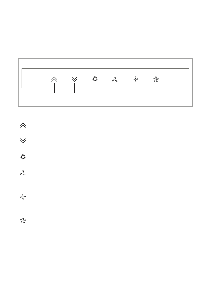
On O Light Low Middle High
Fig.1
Control panel
Touch the on key for 2 seconds to raise the extraction panel. Once the
extraction panel has risen halfway, the fan will start working at low speed
Touch the o key for 2 seconds to lower the extraction panel. Once the
extraction panel has descened halfway, the fan will stop operating
Press the light key to switch the lights on or o. Once the extraction
panel descends to halfway, the lights will switch o automatically
Touch the low key to start the fan at the lowest setting. Touch again to
turn o the fan. Touching either the middle or high keys will change the
fan setting
Touch the middle key to start the fan at the middle setting. Touch again
to turn o the fan. Touching either the low or high keys will change the
fan setting
Touch the high key to start the fan at the highest setting. Touch again to
turn o the fan. Touching either the low or middle keys will change the
fan setting
Timer Function
Touch any of the fan setting keys for 3 seconds when the
appliance is on and the key will flash. The extractor will enter
timer mode and will automatically stop after 15 minutes.

6| Instruction Manual
Care and Maintenance
IMPORTANT: DO NOT PERFORM MAINTENANCE OR
CLEANING OF THE EXTRACTOR WITHOUT FIRST SWITCHING
OFF THE ELECTRICITY SUPPLY.
Cleaning
You should use a non-abrasive cleaner. Any abrasive cleaner
(including Cif) will scratch the surface and could erase the control
panel markings.
You can clean your extractor eectively by simply using a dilute
solution of water and mild detergent and drying to a shine with a
clean cloth.
Cleaning the grease filter
The grease filter should be kept clean to minimise the risk of fire.
At least once a month you should remove and clean the grease
filter with hot soapy water. You can also wash the grease filter in
a dishwasher, ensuring that you place it in an upright position to
prevent damage from other items in the dishwasher. After rinsing
and drying, replace the filter.
To remove and replace the grease filters
Touch the On key so the moving panel raises to its full extent,
then isolate the power supply so it stays raised
By pulling the two top corners of the front glass panel at the
same time, it will be released and pivot toward you
The grease filter can then be pulled forward and out
Replacement is a reversal of the removal procedure
Please note:
Cleaning the grease filters in the dishwasher may lead to
discolouration. This is normal and does not constitute a fault with
the appliance.
Instruction Manual | 7
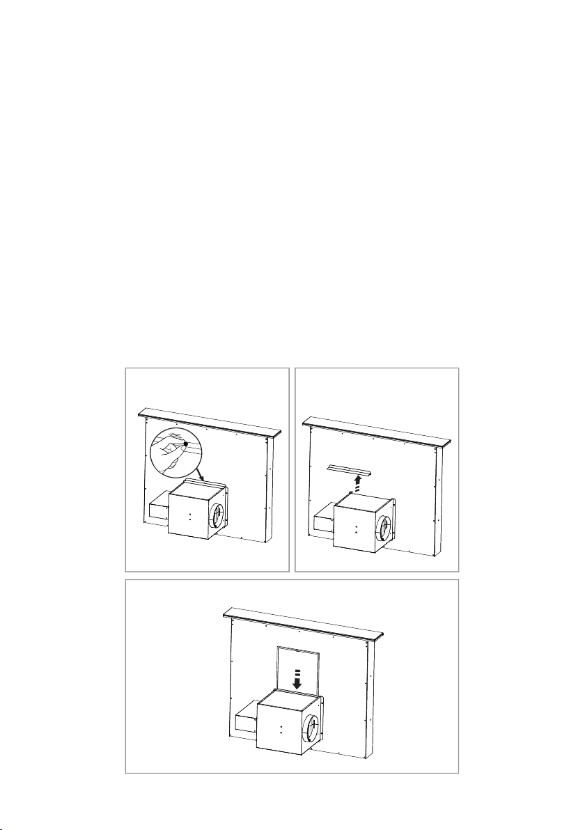
Changing the charcoal filter
To ensure the best performance of your extractor, you should
replace the charcoal filter every four to six months, depending
on use.
To replace the charcoal filter:
• Unscrew the panel on top of the motor housing box by
turning the black screw counter clockwise as shown in fig.2
and remove the panel as shown in fig.3
• Hold the tab of the filter towards you and lower the filter
down in to the opening as shown in fig.4
• Attach the magnetic strips to the extractor body leaving the
tab slightly tilted upwards to allow for easy removal
• Replace the panel on top of the opening and screw it back in
Fig.2 Fig.3
Fig.4

8| Instruction Manual
Mounting your extractor
When the extractor is to be installed behind a gas hob, the
minimum distance between the hob and extractor must be 30mm.
If fitting behind an electric hob, the minimum distance between the
hob and extractor must be 20mm.
If the instructions provided with your gas hob state that the
required distance between the hob and extractor must be greater
than specified above, then that is the distance that should be
observed; this is a legal requirement and may lead to your hob
being disconnected from the gas supply and the installation being
reported to RIDDOR.
IN THE ABSENCE OF ANY INSTRUCTIONS SUPPLIED WITH
THE GAS HOB, THE MINIMUM DISTANCE BETWEEN THE HOB
AND EXTRACTOR MUST BE AT LEAST 30mm.
The width of any hob must not be greater than the width of the
extractor installed with it.
Ducting and ventilation
For best performance and lowest noise output, we recommend
the use of 150mm ducting. Use of any smaller ducting will reduce
performance and increase noise
The length of ducting should not exceed 5 metres in total
Limit the use of elbows in the ducting to a minimum. Bear in mind
that each elbow imposes a similar restriction to flow to a 1 metre
length of straight ducting
Avoid abrupt changes in direction for the ducting
Ensure that the ducting used satisfies all local and national
standards applicable to the installation
Instruction Manual | 9
Troubleshooting
In the event of your appliance requiring technical assistance and/or
spare parts, please contact CDA Customer Care.
In this case it is necessary to state all the appliance data on the
rating plate, such as model, serial number etc. This information can
be found behind the grease filter.
CDA Customer Care
Phone: 01949 862 012
Email: customer[email protected]
Problem Reason Solution
The appliance does not
work
No power/ power outage Check the fuse, replace if
blown
Wires have disconnected Ensure the power supply is
securely connected
Output of appliance is
low
Setting is too low for
amount of fumes present Try a higher speed setting
Inadequate ventilation in
the kitchen
Ensure the kitchen has
sucient air intake
Charcoal filter (if fitted) is
blocked Replace the charcoal filter
Ducting is obstructed Remove any obstructions
from the ducting
Exit flaps on the motor
housing are restricted
Ensure any obstructions
are removed so the flaps
can move freely
Extractor stops mid
operation
There is a power outage Check the power supply
The circuit breaker or fuse
has tripped
Check the circuit breaker
or fuse
10 | Instruction Manual
Installation
1) Prior to installation, check that all
parts are present and free from transit
damage. In the event of damage
being discovered contact your
supplier and do not proceed with
installation
2) Before making a cut-out in the
kitchen cabinets or worktop,
ensure that there are no structural
(or other) obstructions that would
hinder installation. Ensure that the
cabinet dimensions are sucient to
accommodate the extractor, allowing
for the specified clearance between
the final installed positions of the
extractor and the hob
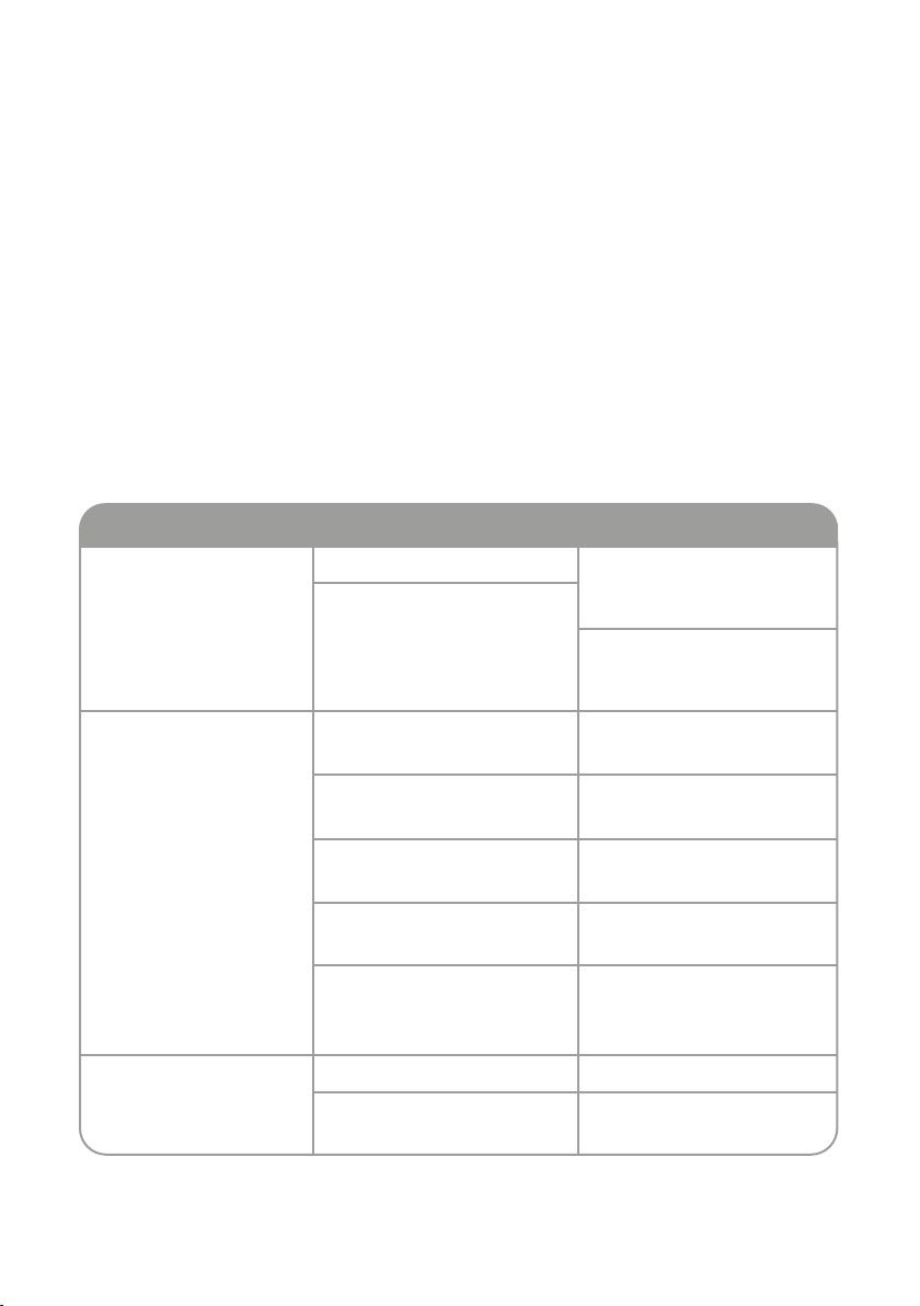
3) Make a rectangular cut-out in the
worktop to accommodate the
extractor.
The dimensions of the cut-out should
be:-
EDD62 - 510 x 100mm
EDD92 - 810 x 100mm
90
580/880
328
114
MAX1045
MAX330
255
260
MIN720
261
150
360
Fig.5
We recommend that you seek the help
of another individual when installing
this product. The fixings supplied are
suitable for most installations. It is the
responsibility of the installer to ensure
that the fixings are suitable for the
cabinets in the property.
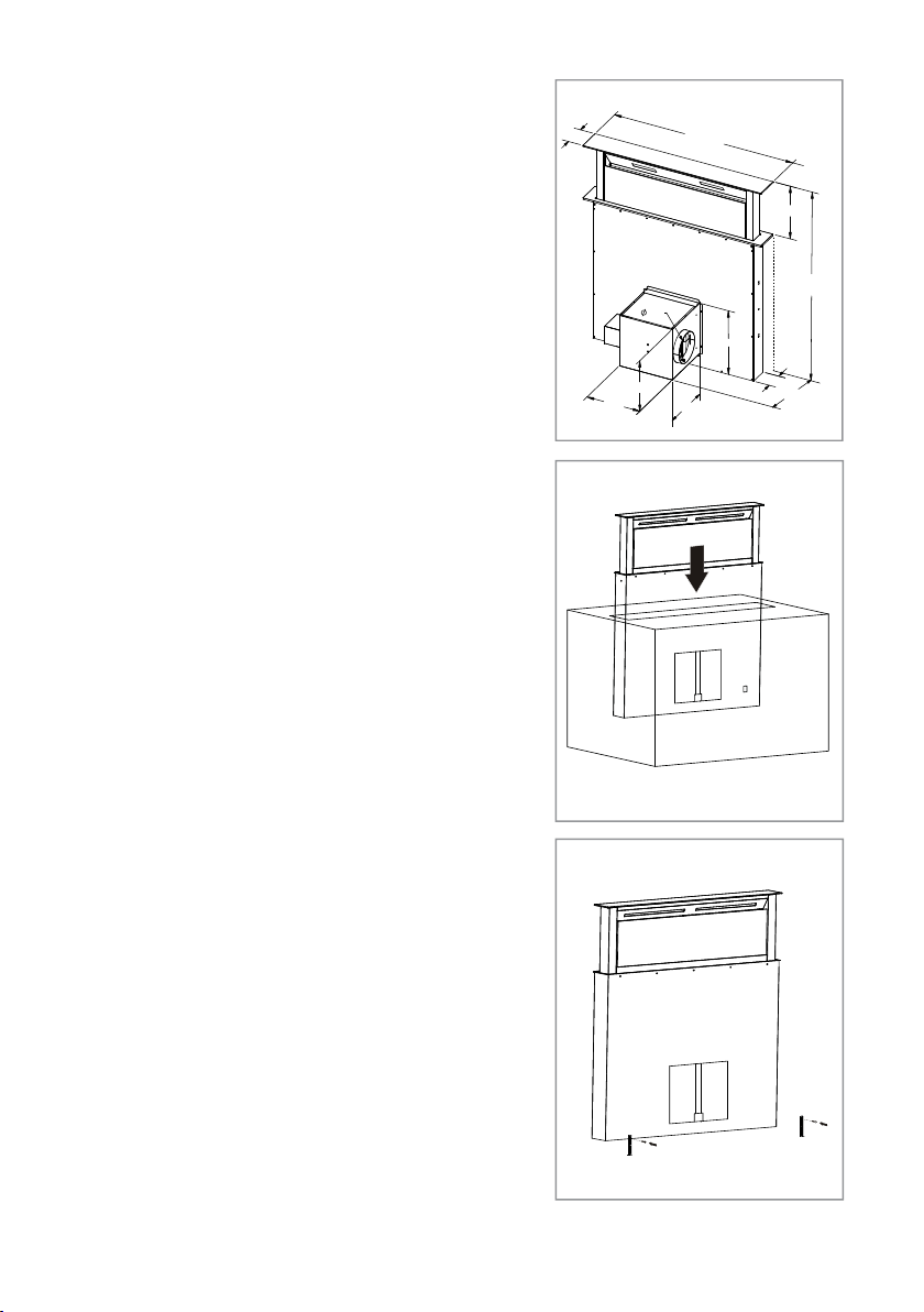
Fig.7
Fig.6
This manual suits for next models
1
Table of contents
Other CDA Ventilation Hood manuals


