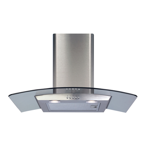
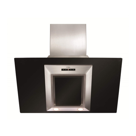
CDA EVQ71 Quick start guide

www.cda.eu
EVQ71
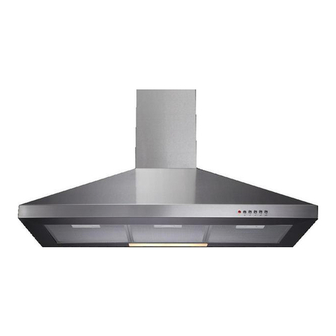
Extractor
Installation, use and maintenance
Cod:0103085718

2
Contents:
3Important
4 Dimension drawing
5Important information
6 Using your extractor
7Care and maintenance
9 Troubleshooting
10 - 13 Installation
10 Installation - height
11 Installation - preparation and ducting
12 Installation - mounting theextractor
14 Mains electrical connection
17 Energy eciency information

3
Important
TheCDA Group Ltdcannot beheld responsible for injuries or losses
caused by incorrect use or installation of this product.Please note
that CDA reservetheright toinvalidatetheguarantee supplied with
this product following incorrect installation or misuse of theappliance
or use in acommercial environment.
This appliance is not designed tobeused by people (including
children) with reduced physical, sensorial or mental capacity,or
wholack experience or knowledgeabout it,unless they havehad
supervision or instructions on how touse theappliance by someone
whois responsible for their safety.
Under no circumstances should any external covers beremoved for
servicing or maintenance except by suitably qualified personnel.
Appliance information:
Please enter thedetails on theappliance rating platebelow for
reference, toassist CDA Customer Care in theevent of afault with
your appliance and toregister your appliance for guarantee purposes.
Appliance Model
Serial Number
EU Declarations of Conformity:
This appliance has been manufactured tothestrictest standards and
complies with all applicable legislation, including Gas safety,Electrical

4
safety (LVD) and Electromagnetic interference compatibility (EMC).
IMPORTANT INFORMATION FOR CORRECT DISPOSAL OF THE
PRODUCT IN ACCORDANCE WITH EU DIRECTIVE 2012/19/EU.
At theend of itsworking life, theproduct must betaken toaspecial
local authority wastecollection centre or toadealer providing
appliance recycling services.
Disposing of ahousehold appliance separately avoids possible
negativeconsequences for theenvironment and health.It also
enables theconstituent materials toberecovered, saving both energy
and resources. Asareminder of theneed todispose of household
appliances separately,theproduct is marked with acrossed-out
wheeled dustbin.
Fig.1Dimensions

5
Please note:
•Under no circumstances should theextractor be
connected toany gas ventilation system, flue system or
hot air ducting system.
•Donot vent theextractor intoan attic or loft space.
•Only house theextractor in rooms with adequate
ventilation. Remember that theextractor is powerful and
whatever air is extracted needs tobereplaced.
•Donot tile theextractor in. It should beremovable for
service or maintenance.
•Donot use silicone sealant tosecure thehood tothewall.
•You must beable toisolatetheextractor from themains
electrical supply after installation.
•This appliance has been designed tobeused in aroom
with avolume of less than 36m³.
•Steam cleaners must not beused when cleaning this
appliance.
•Theperformance of your extractor will vary depending
on anumber of factors. These include: typeof extraction,
length of ducting,room volume, ventilation available and
cleanliness of thefilters.

6
Using your extractor
For best performance, you should switch on theextractor 15 minutes
before starting tocook and leaveit torun for approximately 15 minutes
after theend of cooking (you can use thetimer function for thelatter).
Control Panel
A- Speed 3key
B- Speed 2 key
C- Speed 1key
D- Lamp key
E- Power key
To switch the extractor on or change the speed
Touch any of thespeed keys(A,B or C).
To switch the extractor lights on and o
Touch thelamp key (D)
To switch the extractor o
Touch thepower key (E) twice.
To activate the timer function
Touch thepower key (E) once whilst theextractor is running on any
speed. This will set theextractor torun for approximately 15 minutes
before stopping automatically.
Fig.2
A
B
C
D
E

7
Care and maintenance
IMPORTANT: DO NOT PERFORM MAINTENANCE OR CLEANING
OF THE EXTRACTOR WITHOUT FIRST SWITCHING OFF THE
ELECTRICITY SUPPLY.
Cleaning
You should use anonabrasivecleaner. Any abrasivecleaner
(including Cif) will scratch thesurface and could erase thecontrol
panel markings.
You can clean your extractor eectively by simply using adilute
solution of water and mild detergent and drying toashine with aclean
cloth,for example amicro-fibre cloth.
Cleaning the grease filter
Thegrease filter should bekept clean tominimise therisk of fire.
At least once amonth you should removeand clean thegrease
filter with hot soapy water. You can also wash thegrease filter in a
dishwasher, ensuring that you place it in an upright position toprevent
damagefrom other items in thedishwasher.
Toremovethegrease filter,
push in thebutton on the
handle and then pull down on
thefilter at thefront as shown in
Fig.3. When you havereleased
it at thefront,then you can pull
thefilter out completely.
Fig.3

8
After rinsing and drying,reassemble thegrease filter tothehood by
reversing theremoval process.
Please note:
Cleaning thegrease filter in thedishwasher may lead to
discolouration. This is normal and does not constituteafault with the
appliance.
Changing the charcoal filter (re-circulating mode only)
Toensure best performance of your extractor, you should replace
thecharcoal filters every four tosix months, depending on use. The
charcoal filters are an optional accessory.These are available from
theCDA Sales team on 01949 862010 under code CHA33.
To attach the charcoal filters:
•Removethegrease filter as described on theprevious page.
•Aligntheslotson thecharcoal filter with thenotch on theside of the
motor. Place thefilter ontothemotor and turn clockwise slightly.The
filter should hold firmly in place. Repeat with theother side.
•Finally,replace thegrease filter.
Fig.4
Motor
Charcoal
Filter

9
LED lighting
Troubleshooting
Please note:
Your extractor is equipped witha motor protection device that will
happen duringcookingwhen most or all ofthe zones/burners are
beingused simultaneously, or ifyour extractor is installed incorrectly,
lower than the recommended height.
This is normal, and the extractor will workagain once the motor has
If your extractor is not working:
2. Checkthat the fuse in the spur has not blown.
3. Checkthat the control panel is clean and free from grease
Contact CDA Customer Care
A: Customer Care Department, The CDA GroupLtd, Harby Road,
Langar, Nottinghamshire, NG13 9HY
T: 01949 862 012F: 01949 862 003 E: customer[email protected]
W: www.cda.eu
These are not user-replaceable.In the event ofa problem withthe
lightingplease contact CDA Customer Care for assistance.Contact
details are on the rear cover ofthis manual.

10
Installation - height
When theextractor is tobeinstalled
aboveaCDA electric hob,theminimum
distance between thehob and extractor
must exceed 600mm.
When theextractor is tobeinstalled
aboveaCDA gas hob,theminimum
distance between thehob and extractor
must exceed 700mm.
If theinstructions provided with your
gas hob statethat therequired distance
between thehob and extractor must
begreater than 700mm, then that is
thedistance that should beobserved; this is alegal requirement and
may lead toyour hob being disconnected from thegas supply and the
installation being reported under RIDDOR.
Note: Theheight should bemeasured from thetop of theburners to
thegrease filter.
•IN THE ABSENCE OF ANY INSTRUCTIONS SUPPLIED WITH
THE GAS HOB, THE MINIMUM DISTANCE BETWEEN THE HOB
AND EXTRACTOR MUST BE AT LEAST 760mm.
•The width of any hob must not be greater than the width of the
extractor installed above it.
•Always bear servicing in mind. The extractor should always be
easily accessible or removeable after installation.
Gas: 700mm minimum
Electric: 600mm minimum
240.6
75
50
120
Fig.5
11
Installation - preparation and ducting
The metal casing of this appliance has been coated with a
preservative to protect it during transport and storage. This should
be removed during installation by using a non-abrasive stainless
steel cleaner. Always follow the instructions given with the cleaner
being used. Please ensure that there is no power being supplied to
the appliance whilst you do this.
Ducting
For best performance and lowest noise output,we recommend the
use of 150mm ducting.Lesser diameter ducting may beused but
this will reduce performance and increase thenoise of theextractor.
Wherever possible use rigid circular pipewhich has asmooth interior,
rather than theexpanding concertina typeducting.Thelengthsof the
ducting without performance being aected are as follows:
•4 metres with 1x90° bend.
•3metres with 2 x90° bends.
•2 metres with 3x90° bends.
Note:
•Werecommend that you seek thehelp of another individual when
installing this product.
•Werecommend that you wear PPEwhen handling this extractor.
•Thefixingssupplied are suitable for most installations. It is the
responsibility of theinstaller toensure that thefixingsare suitable
for theceiling typein theproperty.
•Cover any hob, or surface below the area in which the extractor
is to be installed, so that no damage befalls it.

12
Installation - mounting the extractor
Thefirst thing todo is toremovethegrease filter as per page7.
Theextractor body is held in place by four screws. Thepositions of
these screws, relativetothecentre line of thebody,are shown in Fig.
5on page10. Overall dimensions of theextractor are shown in Fig.1
on page4.
With thefinal position in mind, mark out thehole positions on thewall
upon which theextractor will bemounted. If theheight of thekitchen/
installation allows for both chimney sections tobeused, then a
bracket is provided tosecure theupper section in place. This, shown
in Fig.6,should beprepared and fitted now.
Please note: If you are
recirculating theair through
charcoal filters (and not ducting
totheoutside) and only have
room for one chimney section,
then thepiece with slitsat the
top should beused. This allows
air toescapeback intothe
kitchen.
Drill out theholes and insert wall
plugsor fittingsrequired for the
surface. Make sure no electrical
cables or similar lie behind the
surface being drilled.
Fig.6

13
Insert two screws intotheupper two holes of thefour that havebeen
prepared for theextractor body.Carefully,with thehelp of another, lift
theextractor intoplace and guide it ontothese screws. Tighten these
screws, from inside theappliance, if possible.
Insert two screws intothetwo lower wall holes through thepre-drilled
holes in theextractor body (from theinside).Theextractor should now
besecurely mounted on thewall.
Secure any ducting totheextractor and mount thechimney pieces.
Secure thelower section as per Fig.7and then raise and secure the
upper section as per Fig.8.
Fig.7Fig.8

14
Mains electrical connection
THIS APPLIANCE MUST BE CONNECTED TO THE MAINS SUPPLY
BY A COMPETENT PERSON, USING FIXED WIRING VIA A DOUBLE
POLE SWITCHED FUSE SPUR OUTLET AND PROTECTED BY A 3A
FUSE.
Werecommend that theappliance is connected by aqualified
electrician, whois amember of theN.I.C.E.I.C. and whowill comply
with theI.E.T.and local regulations.
Thewires in themains lead of this appliance are coloured in
accordance with thefollowing code:
Green & Yellow = Earth
Blue = Neutral
Brown = Live
Asthecolours of thewires in the
mains lead for theappliance may not
correspond with thecoloured markings
identifying theterminals connecting to
thefuse spur, proceed as follows:
•Thewire which is coloured green and yellow must beconnected to
theterminal marked E(Earth) or coloured green.
•Thewire which is coloured blue must beconnected totheterminal
marked N (Neutral) or coloured black.
•Thewire which is coloured brown must beconnected tothetermi-
nal marked L (Live) or coloured red.
DOUBLEPOLE
SWITCHED
FUSED SPUR OUTLET
USEA 3AMP FUSE

15
Note: Use a 3A Fuse.
Assembly and electrical connection should becarried out by
specialised personnel.
Theisolation switch and fuse for this appliance should beeasily
accessible after installation is complete.
Electrical information
Mains electrical voltage: 230-240Vac
Total rated power consumption:
74W

16
NOTES:

17
E & O E. All instructions, dimensions and illustrations are provided for guidance only. CDA reserve the
right to change specifications without prior notice.
Attribute Symbol Units
EVQ71noitacifitnedIledoM
Annual Energy Consumption AECHood
11.9 kWh
Time increase factor f
y FDEHood 30.3 (A)
x EEIHood 36.5 (A++)
Point
QBEP 212.2 m3/h
Point
PBEP 141 Pa
Maximum airflow QMAX 579.2 m3/h
Measured electric power at Best WBEP 27.4
4.0
330
W
Nominal lighting power WL W
Average illumination of the lighting
system on the cooking surface
EMiddle Lux
Measured power consumption in
standby
PS0.388 W
mode
PO0.335 W
Sound power level LWA 62 dBA
y GFEHood 69.8 (D) %
ELycneiciffepmaL Hood 82.5 (A)
Energy Efficiency Information
Value
%
0.9

Table of contents
Other CDA Ventilation Hood manuals
Popular Ventilation Hood manuals by other brands

Zanussi
Zanussi ZHC 920 operating instructions

Pando
Pando I-861 installation manual

Prizer Hoods
Prizer Hoods METAL LINERS installation instructions

Electrolux
Electrolux EFC6422 user manual

GE
GE PVW7361 installation instructions

KitchenAid
KitchenAid ISLAND CANOPY Installation Instructions and Use & Care Guide