CDA EZTK90BL Quick start guide

Customer Care Department • The Group Ltd. • Harby Road • Langar • Nottinghamshire • NG13 9HY
T : 01949 862 012 F : 01949 862 003 E : customer.care@cda.eu W : www.cda.eu www.cda.eu
EZTK90BL
Extractor
Installation, Use and Maintenance

2
Contents:
3 Important
4 Important information
6 Using your extractor
7 Care and maintenance
8 Removing the grease filter(s)
9 Changing/fitting the charcoal filter(s)
10 Changing the light
10 - 16 Installation
11 Installation preparation - height
13 Ducting and ventilation
17 Mains electricity connection
18 Electrical information
18 Troubleshooting
19 Energy Eciency Information

3
Important
The CDA Group Ltd cannot be held responsible for injuries or losses
caused by incorrect use or installation of this product. Please note that
CDA reserve the right to invalidate the guarantee supplied with this
product following incorrect installation or misuse of the appliance or
use in a commercial environment.
This appliance is not designed to be used by people (including
children) with reduced physical, sensorial or mental capacity, or
who lack experience or knowledge about it, unless they have had
supervision or instructions on how to use the appliance by someone
who is responsible for their safety.
Under no circumstances should any external covers be removed for
servicing or maintenance except by suitably qualified personnel.
Appliance information:
Please enter the details on the appliance rating plate below for
reference, to assist CDA Customer Care in the event of a fault with
your appliance and to register your appliance for guarantee purposes.
Appliance Model
Serial Number
EU Declarations of Conformity:
This appliance has been designed, constructed and marketed in
compliance with safety requirements of EU Directive 2014/35/EU (LVD)

4
and requirements of EU Directive 2014/30/EU (EMC).
IMPORTANT INFORMATION FOR CORRECT DISPOSAL OF THE
PRODUCT IN ACCORDANCE WITH EC DIRECTIVE 2012/19/EU.
At the end of its working life, the product must be taken to a special
local authority waste collection centre or to a dealer providing
appliance recycling services.
Disposing of a household appliance separately avoids possible
negative consequences for the environment and health. It also
enables the constituent materials to be recovered, saving both energy
and resources. As a reminder of the need to dispose of household
appliances separately, the product is marked with a crossed-out
wheeled dustbin.
Please note:
•Under no circumstances should the extractor be connected to any
gas ventilation system, flue system or hot air ducting system.
• Do not vent the extractor into an attic or loft space.
•Only house the extractor in rooms with adequate ventilation.
Remember that the extractor is powerful and whatever air is
extracted needs to be replaced.
•Do not tile the extractor in. It should be removable for service or
maintenance.
•Do not use silicone sealant to secure the hood to the wall.
•You must be able to isolate the extractor from the mains electrical
supply after installation.

5
•This extractor has been designed to be used in a room with a
volume of less than 36m.
•Steam cleaners must not be used when cleaning this appliance.
•The performance of your extractor will vary depending on a number
of factors. These include: type of extraction, length of ducting, room
volume, ventilation available and cleanliness of the filters.
Important information relevant to the reduction of the overall
impact of the cooking process on the environment:
•When cooking with pots and pans, always cover them with lids
where possible.
•Remember to switch the extractor o at the end of cooking (or use
the countdown timer available on some models)
•Remember to turn o the extractor lighting at the end of cooking
and avoid using the lights for ambient lighting.
•Use appropriate cookware for the cooking zone to be used on your
hob and, with gas hobs, adjust the flame to the size of the pot.
•Utilise the highest speed on your extractor when cooking fume
levels are high.
•Clean the grease filter(s) regularly and replace any charcoal filters
regularly if extracting via recirculation.
6
Using your extractor
For best performance, you should switch on the extractor 15 minutes
before starting to cook and leave it to run for approximately 15
minutes after the end of cooking.
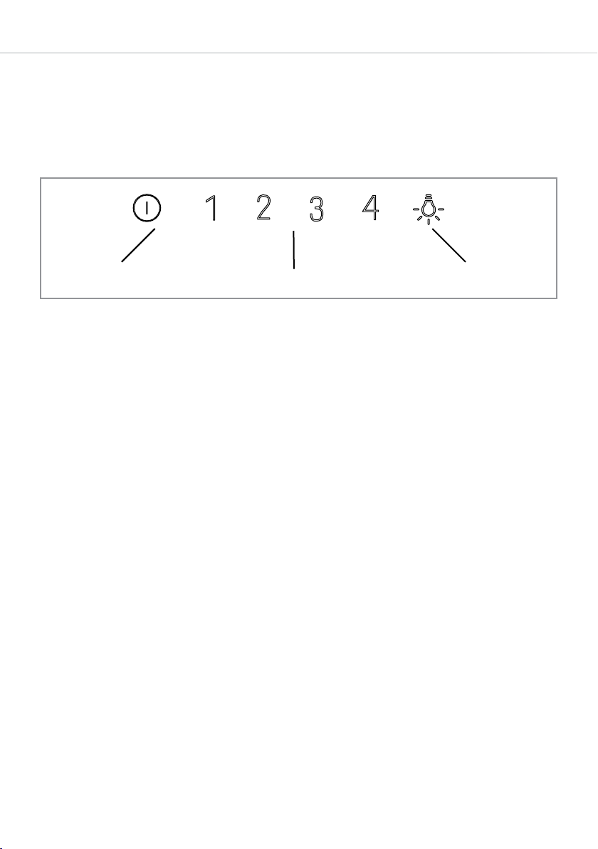
Control Panel
A - Power o button
B - Speed level buttons
C - Light button
To switch the extractor light on or o
• Press the light button (C).
To switch on the extractor or to change the speed at any time
when the extractor is running
• Press the relevant speed button (B) for the first, second, third or
fourth speed level as required.
• Press and hold the relevant speed button (B) to activate the timer
countdown for that speed. This timer lasts for approximately 10
minutes before switching the speed o. It can be deactivated at any
point by pressing the same speed sensor.
To switch the extractor o
• Press the power o button (A).
7
AB
Fig. 1 C

7
Care and maintenance
IMPORTANT: DO NOT PERFORM MAINTENANCE OR CLEANING
OF THE EXTRACTOR WITHOUT FIRST SWITCHING OFF THE
ELECTRICITY SUPPLY.
Cleaning
You should use a non-abrasive cleaner. Any abrasive cleaner
(including Cif) will scratch the surface and could damage the control
panel markings.
You can clean your extractor eectively by simply using a dilute
solution of water and mild detergent and drying to a shine with a
clean cloth.
Take care not to use water in excess when cleaning the extractor.
This will help to prevent water entering the internal workings of the
extractor and therefore help to preserve its life-span. We recommend
keeping the cleaning cloth only damp at all times.
When cleaning the stainless steel trims on the appliance, we
recommend cleaning in the same direction as the brush finish on the
steel (i.e. horizontally). This will help to prevent unsightly markings.
IMPORTANT:
Always protect surfaces immediately beneath the extractor (such
as a hob) with a clean, dry towel or similar item before carrying
out any cleaning or maintenance in case of falling parts/items.
8
3
Removing and cleaning the grease filter(s) - Fig. 2
The grease filters should be kept clean to minimise the risk of fire.
At least once a month you should remove and clean the grease
filters with hot soapy water. You can also wash the grease filters
in a dishwasher (see note on page 9), ensuring that you place it
in an upright position to prevent damage from other items in the
dishwasher. After rinsing and drying, refit the filters.
To remove the grease filter, lift open the extractor cover and then
release the catch on the handle on the grease filter. It will release at
the handle side. Then lower the grease filter to remove it completely
(fig. 2). To replace the grease filter, repeat the steps in reverse.
Fig. 2

9
Please note:
Cleaning the grease filters in the dishwasher may lead to
discolouration. This is normal and does not constitute a fault with the
appliance.
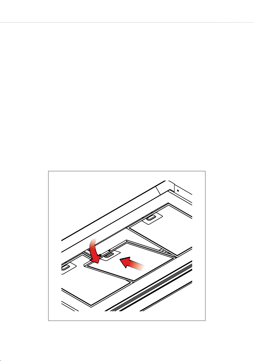
Changing the charcoal filter (re-circulating only) - Fig. 3
To ensure best performance of your extractor, you should replace the
charcoal filters every four to six months, depending on use.
To attach a new charcoal filter, first remove the grease filters as
described above. Then oer up the charcoal filter to the inside of the
grease filter as shown in fig. 3. Oer the catches on the bottom of the
charcoal filter to the grease filter frame (1) and then clip the top of the
charcoal filter into the grease filter frame around the handle area (2).
Then, replace the grease filters and cover panels.
Fig. 3
1
2
3

10
Changing the light
This appliance is fitted with energy saving LED lighting that has a
considerably longer life expectancy than traditional filament bulbs.
These are not user-replaceable in the unlikely event of a failure.
If the lights on your extractor should fail, please contact CDA
Customer Care. Contact details are below, on page 18 and on the
rear cover of this manual.
Do not touch bulbs or adjacent areas during or straight after
prolonged use of the lights.
The light is designed for use during cooking and not for general room
illumination. Extended use of the light can reduce the life span of the
light assembly.
Contact CDA Customer Care
A: Customer Care Department, The CDA Group Ltd, Harby Road,
Langar, Nottinghamshire, NG13 9HY
T: 01949 862 012 F: 01949 862 003
Installation
When installing this product we recommend you seek the help
of another individual. This product may have some sharp edges.
Please take care and wear adequate PPE when handling.
Table of contents
Other CDA Ventilation Hood manuals


