Installation and Operation Manual MiniMax
© CEDES/June 2009 www.cedes.com 7
6. Trouble shooting
If MiniMax does not operate as expected, observe
the following trouble shooting guide step by step:
1. Check supply voltage both on emitter and re-
ceiver. Are the green LED’s in the emitter and re-
ceiver cables on? Is the supply voltage between
10 and 30 Volts DC? The ripple on the DC volt-
age should not exceed more than 10 % of the
mean voltage.
2. If the output of the receiver (black wire) is high
when the protected area is not obstructed, and in
this case it should be low, connect the white wire
of the receiver cable to ground (blue wire, which
is also negative power, see page 8).
3. If the output of the receiver (black wire) is low
when the protected area is not obstructed, and in
this case it should be high, connect the white wire
of the receiver cable to the positive power (brown
wire, see page 8).
4. If the output signal of the receiver is not stable
during the closing of the door, make sure that
a. there is not excessive EMI-noise generated by
the door drive or the door inverter or any other
means that is disturbing the door edge. In
such a case, move the cable of the receiver so
that the distance to the noise source is as
wide as possible. In addition, filter the noise of
the source by using the optional Relay Module
or the optional Power Supply/Relay module
available from CEDES.
b. there are no obstacles between the emitter
and the receiver. Make sure that the door lock
or any other obstacle does not enter the light
path.
c. the edges are properly installed so that they
cannot swing or vibrate and therefore lose line
of sight between themselves.
d. the curved front surface of the edges are clean
and not full of dust or dirt. Although MiniMax is
very tolerant to this condition, its performance
is much better when it is clean.
5. If the doors are closing even with an obstacle1,
there are two possible reasons:
a. Output selector not properly set (see step 2
and 3)
b. Faulty/defective system wiring or defective re-
ceiver edge2
1Due to the nature of door system designs, (which as complete sys-
tems are not fail safe), in extremely rare conditions doors can close
even with an obstacle present. Therefore, there must be, by code,
other safety means to prevent passengers from being hurt by the
elevator doors. These dangerous situations should and can be de-
tected by the elevator control, which should, in such a case, take the
elevator out of service.
2This device (as well as all other door protection systems on the
market) cannot – by its nature – provide absolute safety for elevator
passengers passing through the doorway. It must not be used as the
final fail safe device of the door mechanism. This ultimate safety
function has to be provided by a fail safe force and kinetic energy
limiter.
Maintenance
Although MiniMax does not need periodical main-
tenance, a functional check at least with every
elevator maintenance check, or every 6 months is
strongly recommended. This periodic functional test
should consist of the following:
- Test the reopening function over the whole door
area. The door should reopen if an object is
placed anywhere between the sill and up to 1800
mm above the sill.
- Clean the front surface with a soft towel from dust
or dirt. Especially when the door edges are in-
stalled before the construction of the building is
finished (perhaps weekly during construction). To
clean the surface with a towel, it must be either
dry or slightly moist, but not wet.
- Confirm edges are fastened securely to the door
wings and slam post
- Confirm cables are routed properly as described
in the appropriate mounting kit installation instruc-
tions.
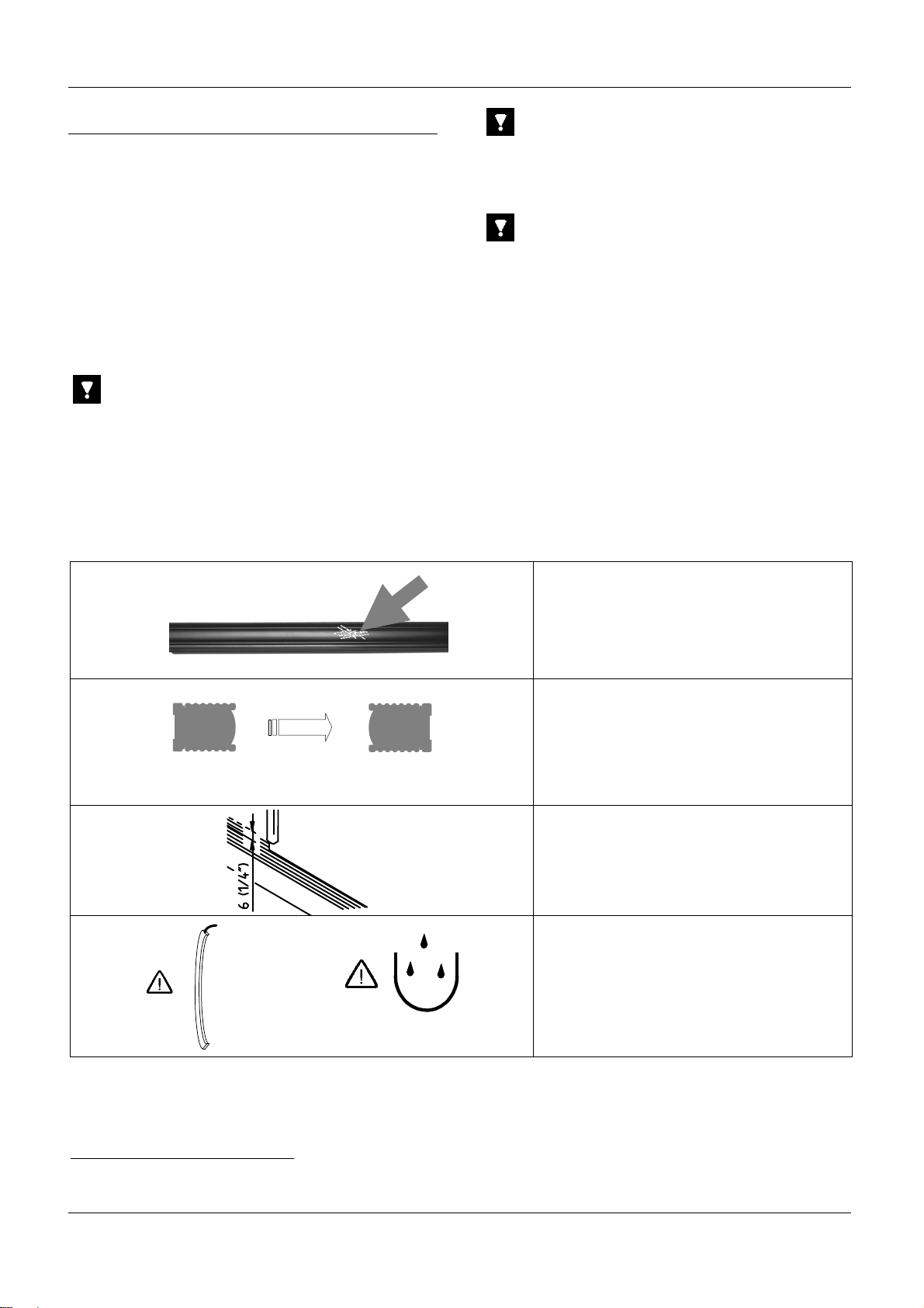
Important notices:
Never use any solvents, cleaners or mechanically
abrasive towels to clean the edge. The plastic lens
can be damaged!
Although the edges are water and weather resistant,
never use lots of water to clean the edges!
Never use high pressure water to clean the edges!
Do not scratch the surface when cleaning the edges!
Disregard of the mentioned precaution may lead to a
loss of safety!
Disposal
The light curtain should only be replaced if a similar
door protection device is installed. Disposal should
be done using the most up-to-date recycling technol-
ogy according to local rules and laws. There are no
harmful materials used in the design and manufac-
ture of the light curtain. Traces of such dangerous
materials could be used in the electronic compo-
nents but not in quantities that are harmful to health.