cegard/Max C/CM Bedienungsanleitung
10 www.cedes.com © CEDES/Mai 2012
Inhalt
1. Einführung........................................... 10
2. Merkmale............................................ 10
3. Anwendungen..................................... 10
4. Funktionsbeschreibung....................... 10
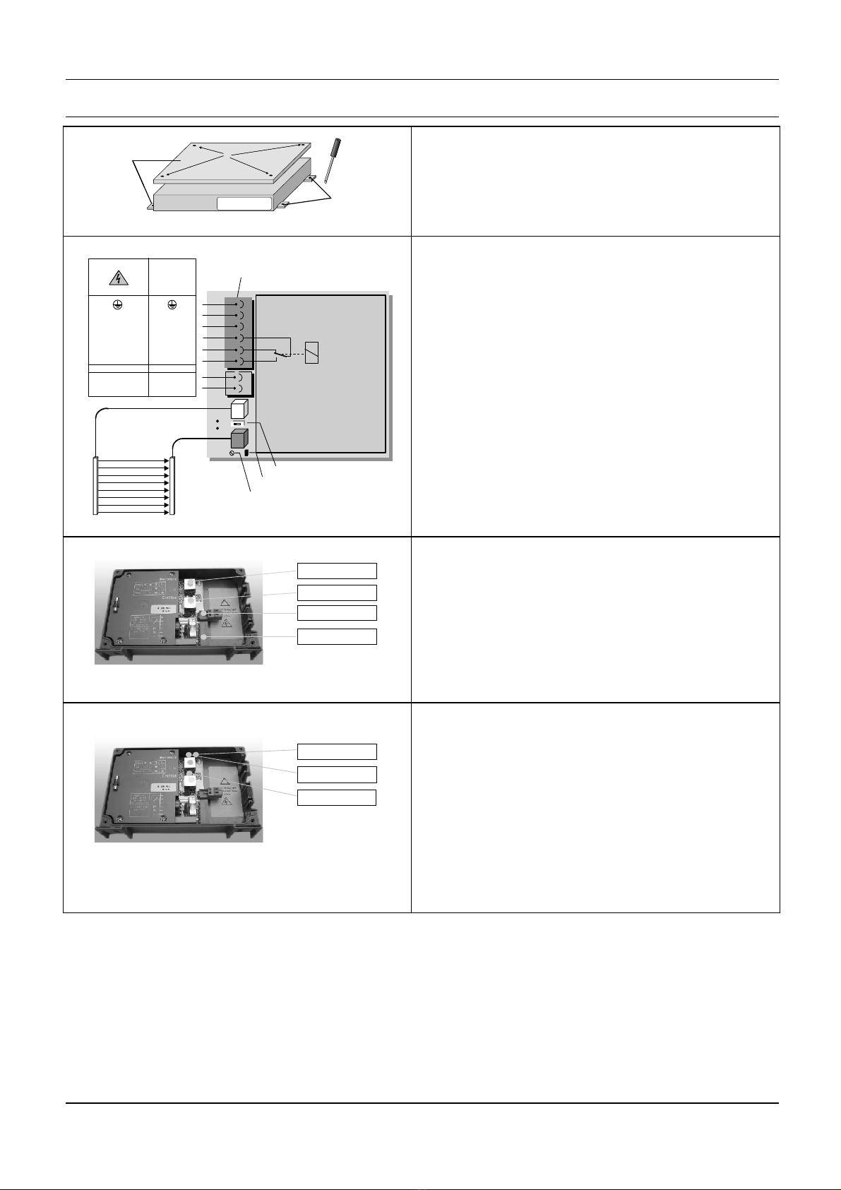
5. Montage .............................................. 11
5.1. Montage - Lichtvorhang ........................ 11
5.2. Montage - Steuergerät .......................... 12
5.3. Testeingang.......................................... 13
6. Wartung .............................................. 13
7. Fehlersuche und -behebung............... 14
8. Technische Daten ................................ 15
8.1. Lichtvorhang......................................... 15
8.2. Steuergerät........................................... 15
8.3. Dimensions / Abmessungen /
Dimensions .......................................... 23
9. Ordering information /
Bestellinformationen / Références ..... 25
9.1. Systems / Systeme / Systèmes ................ 25
9.2. Accessories / Zubehör / Accessoires....... 25
10. Certificate / Zertifikat / Certificat........ 26
10.1. CE Certificate / Konformitätserklärung /
Certificat de conformité......................... 26
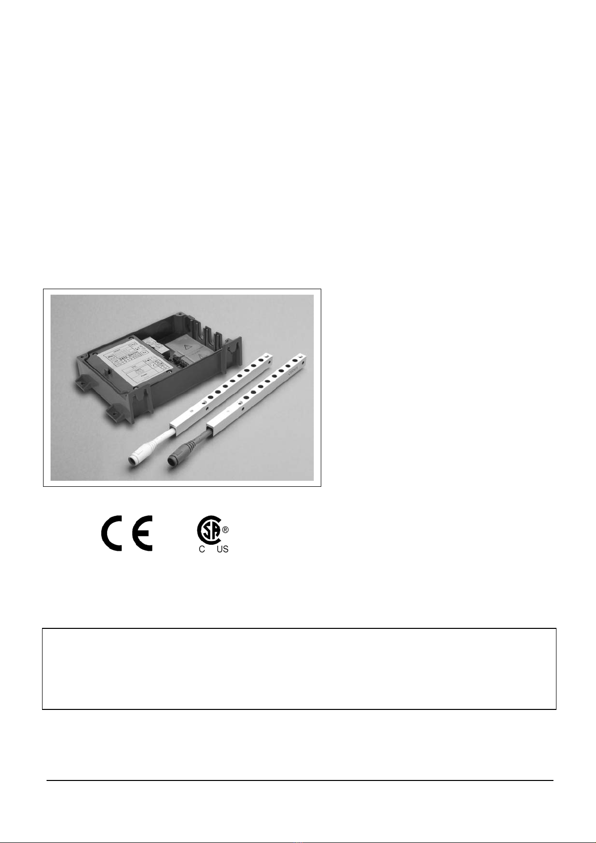
1. Einführung
Der Lichtvorhang cegard/Max C/CM erlaubt schnelle
und wirtschaftliche Modernisierungen. Dank seiner
hervorragenden Kompatibilität lässt sich der
cegard/Max C/CM problemlos in jeder Anlage
installieren. Die Position der einzelnen Strahlen
sowie die Betriebsreichweite lassen sich den
Anforderungen des Kunden entsprechend
millimetergenau einstellen.
Für sämtliche Türarten steht eine Vielfalt an
Montagekonfigurationen für einen problemlosen
Einbau und sofortigen Betrieb zur Auswahl. Der
Betrieb des cegard/Max C/CM erfolgt über eine
externe Steuereinheit, die mit Spannungen von 17
bis 240 V arbeitet.
2. Merkmale
Selbstkalibrierend, fehlertolerant
Einfache Inbetriebnahme ohne Justierung
Muting-Funktion
Dichtes Schutzfeld
Robust und betriebssicher
Integrierte Diagnose
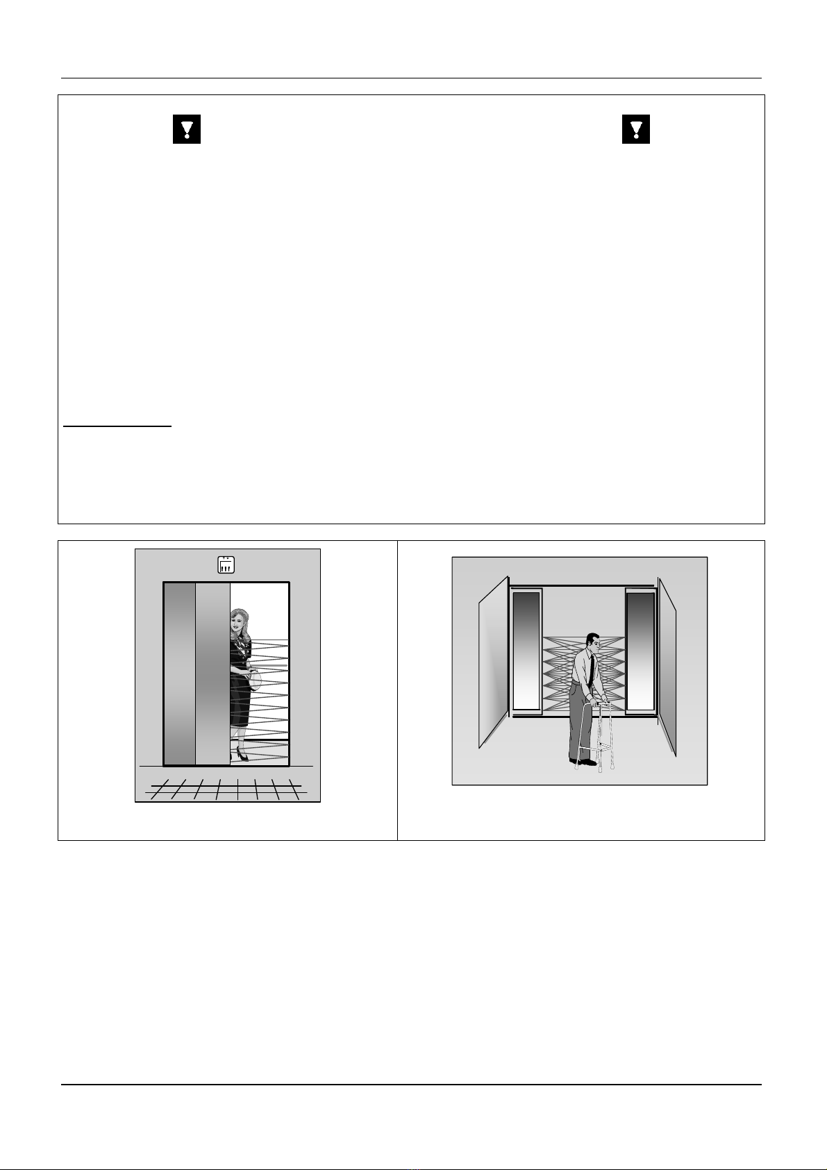
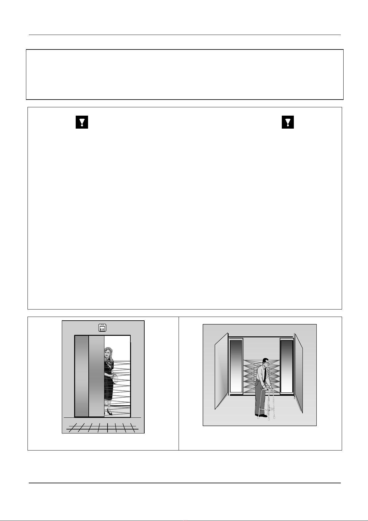
3. Anwendungen
cegard/Max C/CM eignet sich ideal zur
Verbesserung von Komfort und Sicherheit
automatischer Aufzugtüren sowie anderer
automatischer Türen. Es sind zahlreiche
Sonderkonfigurationen erhältlich.
cegard/Max C/CM darf weder als
Schutzvorrichtung für gefährliche Maschinen noch in
explosionsgefährdeten Atmosphären oder
radioaktiven Umgebungen eingesetzt werden.
4. Funktionsbeschreibung
Gerade und gekreuzte Strahlen bilden einen äußerst
dichten Schutzbereich zwischen Sender (Tx) und
Empfänger (Rx). Eine eingebaute Kalibrierfunktion
regelt die Stärke jedes einzelnen Strahls und macht
eine weitere Nachjustierung überflüssig. Diese
Funktion unterdrückt auch Störungen durch
Schmutz oder andere Lichtquellen und erkennt
automatisch die jeweilige Betriebsart. Aufgrund
dieser Merkmale bietet cegard/Max C/CM eine
herausragende Funktionssicherheit. Jegliche
Störungen des Schutzbereichs durch Personen oder
Objekte werden erfasst und lösen das
Ausgangsrelais aus.