Installation and Operation Manual cegard/Max-NT
© CEDES www.cedes.com 3
Table of Contents
1.
!
Operation ................................................... 3
!
2.
!
Failsafe Operation ..................................... 3
!
3.
!
Power Supply.............................................. 4
!
4.
!
Installation ................................................. 4
!
4.1.!Mounting transmitter and receiver ................ 5!
4.2.!Cable guidance .......................................... 6!
4.3.!Installation of the control unit....................... 6!
4.4.!Electrical Installation.................................... 7!
4.4.1.!Power supply ........................................ 8!
4.4.2.!Transmitter and Receiver Connections.... 8!
4.4.3.!Fire recall............................................. 8!
4.4.4.!Output relay......................................... 8!
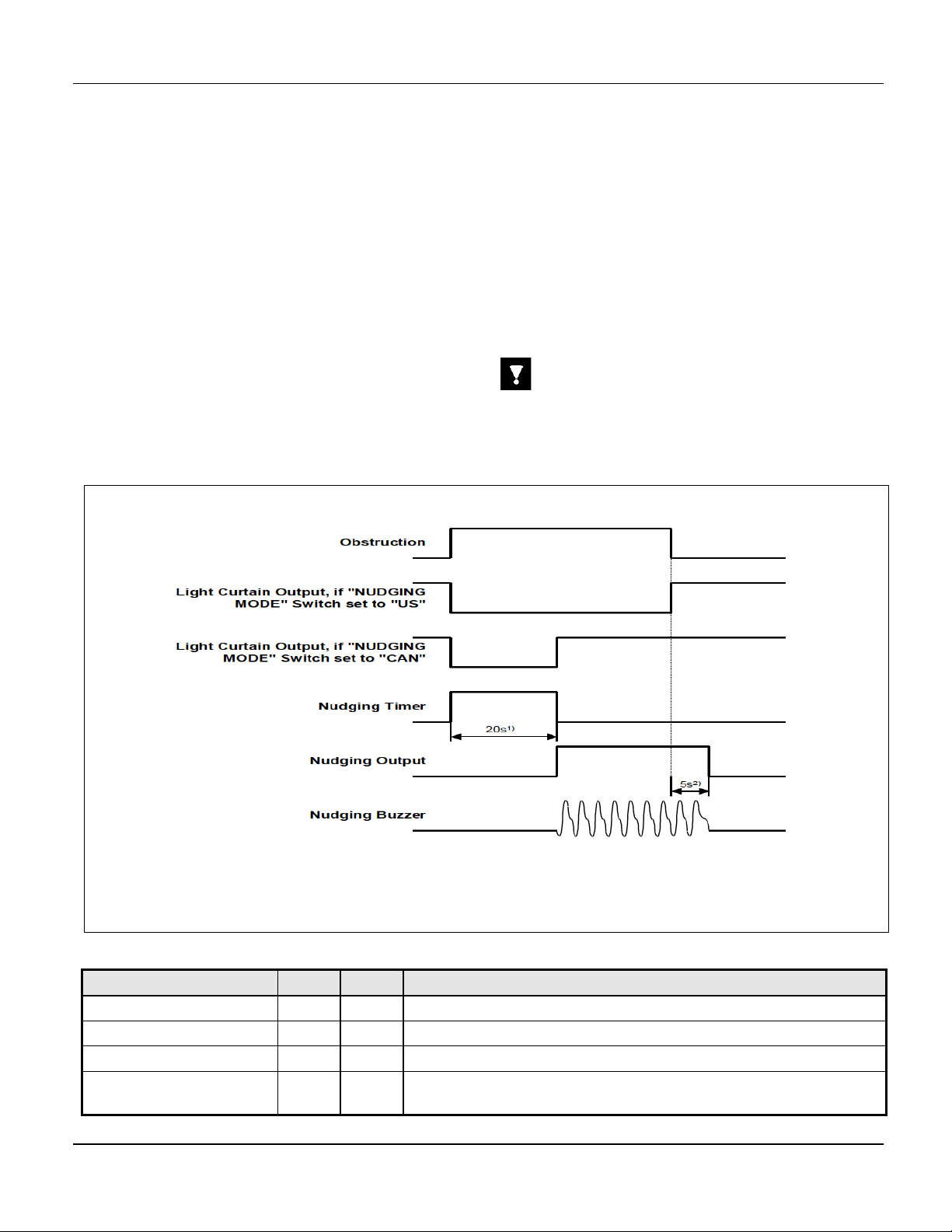
4.4.5.!Nudging and Nudging-AUX relay.......... 9!
4.4.6.!Nudging function.................................. 9!
4.5.!Power-up and test ..................................... 10!
4.6.!Snap on the vison shield............................ 10!
4.7.!Maintenance............................................. 11!
4.8.!Disposal ................................................... 11!
5.
!
Troubleshooting ....................................... 12
!
6.
!
Technical Data.......................................... 13
!
6.1.!Specifications ............................................ 13!
6.2.!Dimensions............................................... 14!
6.2.1.!Transmitter / Receiver ......................... 14!
6.2.2.!Control unit with housing .................... 15!
6.3.!Bill of material and part numbers............... 15!
1.
Operation
The cegard/Max-NT is ideal for improved comfort and
safety in elevator door protection applications where
nudging and fire recall functions are required in the light
curtain controller. Complete modernization kits, a vast
range of accessories and special configurations are
available.
The cegard/Max-NT infrared light curtain kits generally
include a control unit the following components:
(A) Transmitter edge with white connector
(B) Receiver Edge with blue connector
(C) Transmitter cable with white connectors
(D) Receiver cable with blue connectors
(E) Control unit.
Kits may also include the following components:
• Mounting profiles (MP),
• Spacer profiles (SP),
• Vision shields (VS)
• Ccable guide wires (CGW)
• Protective tubing (PT), and
• Additional hardware (e.g. screws, ties, etc.)
• Other accessory items
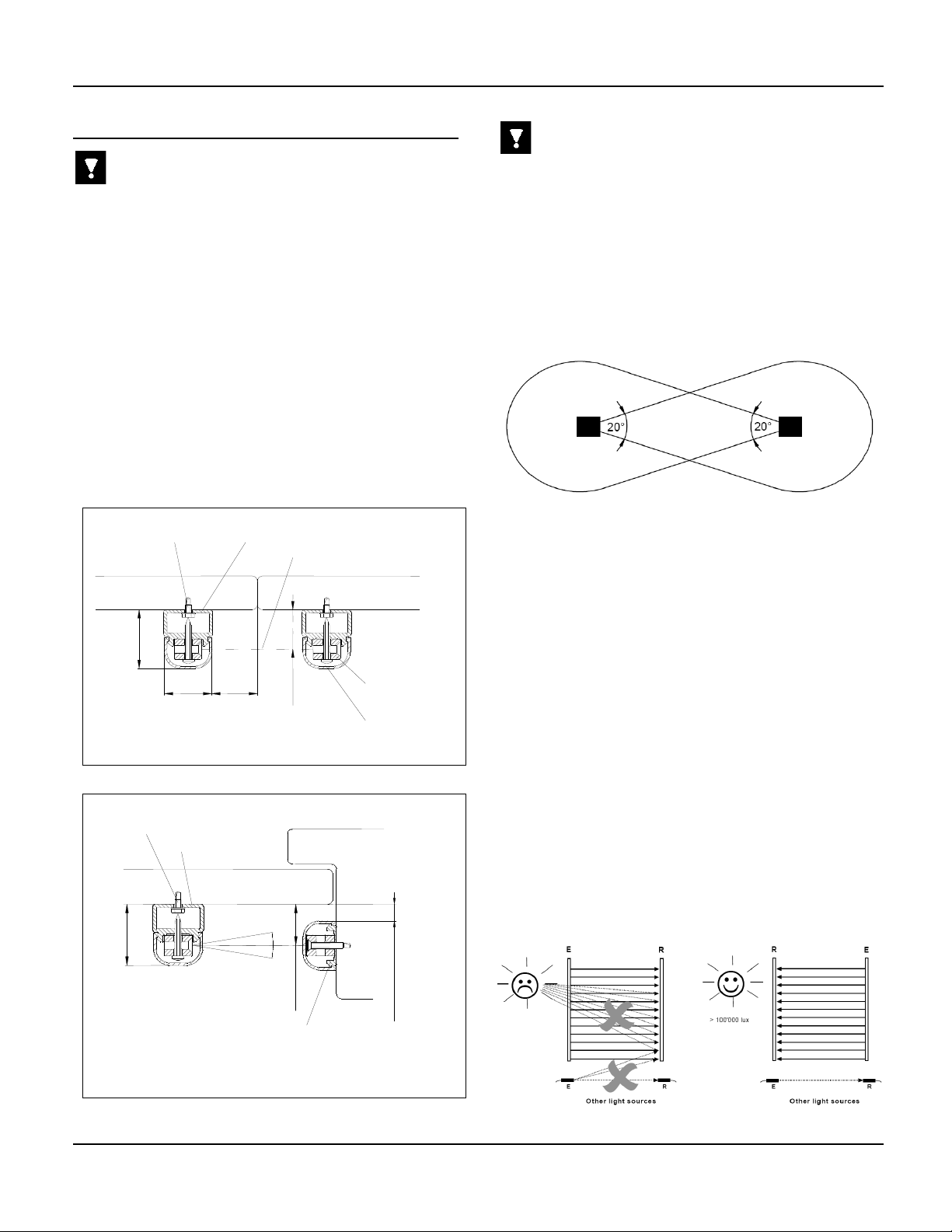
The transmitter and receiver should be mounted so that
the LEDs are facing opposite each other such that the
protective field that is formed between the transmitter
and receiver units provides the desired coverage (e.g.
the elevator cab entrance).
The cegard/Max-NT control unit is mounted within reach
of the ends of the transmitter and receiver cables (e.g.
on the car top or in a nearby operating panel). The con-
trol unit acts as an interface between the light curtain
system and the door control system.
To increase the lifetime of the electronic components,
especially the infrared transmitter elements, the control
unit continuously controls the light emitting power based
on the distance between the transmitter and the re-
ceiver. When the doors are closed, the emitting power
is nearly zero. This function also prevents optical by-
passing at the car door sill.
The mounting components included in the ce-
gard/Max-NT light curtain kit support both side opening
door and center opening elevator applications. The
components are suitable for new installations and the
modernization of existing elevators.
2.
Failsafe Operation
Important
During normal operation, the cegard/Max-NT light cur-
tain system provides comfort for passengers by signal-
ing the elevator control system to reopen the elevator
cab doors. That said, infrared door protection systems,
including the cegard/Max-NT light curtain system, can-
not provide absolute safety for elevator passengers
passing through the elevator cab entryway as they are
only a component of the overall elevator door protection
system.
Light curtains are not allowed to be the final failsafe de-
vice of the door mechanism. A failsafe force and kinetic
energy limiter must provide the ultimate safety function.
Due to the nature of door system designs, there are ex-
tremely rare occurrences when the elevator doors can
close even when an object or person is present. There-
fore, federal, state and local codes require other safety
means to prevent passengers from being hurt by the el-
evator doors during closure. These dangerous situa-
tions should be detected by the elevator control, which
should take the elevator out of service. Final safety re-
sponsibility remains with the elevator integrator and/or
contractor.