CEGA Remuv MV600-2 User manual

by
CEGA
Innovations
®
USER MANUAL
AIR SUPPLY
MV600-2
®


Table of Contents
Symbol Reference 2
Precautions & Intended Use 3-4
Electromagnetic Immunity 5
Parts Identication 6
Product Specications 7
Transportation & Storage 7
Operating the Air Supply MV600-2 8
Cleaning & Preventative Maintenance 8
Filter Care 9
Infection Control 9
Returns & Repairs 10
Internal Components 10
Warranty Terms and Conditions 11-12
Patents & Re-Order Information 13

Symbol Reference
REFER TO INSTRUCTION MANUAL/BOOKLET
THIS END UP
TYPE BF APPLIED PART
TEMPERATURE LIMITATION
ALTERNATING CURRENT
HUMIDITY LIMITATION
MANUFACTURER
DATE OF MANUFACTURE
KEEP DRY
CAUTION
ON (power) OFF (power)
CLASS II
NOT MADE WITH NATURAL RUBBER LATEX
2
120 V~, 60Hz, 10A
Complies with: ANSI/AAMI UL 60601-1 3rd Ed.,
CSA C22.2 No. 60601-1-1:14
CHECK YOUR LOCAL/STATE/FEDERAL/
INTERNATIONAL GUIDELINES BEFORE DISPOSAL.

Precautions and Intended Use
3
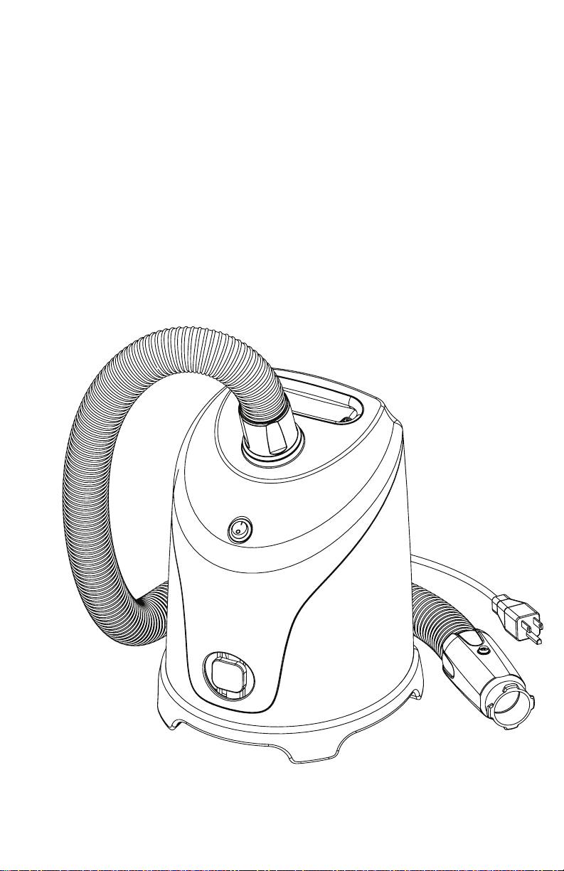
The Air Supply MV600-2 is intended for use with the REMUV™ Air Mat and
REMUV™ LP in hospitals and long-term or extended care facilities for the later-
al transfer of patients from one bed surface to another.
INTENDED USE
The caregiver/operator is the person handling the equipment.
The patient is not the intended operator.
1. Read and understand these instruction before using this device.
2. Never leave patient unattended on an inated device.
3. Use this product only for its intended purpose as described in this manual and the
REMUV™ or REMUV™ LP User Guide. Only use attachments and/or accessories that
are authorized by CEGA Innovations®.
4. Route the power cord to avoid hazard.
5. Avoid blocking air supply intakes.
6. When using the air supply in the MRI environment, a 25-ft. MRI hose is required
(available for purchase).
7. Avoid electric shock. Do not open the air supply. Do not attempt service or mainte-
nance while the air supply is in use.
8. NOTE: REFERENCE REMUV™ USER GUIDE FOR OPERATING INSTRUCTIONS PRIOR TO
USE.
9. Do not use the Air Supply MV600-2 in damp conditions.
10. Do not use the Air Supply MV600-2 if it is wet.
11. Wipe down the Air Supply MV600-2 with any facility approved cleaning agent only
after unplugging the product from the electrical outlet.
12. Never use the Air Supply MV600-2 if any part of the electrical cord or plug is dam-
aged. Never attempt repairs on your own. See pages 11-13 for warranty and order
information.
13. Operator must observe patient while the Air Supply MV600-2 is in use.
14. Position equipment for easy disconnection from power supply.
15. Not for use in an oxygen-enhanced environment.
16. Not for use in the presence of ammable anesthetics.
17. Avoid spillage, leakage, and ingress of liquids.
WARNING: To avoid the risk of electric shock, this equipment must only be
connected to a supply main with a protective earth ground connection.
WARNING: The Air Supply MV600-2 is not compatible with DC power
supplies.
WARNING: The Air Supply MV600-2 is intended only for use with the
REMUV™ product line.
WARNING: Risk of explosion in the presence of ammable anesthetics.
WARNING: No modication of this equipment is allowed.

WARNING: Use of this equipment adjacent to or stacked with other
equipment should be avoided due to risk of improper operation.
If such operation is unavoidable, this equipment and the other
equipment must be observed to verify that all equipment operates
normally.
WARNING: Use of accessories, transducers and cables other than
those specied or provided by the manufacturer of this equipment
may result in increased electromagnetic emissions or decreased
electromagnetic immunity of this equipment and result in improper
operation.
WARNING: Portable RF communications equipment (including
peripherals such as antenna cables and external antennas) should be
used no closer than 30 cm (12 inches) to any part of the Air Supply
MV600-2, including cables specied by the manufacturer. Failure to
comply with this warning may result in degradation of the perfor-
mance of this equipment.
NOTE: The EMISSIONS characteristics of this equipment make it
suitable for use in industrial areas and hospitals (CISPR 11 class A). If
the equipment is used in a residential environment (CISPR 11 class
B is normally required) this equipment might not oer adequate
protection to radio-frequency communication services. The user may
need to take mitigation measures, such as relocating or re-orienting
the equipment.
Electromagnetic Emissions
The Air Supply MV600-2 is intended for use in the electromagnetic environ-
ment indicated below.
RF Emissions CISPR 11: Group 1
FR Emissions CISPR 11: Class A
Harmonic Emissions: Class A
Voltage Fluctuations/Flicker Emissions: Compliant
NOTE: The Air Supply MV600-2 should be used in the following environmen-
tal conditions with: (a) an ambient temperature range of + 10 °C to + 40 °C,
(b) a relative humidity range of 30 % to 75 %, and (c) a standard atmospheric
pressure environment.
NOTE: Any equipment RF emissions will not likely cause interference with
nearby electronic equipment.
4

Electromagnetic Immunity
The Air Supply MV600-2 is intended for use in the electromag-
netic environment only as indicated below.
*UT is the AC Mains Voltage prior to application of the test.
NOTE: The Air Supply MV600-2 should be used in the following environmen-
tal conditions with: (a) an ambient temperature range of + 10 °C to + 40 °C,
(b) a relative humidity range of 30 % to 75 %, and (c) a standard atmospheric
pressure environment.
NOTE: This equipment is intended to functionally operate under conditions
where power quality is that of a normal hospital environment.
NOTE: The Air Supply MV600-2 has been designed and manufactured to emit
power frequency magnetic elds at levels characteristic of a typical setting in
a hospital environment.
5
I
MMUNITY
T
EST
IEC
60601
T
EST
L
EVEL
Electrostac Discharge (ESD)
± 6 kV contact
± 8 kV air
± 6 kV contact
± 8 kV air
Electrical Fast Transient/Burst
± 2kV for power supply lines
± 1kV for input/output lines
± 2kV for power supply lines
Not applicable
Surge
± 1kV line(s) to line(s)
± 2kV line(s) to earth
± 1kV differenal mode
Not applicable
Voltage Dips
Short Interrupons
Voltage Variaons on Power Supply Input
Lines
<5% UT (>95% dip in UT) for 0,5 cycle
40% UT (60% dip in UT) for 5 cycles
70% UT (30% dip in UT) for 25 cycles
<5% UT (>95% dip in UT) for 5 s
<5% UT (>95% dip in UT) for 0,5 cycle
40% UT (60% dip in UT) for 5 cycles
70% UT (30% dip in UT) for 25 cycles
<5% UT (>95% dip in UT) for 5 s
Power Frequency (50, 60 Hz) Magnec Field
3 A/m
3 A/m
C
OMPLIANCE
L
EVEL

Parts Identication
Air Supply
MV600-2
A. Power Switch
B. Hose Connection
C. Carry Handle
D. Air Intake
E. Power Cord
F. Adapter
6
A
B
D
C
E
F

Product Specications
Dimensions: 15 x 10 x 9” (38 x 25 x 23 cm)
Weight: 12 lbs (5.4 kg)
Housing Material: Fire Retardant PP and PC
Power Cord: 15 ft. (457 cm), 16 AWG, Hospital Grade
Service Life: 5 years
Power Input: 120V~, 60Hz, 10A
Power Output: 1100-1200 Watts
Air Flow Output: 3psi, 80 cfm
Warmed Air: Less than 105 F after 10 minutes use at room temperature
Noise level: Less than 80 dB (measured at 1 meter)
Filter: 2 Micron Sock type
Not made with natural rubber latex
Type of protection against electric shock: CLASS II EQUIPMENT
Degree of protection against electric shock: TYPE BF APPLIED PART
Protection against ingress of water: ORDINARY (not protected).
Duty Cycle: 30 sec ON, 1 min OFF, 5 cycles with 30 min rest period
To remove supply mains, unplug equipment from wall.
Transportation & Storage
The Air Supply MV600-2 may be stowed under the stretcher or table when in
use. The Air Supply MV600-2 should be stored where it can be conveniently
accessed between uses (See Precautions and Intended Use.)
Use Temperature: 50° to 104° F (10° to 40° C)
Use Humidity: 30% to 75% Non-Condensing
Use Altitude: 6,562ft / 2,000m
Operating atmospheric pressure: 700 to 1,060 hPa
Storage/Shipping Temperature: -40° to 158° F (-40° to 70° C)
Storage/Shipping Humidity: 10% to 70% Non-Condensing
CIRCUIT BREAKER
Fuse Type: Cartridge, Glass
Voltage Rating - AC: 250 V
Current: 12A
Response Time: Fast
Breaking Capacity at Rated Voltage: 1kA
Size: 0.25 x 1.25”
7

8
Operating the Air Supply MV600-2
1. Ensure the power switch is in the o (o) position.
2. Plug the air supply into a 120VAC power outlet.
3. Connect the air supply hose to the REMUV™ Air Mat.
4. Turn the Power Switch at the top of the Air Supply MV600-2 to the on (
|
)
position (one power output with continuous ow).
5. Turn the Power Switch at the top of the Air Supply MV600-2 to the o (o)
position after use.
6. Disconnect the air supply hose from REMUV™ Air Mat.
7. Unplug the air supply power cord from wall outlet and store.
NOTE: Duty Cycle: 30 sec ON, 1 min OFF, 5 cycles with 30 min rest period
Cleaning & Preventative Maintenance
Ensure the Air Supply MV600-2 is unplugged from power source before performing
any cleaning or preventative maintenance.
Between uses, clean the Air Supply MV600-2 by wiping it down with hospital-grade
disinfectant wipes. The manufacturer recommends the use of CaviWipes® or an
equivalent quaternary ammonium compound surface disinfectant wipe. If hospi-
tal-protocol approved, a bleach-based disinfectant may be used. For best results,
follow the wipe manufacturer’s recommended instructions for use. Do not spray
cleaners directly on the Air Supply MV600-2. Follow all Precautions and Intended
Use.
Prior to use, visually inspect the Air Supply MV600-2 to ensure the power cord is not
frayed or damaged and there is no visual damage that may render the air supply
unsafe or inoperable.
If any damage is found that may cause the air supply not to function as intended,
the air supply should be removed from use and returned to your authorized vendor
for repair.
WARNING: The Skin Integrity Pad or other hospital-approved skin protec-
tion barrier must be used between the patient and the REMUV™ Air Mat at
all times.
FIG. 8.1 Orientation of
Operator & Patient
during normal function of
the Air Supply MV600-2.

Filter Care & Replacement
Filter cleaning schedules are dependent upon the amount of use and the
operating environment. The manufacturer recommends replacing the lter
every year. Contact the manufacturer for further cleaning instructions.
Infection Control
If the Air Supply MV600-2 is used in a patient room where isolation
protocols are being observed, the hospital should employ the same
protocols/procedures for other equipment used in that patient room.
NOTE: The lter has a 2-micron ltration threshold and may not be
appropriate for cross-patient use under isolation protocols. The hospi-
tal must use its own standards when determining whether to use the
equipment in this environment and/or protocol.
9
NOTE: CHECK YOUR LOCAL/STATE/FEDERAL/
INTERNATIONAL GUIDELINES BEFORE DISPOSAL.

Units with damaged hoses or cords or any other physical damage
should be taken out of service immediately. See Warranty Terms &
Condition (p. 11-12) for return and repair information. See Re-Order
Information (p. 13) for replacement of parts.
10
Returns & Repairs
CAUTION: NO USER SERVICEABLE PARTS.
Only qualied service personnel are authorized to perform repairs on
the Air System. (Replacement of power cord, air hose, and lter does
not require qualied service personnel.)
No repairs on the air supply should be conducted while the air
supply is plugged in.
Filter cleaning & replacement may be conducted by service personnel.
Internal Components
Top View
Fuses
Power Cord Adapter
On/O Switch
No modication of this equipment is allowed without written consent of the manufacturer.
Fuse location is shown for reference only.
Contact the manufacturer or authorized
vendor for repair of damaged parts.

Warranty Terms & Conditions
CEGA Innovations®, Inc., hereafter“CEGA®”, warrants to the original purchas-
er that the Air Supply System (and parts thereof) will be free of defects in
workmanship or material for a period of one year from the date of delivery.
Should any failure to conform to this warranty appear, CEGA® shall upon no-
tication within such time period, correct such non-conformity, at its option,
either by repairing any defective part or parts, or by replacing a part or parts
with an equivalent or current version of the owner’s model, provided that the
equipment is returned to CEGA®. In all cases freight both ways will be at the
expense of the customer. Equipment shall not be returned without advance
notice to and consent of CEGA®.
Correction of non-conformities or defects in the manner and for the period
of time provided above shall constitute fulllment of all liabilities of CEGA®
to the customer, whether based on contract, negligence or otherwise with
respect to, or arising out of, such equipment. The remedies set forth herein are
exclusive, and the total liability of CEGA® with respect to this sale or anything
done in connection therewith, whether in contract, in tort, under any warran-
ty, or otherwise, and shall not, except as expressly provided herein, exceed the
price of the equipment or part on which such liability is based.
This warranty is subject to the following exceptions and limitations:
This warranty does not cover repairs due to normal wear and tear, accident,
neglect, misuse or abuse, incorrect installation or use other than as described
in the User Guide. Breaks in hoses and cables are not covered. This warranty
is rendered void if the motor number plate is removed or defaced or if repairs
are made or attempted by persons not authorized by CEGA®.
Even if any covered products are beyond the warranty period, we suggest you
contact CEGA® or your supplier for repair and replacement information.
CEGA® assumes no liability for malfunction or damage to any unit or compo-
nents thereof, caused by the use of consumables other than those manufac-
tured, provided, or recommended by CEGA®.
CEGA® assumes no liability for the malfunction or damage to any unit or
components thereof, due to the use of reagents, chemicals, or combinations
thereof, not recommended by CEGA®, or as otherwise recommended in the
User Guide.
11

12
Warranty Terms & Conditions
This warranty is subject to the following exceptions and limitations:
CEGA® reserves the right to make changes in design of the REMUV™ Product
Line without obligation to incorporate such changes into previously manufac-
tured items oered by CEGA®.
Notwithstanding any of the foregoing, a 90-day limited warranty is oered by
CEGA® for the REMUV™ Air Mat and Skin Integrity Pad. In the event a REMUV™
Air Mat or Skin Integrity Pad fails due to a manufacturing or workmanship
defect and the purchaser contacts CEGA® within 90-days of the original pur-
chase date and provides documentation of the defect within the same period,
CEGA® shall replace the REMUV™ Air Mat and Skin Integrity Pad.
No other warranty, express or implied, is oered by CEGA® for the REMUV™ Air
Mat, Air Supply, or REMUV™ Air Delivery System and any and all other warran-
ties, express or implied, are specically excluded.
UNLESS OTHERWISE SPECIFICALLY INCLUDED IN THIS OR ANY PRIOR AGREE-
MENT, TERMS AND CONDITIONS, AND/OR WARRANTY, CEGA® SHALL NOT BE
RESPONSIBLE FOR ANY ACTUAL DIRECT, INDIRECT, CONSEQUENTIAL, SPECIAL,
INCIDENTAL, EXEMPLARY OR PUNITIVE DAMAGES OF ANY KIND OR NATURE,
INCLUDING LOST PROFITS AND LOST BUSINESS REVENUE, ARISING OUT OF OR
RELATED TO THE USE OF PRODUCTS OFFERED OR SOLD BY CEGA®, REGARD-
LESS OF WHETHER SUCH LIABILITY IS ASSERTED ON THE BASIS OF BREACH
OF CONTRACT (EVEN IF A FUNDAMENTAL BREACH), BREACH OF WARRANTY
(EXPRESS OR IMPLIED), TORT (INCLUDING THE POSSIBILITY OF NEGLIGENCE,
MISREPRESENTATION OR STRICT LIABILITY), OR OTHERWISE.
Purchaser may contact CEGA® by emailing sales@cegaco.com for war-
ranty service, assistance, most up to date instructions for use, or further
instructions for use of the REMUV™ Product Line.

13
Patents
In accordance with Section 287(a) of Title 35 of the United States Code,
the reader is hereby placed on notice of CEGA Innovations’s rights in
the United States Patents and Patents Pending for the REMUV™ Air
Mat, Air Supply, Skin Integrity Pad, and Air Delivery System.
For the most current patent information, visit cegaco.com/patents
Additional Patents Pending
Reorder Information
REMUV™ LP
Order #: MV820
REMUV™ Air Mat:
Order #: MV800
Skin Integrity Pad
ORDER #: MV261 (as sold separately)
Air Supply
ORDER #: MV600-2
airsupplyifu v2.6
Hose
ORDER #: MV660
Air Supply Power Cord
ORDER #: MV600C
Air Filter
ORDER #: MV600F
Air Supply Hose Adapter
ORDER #: MV670
Please contact CEGA Innovations® with any questions regarding
the specications, use, limitations, or cleaning/maintenance of
the Air Supply MV600-2:
CEGA Innovations, Inc.
Web: cegaco.com
Email: sales@cegaco.com
Phone: 1.800.440.5605
Fax: 1.605.271.9245
Address: 320 S. Phillips Ave. Suite 201
Sioux Falls, SD 57104 U.S.A.
(For the most current edition of this document, visit cegaco.com/ifu)

CEGA Innovations®, Inc.
Sioux Falls, SD 57104
1-800-440-5605
cegaco.com
© 2018 CEGA Innovations®, Inc.
CEGA
Innovations
®
Table of contents
Other CEGA Medical Equipment manuals
Popular Medical Equipment manuals by other brands

STIHLER ELECTRONIC
STIHLER ELECTRONIC ASTODIA DIA100 Instructions for use

RG NDT International
RG NDT International Inspection Research ShotChek II Operation manual

bort medical
bort medical 114 010 manual

Malsch
Malsch IMPULSE KL instruction manual

GE
GE b30 Technical reference manual

Kimberly-Clark
Kimberly-Clark MIC-KEY user manual