Celli TE 15 L PRE-MIX User manual

USE AND MAINTENANCE
USE AND MAINTENANCE
MANUAL
MANUAL
30/10/2017
Ed. 12
Celli S.p.A.
Via Casino Albini, 605
47842 - S. Giovanni in Marignano - Rimini - Italy
Tel. +39 0541 755211 - Fax +39 0541 759735
www.celli.com - [email protected]
Cod.073338
USE AND MAINTENANCE
USE AND MAINTENANCE
MANUAL
MANUAL
ORIGINAL INSTRUCTIONS
TE 15-25-35-50-65/L PRE-MIX


1
TE15 - TE25 - TE35 - TE50 - TE65/L
PRE-MIX
1 - Safety .....................................................................................................................3
1.1 Intended use ..................................................................................................................... 3
1.2 Improper use .................................................................................................................... 3
1.3 List of hazards ................................................................................................................... 4
1.4 Residual risks .................................................................................................................... 6
2 - General information ............................................................................................... 7
2.1 Manufacturer’s details ........................................................................................................ 7
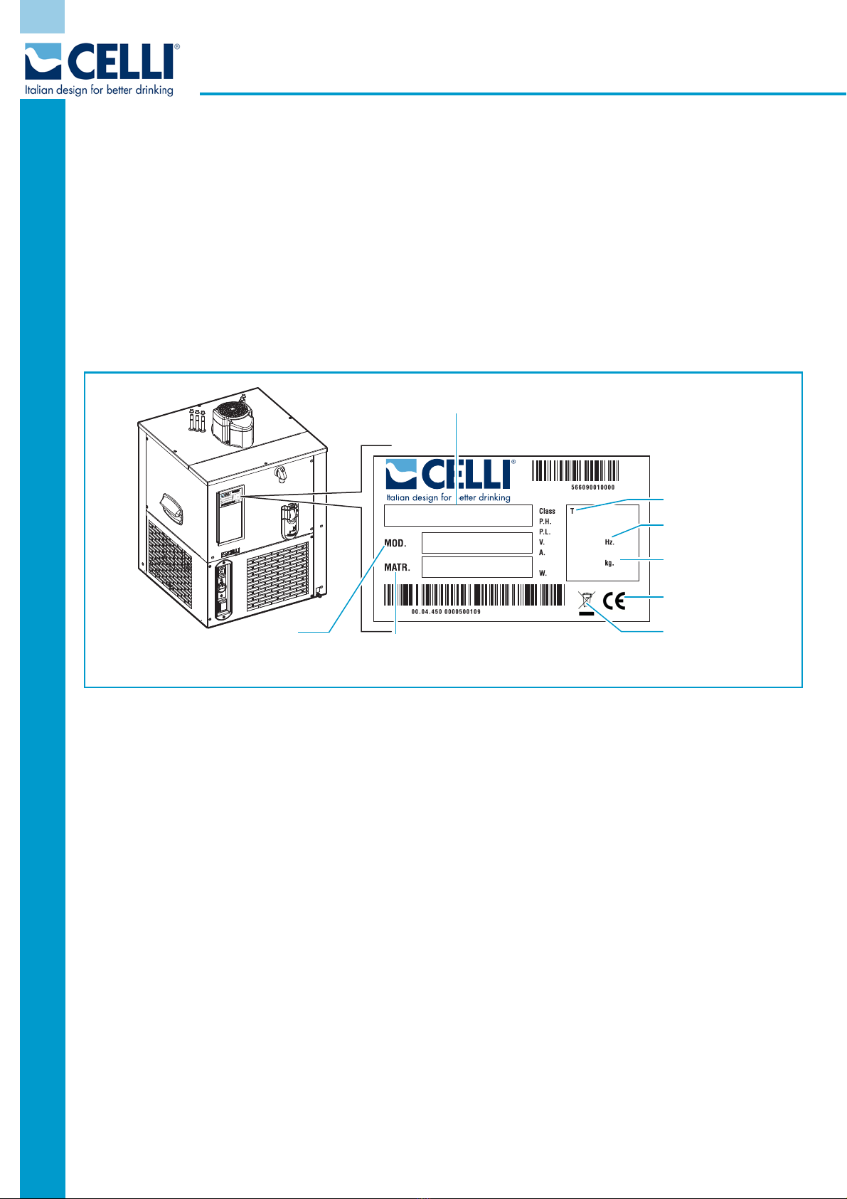
2.2 Machine identification......................................................................................................... 8
2.3 Warranty........................................................................................................................... 8
2.4 Symbols used in the manual ............................................................................................... 9
2.5 Staff qualification............................................................................................................... 9
3 - Description of the machine .................................................................................. 10
3.1 Main components of the TE/L Range with mechanical thermostat.........................................11
3.2 Main components of the TE15/L Range with mechanical thermostat .....................................13
3.3 Main components of the TE/L Range with electronic thermostat ...........................................15
3.4 Main components of the TE/L Range with digital thermostat ................................................17
3.5 Main components of the TE/L Range with water-cooled condensing .....................................19
3.6 Operating principle............................................................................................................21
3.6.1 Water stirring and recirculation..................................................................................22
3.7 Unit with electronic thermostat ..........................................................................................22
3.8 Unit with digital thermostat to function with glycol ..............................................................23
3.8.1 To obtain an ICE effect on the towers........................................................................23
3.8.2 ICE tower connection diagram - TE Glycol ..................................................................24
3.8.3 To dispense extra cold beer ......................................................................................25
3.8.4 Diagram with primary and secondary cooler for extra COLD beer .................................26
3.8.5 To obtain the ICE effect on the towers and dispense extra COLD beer .........................26
3.9 Water cooled condensing unit ............................................................................................27
3.10 Technical data ................................................................................................................29
3.10.1 Sound emissions.....................................................................................................29
3.11 Dimensions in mm (inches)..............................................................................................30
3.11.1 TE15/L...................................................................................................................30
3.11.2 TE25/L...................................................................................................................30
3.11.3 TE35/L...................................................................................................................30
3.11.4 TE50/L...................................................................................................................31
3.11.5 TE65/L...................................................................................................................31
3.12 Differential-switch power cord (optional)...........................................................................32
4 - Installation ........................................................................................................... 33
4.1 Checks and Unpacking ......................................................................................................33
4.2 Positioning .......................................................................................................................34
4.3 Environmental conditions...................................................................................................35
4.4 Electrical requisites ...........................................................................................................35
4.5 Connections .....................................................................................................................36
4.5.1 Preparing the machine..............................................................................................36
4.5.2 Connection to the drinks kegs ...................................................................................37

2
Rev. 12/17
TE15 - TE25 - TE35 - TE50 - TE65/L
PRE-MIX
4.5.3 Connecting the recirculation lines .............................................................................. 37
4.5.4 Connecting the python ............................................................................................. 38
4.5.5 Connecting the carbon dioxide CO2 (N2 for wine) ...................................................... 39
4.5.6 Electrical connection................................................................................................. 42
4.6 Adjusting the carbon dioxide (CO2) and nitrogen (N2) ......................................................... 43
4.7 Checking for leaks ............................................................................................................ 44
5 - Using the machine ............................................................................................... 45
5.1 Start-up........................................................................................................................... 45
5.2 Setting the temperature.................................................................................................... 46
5.3 Stopping the machine ....................................................................................................... 46
6 - Maintenance......................................................................................................... 47
6.1 Routine maintenance........................................................................................................ 47
6.2 Table of procedures.......................................................................................................... 48
6.3 Replacing the steel kegs ................................................................................................... 49
6.4 Replacing a carbon dioxide (CO2) or nitrogen (N2) bottle..................................................... 50
6.5 Cleaning the tap spout ..................................................................................................... 50
6.6 Cleaning the capacitor ..................................................................................................... 51
6.7 Sanitisation of undercounter premix system beverage lines ................................................. 52
6.7.1 How to sanitise the premix system lines .................................................................... 53
6.7.2 Regular cleaning of the taps (pre-mix systems).......................................................... 54
6.8 Replacing the water in the tank .........................................................................................55
6.9 Rinsing out the beer lines ................................................................................................. 57
6.10 Extraordinary maintenance..............................................................................................58
7 - Troubleshooting................................................................................................... 59
8 - Additional instructions......................................................................................... 63
8.1 Waste disposal ................................................................................................................. 63
8.2 Dismantling of the machine............................................................................................... 63
8.3 Disposal of electronic equipment (WEEE directive).............................................................. 64
9 - Annexes ............................................................................................................... 65
9.1 TE/L Range electrical diagram
Version with mechanical thermostat ........................................................................................... 65
9.2 TE/L Range electrical diagram
Version with electronic thermostat.............................................................................................. 66
9.3 TE/L Range electrical diagram
Version with digital thermostat................................................................................................... 67
9.4 TE/L Range electrical diagram
Version with water-cooled condensing ........................................................................................ 68

Safety
3
TE15 - TE25 - TE35 - TE50 - TE65/L
PRE-MIX
1 - Safety
Do not allow anyone to operate the machine unless suitably trained.
Keep the machine in good working order and do not allow any modifications to be made to it unless these
have been authorised by the manufacturer.
Before using the machine, read this section of the manual carefully; it instructs operators in the correct use of
the machine, and warns of improper use which may be hazardous.
1.1 Intended use
The PRE MIX system is used to cool and dispense cold pre-mix drinks.
The machines described in this manual are used to cool and dispense pre-mix drinks.
This appliance is intended to be used in defined "household and similar" applications such as:
- Holiday cottages and clients in hotels, motels and other residential type environments;
- Bed and breakfasts;
- Catering and applications other than retail or similar.
1.2 Improper use
These machines are designed for the use and conditions envisaged in this manual, in compliance with
Machine Directive 2006/42/EC.
The use of the dispensers for any purposes other than those for which they were designed is not allowed,
under any circumstances. Likewise, their use in any way other than that indicated in this manual is forbidden.
This unit can be used by adults without any experience and knowledge under supervision or after they have
been given instructions on the safe use of the appliance and have understood the risks. Children should not
play with the appliance. Cleaning and user maintenance must not be carried out by children.
This appliance is not intended for use by persons (including children) with reduced physical, sensory or
mental capabilities, or lack of experience and knowledge, unless they have been given supervision or
instruction concerning use of the appliance by a person responsible for their safety. Children should be
supervised to ensure that they do not play with the appliance
For the purposes of machine safety, and in accordance with the current legislation, any repair operations on
the machines must be carried out by the Service Centre.
• Do not alter or tamper with the internal dispenser components; if they do not work well, contact the
Service Centre.
• Do not place anything on top of the dispensers.
• Do not place the dispensers on top of any other object.
• Do not use liquids other than those indicated.
• If you believe the dispenser to be damaged, contact the Service Centre.
• Do not store explosive substances in this equipment, such as aerosol cans with a flammable propellant.

Safety
4
Rev. 12/17
TE15 - TE25 - TE35 - TE50 - TE65/L
PRE-MIX
1.3 List of hazards
The following list of hazards draws attention to safety aspects which must be considered at all times by
anyone using the machine.
DANGER
CO2 (CARBON DIOXIDE)
CO2 bottles must always be stored in a well-ventilated place where the air can flow in and out.
Great care must be taken to prevent CO2 leaks throughout the system, including the gas bottles.
If a CO2 leak is suspected, especially in a small area, ventilate the contaminated area at once.
Persons exposed to high concentrations of CO2 will experience trembling, swiftly followed by
unconsciousness and suffocation.
DANGER
MAINS ELECTRICITY
Always disconnect the machine from the electricity supply before doing any work on it, to prevent
damage and health hazards.
DANGER
GAS CYLINDER POSITION
To prevent the risk of injury or damage, the CO2 bottle must always be kept in a vertical position
against a wall, held in place by a chain fixed to a bracket.
Do not expose the bottle to heat sources or very low temperatures.
If a disposable CO2 bottle is used, secure it vertically to prevent it from falling or overturning.
DANGER
REFRIGERANT
The refrigerant used is R290 or R134a. To verify which refrigerant is used, refer to the
compressor label inside the machine, and the nameplate.
In the case of R290 refrigerant, this is a natural gas with a high degree of environmental
compatibility, but it is also combustible. During the transport and installation of the machine, be
careful not to damage any part of the refrigerating circuit.
If the refrigerant spurts out, it may catch fire or cause injury to the eyes. If you notice a leak, do
not take any naked flames or potential ignition sources near the machine; air the room for a few
minutes.
CAUTION
Keep the ventilation openings on the machine and on the cabinet in which the system is housed,
free from obstruction.

Safety
5
TE15 - TE25 - TE35 - TE50 - TE65/L
PRE-MIX
WARNING
REFRIGERANT
To avoid the formation of an inflammable mix of gas and air in the event of a leak in the
refrigerating circuit, the size of the room where the machine is located will depend on the
amount of refrigerant used.
Never switch the machine on if you notice any trace of damage. If you have any doubts, please
contact CELLI S.p.A.
The room must measure at least 1 m3. for every 8 gr. of R290 refrigerant used in the machine.
The amount of refrigerant in the machine is shown on the nameplate.
WARNING
AUTHORISED TECHNICAL STAFF
Only technical staff skilled in the electric, hydraulic or refrigeration field may carry out work on
the machine. All wiring and plumbing components must comply with national and local legal
requirements (when replacing components, use only genuine parts certified by CELLI S.p.A.).
CAUTION
ELECTRICAL REQUISITES
The electrical circuit must be correctly earthed and connected by means of a suitable differential
safety breaker.
CAUTION
PLUG SUPPLIED
Connect the machine to the electricity mains using the plug provided.
If you need to replace the plug, use an equivalent model type-approved for the country of use.
CAUTION
SANITISATION
Before sanitising the machine, carefully read the instructions given by the sanitisation product
manufacturer and put on all the necessary personal protective equipment (gloves, masks, etc.).
Ensure that the premises are well ventilated.
The sanitisation operations should only be carried out by specialised technical assistance
personnel.
CAUTION
LOW TEMPERATURE
If the machine is exposed to temperatures lower than 0°C, the water inside could turn to ice and
damage the machine.

Safety
6
Rev. 12/17
TE15 - TE25 - TE35 - TE50 - TE65/L
PRE-MIX
CAUTION
DRINKS CONTAINED IN PRESSURISED KEGS
To avoid any harm to people or damage to property, do not remove the cover from the keg until
you have discharged the CO2 pressure inside.
WARNING
REPLACEMENT OF THE POWER CABLE
If the power cable is damaged, it must be replaced by the manufacturer or their assistance
service or a similarly qualified person in order to prevent any possible risk.
1.4 Residual risks
During regular operating conditions the machine is safe. There are still residual risks, listed in the hazard list,
which are reduced if the machine is used correctly and according to the instructions given in the user’s
manual.

General information
7
TE15 - TE25 - TE35 - TE50 - TE65/L
PRE-MIX
2 - General information
The Use and Maintenance Manual is an integral and essential part of the machine and must be given to the
user. It must be kept in a safe place and read carefully, as it provides specific information concerning the
operation, maintenance and safety of the machine and of persons and/or objects that come into contact with
it.
If in doubt concerning the instructions supplied in the manual, contact CELLI S.p.A.
The manufacturer cannot be held liable, within or outside the terms of the contract, for any damage caused
by inappropriate machine installation and usage, or failure to observe the instructions provided.
The manufacturer reserves the right to modify the product and the relative technical documentation at any
time and without notification, and cannot be held liable for any errors or inaccuracies in the contents of this
manual.
This version of the Use and Maintenance Manual describes the characteristics of the standard production
machine as of the date of printing.
2.1 Manufacturer’s details
CELLI S.p.A.
Via Casino Albini, 605
47842 - S. Giovanni in Marignano - Rimini - Italy
Tel. (+39) 0541 755211 Fax (+39) 0541 759735
www.celli.com
Contact CELLI S.p.A. for any technical queries or to order spare parts.
When replacing machine parts, you are advised to use original spare parts; the manufacturer cannot be held
liable for any reduction in machine performance or damage caused by the use of non-original parts.
This manual refers to the standard version of the machine.
Non-standard machines may display minor differences not described in this manual.
If you have any doubts, please contact CELLI S.p.A.

General information
8
Rev. 12/17
TE15 - TE25 - TE35 - TE50 - TE65/L
PRE-MIX
2.2 Machine identification
This manual refers to the following machines:
TE/L PRE-MIX UNDERCOUNTER range
Models: - TE15
- TE25
- TE35
- TE50
- TE65
Make sure that the machine delivered to you carries the nameplate (EC nameplate) shown below:
This indicates the model, the serial number and all the machine technical data necessary for ordering spare
parts or reporting technical problems to the technical support service.
2.3 Warranty
For the warranty terms, please refer to the general conditions of sale in the CELLI S.p.A. price list.
TE
TE PRE MIX
TE0010
MODEL
MODEL
CODE MACHINE SERIAL
NUMBER
CLIMATE CLASS
ELECTRICAL
REQUISITES
TYPE AND WEIGHT OF
REFRIGERANT GAS
WASTE DISPOSAL
EC

General information
9
TE15 - TE25 - TE35 - TE50 - TE65/L
PRE-MIX
2.4 Symbols used in the manual
The manual uses the following safety symbols to draw the operator's attention to all operations which must
be strictly observed in order to prevent injury to persons or damage to the machine.
DANGER
Indicates the existence, on or around the machine, of a real risk of death or severe injury for the
operator and other persons; it is therefore essential to take the greatest care and proceed with
the greatest caution.
WARNING
Indicates the existence, on or around the machine, of a potential risk of death or severe injury
for the operator or other persons; it is therefore essential to take great care and proceed with
the greatest caution.
CAUTION
Indicates the existence, on or around the machine, of a potential risk of minor injury for the
operator or other persons; it is therefore essential to take great care and proceed with the
greatest caution.
2.5 Staff qualification
To ensure that all works performed on the machine are carried out in conditions of safety, the operators
must have the qualifications and meet the requirements for performing the tasks assigned.
The operators are classified as follows:
SPECIALISED MAINTENANCE TECHNICIAN
Operator qualified to perform complex operations in particular situations.
This is an operator properly trained through specific activities.
MACHINE OPERATOR
Non qualified operator or operator without specific skills, assigned to perform only simple tasks
or to use the machine by means of the controls of the same and to carry out simple cleaning and
replacement of products, following the instructions in this user’s manual when using the
machine.
He/she cannot carry out the operations assigned to specialised maintenance operators.
The symbol at the beginning of each section indicates the staff authorised to perform the operations
described.

Description of the machine
10
Rev. 12/17
TE15 - TE25 - TE35 - TE50 - TE65/L
PRE-MIX
3 - Description of the machine
The TE/L range of machines (mod. 15 - 25 - 35 - 50 - 65) are coolers that dispense premix drinks
contained in suitable containers (kegs).
This manual refers to the TE/L PRE-MIX UNDERCOUNTER range of machines.
They allow the dispensing of:
- cold pre-mix drinks.
The drinks are cooled by a cooling unit within the machine. The drinks are carried - via thermally insulated
plastic tubes - to the dispensing tower. The insulating tube (known as the “python”) and the dispensing tower
are not included with the machine.
"Pre-mix drinks" means drinks that are ready for consumption, without needing any further additions or
mixing.
Beer, soft drinks and wine are all typical pre-mix drinks.

Description of the machine
11
TE15 - TE25 - TE35 - TE50 - TE65/L
PRE-MIX
3.1 Main components of the TE/L Range with mechanical thermostat
3
4
8
5
6
1
2
7
16
17
18
19
12
13
14
9
10
11
15
TE0020

Description of the machine
12
Rev. 12/17
TE15 - TE25 - TE35 - TE50 - TE65/L
PRE-MIX
1 -
UPPER COVER
2 -
RECIRCULATION PUMP
3 -
COILS
4 -
BRACKET FOR THERMOSTAT CAPILLARY TUBE
5 -
EVAPORATOR
6 -
INSULATING TANK
7 -
SIDE PANEL
8 -
DRAINAGE FOR TANK EMPTYING
9 -
FAN UNIT
10 -
CONDENSER
11 -
DEHYDRATOR FILTER
12 -
ON/OFF LIGHT SWITCH
13 -
THERMOSTAT ADJUSTMENT KNOB
14 -
RECIRCULATION PUMP SOCKET
15 -
MECHANICAL THERMOSTAT
16 -
FRONT/SIDE PANEL
17 -
OVERFLOW DRAINAGE
18 -
COMPRESSOR
19 -
REAR PANEL

Description of the machine
13
TE15 - TE25 - TE35 - TE50 - TE65/L
PRE-MIX
3.2 Main components of the TE15/L Range with mechanical thermostat
3
4
8
9
10
11
5
6
2
7
18
17
19
14
1516
13
12
1
TE0370

Description of the machine
14
Rev. 12/17
TE15 - TE25 - TE35 - TE50 - TE65/L
PRE-MIX
1 -
UPPER COVER
2 -
RECIRCULATION PUMP
3 -
COILS
4 -
BRACKET FOR THERMOSTAT CAPILLARY TUBE
5 -
EVAPORATOR
6 -
INSULATING TANK
7 -
FAN UNIT
8 -
DEHYDRATOR FILTER
9 -
CONDENSER
10 -
FRONT/SIDE PANEL
11 -
OVERFLOW DRAINAGE
12 -
DRAINAGE FOR TANK EMPTYING
13 -
MECHANICAL THERMOSTAT
14 -
ON/OFF LIGHT SWITCH
15 -
THERMOSTAT ADJUSTMENT KNOB
16 -
RECIRCULATION PUMP SOCKET
17 -
COMPRESSOR
18 -
REAR PANEL
19 -
SIDE PANEL

Description of the machine
15
TE15 - TE25 - TE35 - TE50 - TE65/L
PRE-MIX
3.3 Main components of the TE/L Range with electronic thermostat
3
5
8
6
1
2
7
15
16
17
18
12
13
9
10
11
14
4
TE0060

Description of the machine
16
Rev. 12/17
TE15 - TE25 - TE35 - TE50 - TE65/L
PRE-MIX
1 -
UPPER COVER
2 -
RECIRCULATION PUMP
3 -
COILS
4 -
BRACKET FOR THERMOSTAT SENSOR
5 -
EVAPORATOR
6 -
INSULATING TANK
7 -
SIDE PANEL
8 -
DRAINAGE FOR TANK EMPTYING
9 -
FAN UNIT
10 -
CONDENSER
11 -
DEHYDRATOR FILTER
12 -
ON/OFF LIGHT SWITCH
13 -
RECIRCULATION PUMP SOCKET
14 -
ELECTRONIC THERMOSTAT
15 -
FRONT/SIDE PANEL
16 -
OVERFLOW DRAINAGE
17 -
COMPRESSOR
18 -
REAR PANEL

Description of the machine
17
TE15 - TE25 - TE35 - TE50 - TE65/L
PRE-MIX
3.4 Main components of the TE/L Range with digital thermostat
5
7
8
1
2
3
4
6
9
17
16
18
19
14
13
10
11
12
15
TE0130

Description of the machine
18
Rev. 12/17
TE15 - TE25 - TE35 - TE50 - TE65/L
PRE-MIX
1 -
UPPER COVER
2 -
INSULATING SEAL
3 -
RECIRCULATION PUMP
4 -
RECIRCULATION PUMP INSULATION
5 -
COILS
6 -
BRACKET FOR THERMOSTAT SENSOR
7 -
EVAPORATOR
8 -
INSULATING TANK
9 -
SIDE PANEL
10 -
FAN UNIT
11 -
CONDENSER
12 -
DEHYDRATOR FILTER
13 -
RECIRCULATION PUMP SOCKET
14 -
ON/OFF LIGHT SWITCH
15 -
DIGITAL THERMOSTAT
16 -
DRAINAGE FOR EMPTYING AND LEVEL CHECK
17 -
FRONT/SIDE PANEL
18 -
COMPRESSOR
19 -
REAR PANEL
This manual suits for next models
4
Table of contents