CELLKIT 909 series User manual

USER GUIDE
FOR : 909 Series

Thank you for purchasing the CELLKIT 909 series SMD Rework Soldering station. Please read this
manual before operating this repair tools. Store the manual in a safe, easily accessible place for future
reference.
This CELLKIT 909 series is combination of 850 series, 936 series and DC Power Supply.
Precautions
In the instruction manual, "Warning" and "Caution" are defined as follows.
WARNING : Misuse may potentially cause death of or serious injury to, the user.
CAUTION : Misuse may potentially cause injury to the user or physical damage to the objects
involved. For your own safety, be sure to comply with these precautions.
Package list
Please check and confirm the following items in the package when you purchase
Item Quantity
909 Station 1
Soldering tip 1
Soldering tip stand 1
Sponge for cleaning is included 1
Holder for handle of hot air soldering head 1
Examination Line 1
User Guide 1
1. Shell of the machine
2. Switch of air control
3. Air flow indicator
4. Switch of temperature control
5. Indicator of temperature
6. Switch for temperature setting of the tip
7. Indicator of the tip
8. Plug of the tip
9. Handle of the hot air gun
10.Handle of the tip
11. Sponge for cleaning of the tip
12.Stand for the tip
13.Hot air welding head for removal
14.Power switch for the direct current 20.Direct current electric current form
15.Power switch for the tip 21.The direct current electric voltage outputs to
16.Holder for the handle of the soldering head connect
17.Power for the tip 22.The direct current power supply instructions light
18.Direct current electric voltage control knob 23.Examination line
19.Direct current electric voltage form
Name of Part
A. Instruction To Working With ‘Rework Station’
WARNING
1. Heat protector. For safety, the power will automatically shut off when the temperature in high enough
and will be on again when the temperature is safe. Switch the power on to cool down the hot air head,
lower down the set temperature or increase the air flow to continue working.
This User Guide is divide into 3 section, A (
Working With ‘Soldering Station’), and C (Instruction To Working With ‘DC Power Supply’)
Instruction To Working With ‘Rework Station’), B (Instruction To

You must shut off the power when:
?The temperature protector is in trouble
?You don't want to continue the work
?You want to leave the station.
2. Be careful. It is high temperature. Never use this rework station when it is close to flammable gas or
other material like paper. Both the nozzle and the air are in high temperature. Never touch the hot
nozzle or blow the body skin directly. It smokes a little bit when you switch on power. But after a while
the smoke will disappear.
3. After you shut the station off, it will cool down automatically. When temperature decrease to 50°C, it
will stop. During this time, don't unplug the plug.
4. Dropping down or shaking violently.
Heating tube contains quartz. Dropping down or shaking violently would break the glass.
5. Don't dismantle the pump.
6. If the machine will mot be used for along time, unplug the plug. If the machine if plugged, there will be
some current input even if it is switched off.
7. Advise other people in the work area that the unit can and should be considered potentially
dangerous.
CAUTION
1. Before use pump securing screw (M5*10) under the base of the soldering station must be removed.
Otherwise it will cause serious problem.
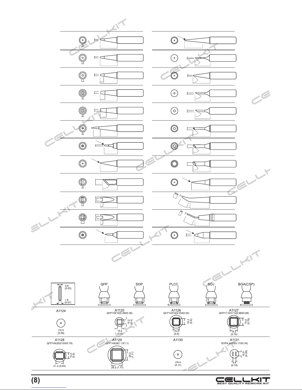
2. Select the nozzle in comploiant with the size of integrated circuit unit. When both the heater and the
nozzle are cool, install the nozzle if one of them is still hot, installation should be done after it is cool for
safety of people.
3. Before use please read the User Guide in detail.
4. Before use please joint the wire connected with ground which is used to avoid transmitting static.
5. Don't damage the piece against removal. Otherwise the guaranteed w service will be invalid.
6. It is forbidden to put other metal articles in the net hole on the top of the soldering iron. This action will
damage the heating installation and make people get an electric shock.
7. When in case the soldering station cannot work normally because of fault, please contact with
supplier. Before transportation, Please lock well the red screw under the base of the rework station.
Applications:
?It is suitable for disassembling soldering for the most of part an the surface for example SOIC, CHIP,
QFP, PLCC, BGAand so on
?It is suitable for contractive flexible tube.
?Design of static electricity proof: prevent from damaging PCB caused by static electricity and creepage.
?Adapting soldering methods that unnecessary touching soldering joint, it can avoid the elements
displacement from heat shocking.
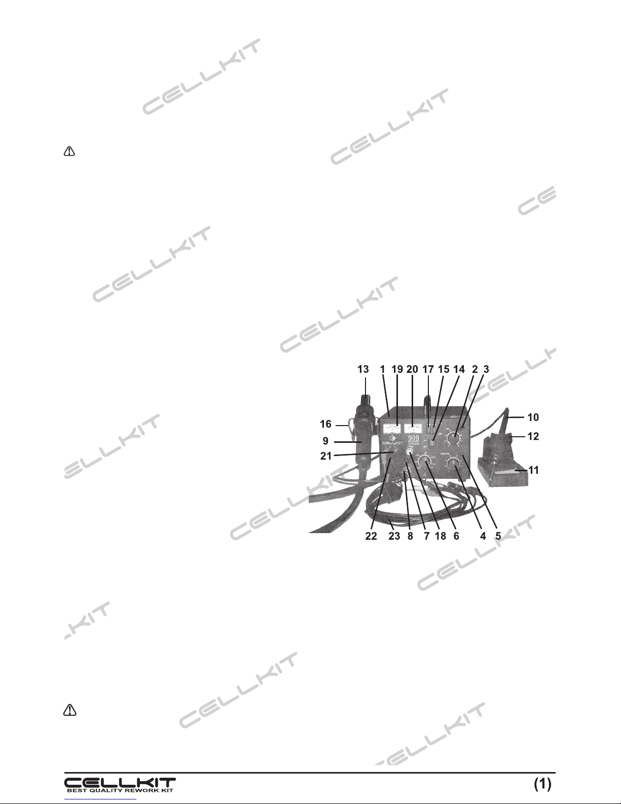
1. Installation of the nozzle
1. Release the screw of the nozzle.
2. Insert the nozzle into position and fasten the screw.
Don't install the nozzle with too much strength, neither installs it pulling the edge with a force, nor too
much strength to drive the screw.
2. Setting up & Operating the 909
2.1. QFP tin removal process
1. Plug for power
2. Switch on the power

Afet the power is switched on, the gun will blow air and the heating material will start heating.
3. Adjust the air-blow and the switch of the temperature control (see: Temperature Chart)
We suggest to adjust the temperature between 250-350°C. When the indicator flicks, it means the
temperature has reached the set. For air blow control, if it is single nozzle, you can set it at 1-3 shift and
other nozzle at 4-6 shift (But not blow the component off)
4. Install the puller under theIC (Integrated Circuit) unit.
If the with of the unit is not compliant with the size of the wire, you, depress the wire for installation.
5. Melt the soldering material
Hold the soldering head, aim at the soldering material. The hot air will melt the soldering material. Don't
touch the line of the IC with the nozzle.
6. Remove the IC
When the soldering material melted, remove the IC unit away.
7. Switch off the power
After you switch off the power, the auto air - blow function will be actuated. Cool air will be delivered
through the tube for cooling the heating material and the handle. So don't unplug the plug during this
time. If you don't use the machine for along time later, unplug the plug.
8. Removal the superabundant soldering material.
After removal of the integrated unit, the superabundant soldering material could be taken away by the
cleaner.
NOTE: if it is SOP; PLCC, you can lift the integrated unit with a clip.
2.2. QPF soldering
1. Coat with some soldering paste, and put the SMD on the circuit unit.
2. Pre - heat the SMD.
3. For soldering spray hot air to the line frame.
4. After soldering, clean the superabundant soldering material.
WARNING: To solder with hot air is effective. But it may cause soldering material ball of cause
connection of the material. We suggest you to check the soldering unit carefully.
3. Replace The Heating Material
1. Release the screw and take out the heating unit. Release 3 screws in the handle (see fig. 1-1,2,3) and
release the heating material.
2. Open the handle.
Release the termination of the ground connection (see fig. 2-1) and take out the tube. There is quartz
glass and isolation material inside. Don't drop them or get them lost.
3. Take out the heating material.
Release the inserted termination (see fig. 2-2) and take out the heating material.
4. Insert new heating material.
Install it carefully, don't scratch the heating material. Assemble the handle in reverse process when
open it. Insert the rise high part into the tube.

1
2
3
fig. 1 fig. 2
1
2
4. Heating Unit Demonstration
5. Temperature Chart:
Classification of measurement: (A1124) 3 mm to the air - blow no is measured by a recorder.
The room temperature is 23°C.
The diameter ofA1124 single tube is 2.5 (0.09 inch)
Note:
1, 4, 6, 8 : the air-blow
600
400
200
02 4 6
14
6
8
Time (minutes)
o
Temperature ( C)
Switch Control Temperature
B. Instruction To Working With ‘Soldering Station’
When the power is on, the tip temperature is between 200ºC / 392ºF and 480ºC/896ºF. Since mishandling
may lead to burns or fire, be sure to comply with the following precautions.
?Do not touch the metallic parts near the Tip.
?Do not use the product near flammable items.
?Advise other people in the work area that the unit can and should be considered potentially dangerous.
?Turn the power off while taking breaks and when finished using the unit.
?Before replacing parts or storing the unit, turn the power off and allow the unit to cool to room
temperature.

To prevent damage to the unit and ensure a safe working environment, be sure to comply with the following
precautions.
?Do not use the unit for applications other than soldering.
?Do not rap the soldering iron against the work bench to shake off residual solder, or otherwise subject
the iron to severe shocks.
?Do not modify the unit.
?Use only genuine replacement parts.
?Do not wet the unit or use the unit when your hands are wet.
?The soldering process will produce smoke, so make sure the area is well ventilated.
?While using the unit, don't do anything which may cause bodily harm or physical damage.
The sponge is compressed. It will swell when moistened with water. Before using the until, dampen the
sponge with the water and squeezed it dry. Failure to do so may result in damage to the soldering tip.
Note: The iron receptacles for each soldering irons are different. Be sure to use the proper one for each
type of soldering iron. (Refer to Parts List.)
1.2. Connection Solder 936 to Station
Be sure to turn off the power switch before connecting or disconnecting the soldering iron. Failure to do so
may damage the P.W.B.
1. Connect the cord assembly to the receptacle.
2. Place the soldering iron in the iron holder.
3. Plug the power cord into the power supply. Be sure to ground the unit.
1.3. Set the Temperature
When the temperature rises to the set, the indicator of the heater will flash, indicating you can start
soldering. When you are not using the soldering tip, it should be put on the stand.
2. Tip Care and Use
vTip Temperature
High soldering temperatures can degrade the tip. Use the lowest possible soldering temperature.
The excellent thermal recovery characteristics ensure efficient and effective soldering even at low
temperatures. This also protects the soldered items from thermal damage.
vCleaning
Clean the tip regularly with a cleaning sponge. As oxides and carbides from the solder and flux can
form impurities on the tip. These impurities can result in defective joints or reduce the tip's heat
conductivity. When using the soldering iron continuously, be sure to loosen the tip and remove all
oxides at least once a week. This helps prevent seizure and reduction of the tip temperature.
vWhen Not in Use
Never leave the soldering iron sitting at high temperature for long periods of time, as the tip's solder
plating will become covered with oxide, which can greatly reduce the tip's heat conductivity.
vAfter Use
Wipe the tip clean and coat the tip with fresh solder. helps prevent tip oxidation.
1. Setting up & Operating Soldering Iron
1.1. Iron Holder

3. Inspect and Clean the Tip
1. Set the temperature to 250°C (482°F)
2. When the temperature stabilizes, clean the tip with the cleaning sponge and check the condition of
the tip.
3. If there is black oxide on the solder-plated portion of the tip, apply new solder (containing flux and
wipe the tip on the cleaning sponge. Repeat until the oxide is completely removed. Coat with new
solder.
4. If the tip is deformed or heavily eroded, replace it with a new one.
5. Never file the Tip to remove oxide.
4. Adjust The Temperature Of The Tip
After you replace the iron tip or heater, the temperature should be adjusted again. The temperature of the
tip is different from the type due to conduction and release of heat. Please see the following chart for the
difference.
C. Instruction To Working With ‘DC Power Supply’
WARNING : Please make sure to set correct VOLTAGE, according to mobile phone battery or other
appliance Voltage Capacity. Over Voltage could damage mobile phone or other
appliance.
?Firstly, make sure voltage from the mobile phone or appliance
?Turn on, the power supply then choose the right voltage from the panel, it has tuning/ adjustment knob
to select right voltage from 0 – 15 V.
?Plug the black (-) and red (+) connector to the power supply output as indicate by color.
?Turn off the power supply, and then put the connector to the mobile phone or appliance with the same
pole for position black as negative pole and red as positive pole.
?Turn on the power supply, and then start the mobile phone or appliance.
?To disconnect between power supply with the mobile phone or appliance, please turn off the power
supply first.After that, disconnect the connection cable with the mobile phone or appliance
Note: Some mobile phone like, Nokia, need ground connection to start it. The ground connector as
indicate with green or yellow connector. If green connector cannot be used, try the yellow connector.
2. Maintenance
1. The fuse substitution.
If the fuse burns breaking, voltage regulation or the protection pilot lamp goes out and this power supply
stop work. The most before all others fuse found burns the cause breaking, then according to the model
substitution the fuse.
2. Please don't be used in the place that the environment temperature is more than 40°C. The instrument
should stay the space that is enough at the back during the use and dissipates heat in order to be of
advantage to.
3. Accurately adjust before this power supply leaves the factory, and does not adjust machine's circuit
parameter, at will in order to avoid the influence precision.
1. Setting up & Operating DC Power Supply

Hot air soldering station Specification
Specified voltage 220V/AC
Consumption 270W
Type of pump Membran
Air flow 0.3-24L/min. Dapat diatur
pump power 45W
Heater 250W logam
o
Hot air temp. 100-420 C.
Soldering station Specification
Power 60W
Output Voltage 24V / AC
o
Temp. Range 200-480 C.
Bulk 187mm X 135mm X 245mm
Weight 4 kg
DC power supply Specification
Input voltage (AC) 220V±10%
Frequency 50/60 Hz
Output voltage (DC) 0-15V
Output current 0-1A (lo max=1A)
Overload protection pickup current >= 1A
Specification*
* Specification is subject to change without notice due to improvement
Operation Condition DC Power Supply
o o
Temperature range -10 C - 40 C
Relative humidity < 90% < 80%
Working Condition Storage Condition
o o
-20 C - 80 C
Voltage stability <= 0.01% +/- 2mv
Load stability <=1%
Groove 0.5m Vrms (5 Hz-1Mhz,Iomax>1A)
Temperature coefficient <=300ppm/'C

25 (0.98)
17 (0.68)
15 (0.8)
19 (0.74)
14 (0.55)
17 (0.68)
15 (0.6)
15 (0.6)
17 (0.68)
17 (0.68)
17 (0.68)
15 (0.6)
900M-T-LB
900M-T-I
900M-T-S4
900M-T-H
900M-T-1.8H
900M-T-0.8C
900M-T-0.5C
900M-T-1C
900M-T-2C
900M-T-3C
900M-T-4C
O O
-10 C/-18 F
O O
-10 C/-18 F
O
0 C
O O
-20 C/-36 F
O O
-20 C/-36 F
O O
-10 C/-18 F
O
0 C
O
0 C
O
0 C
O
0 C
O
0 C
O
0 C
RO.5 (0.08)
RO.2 (0.008)
RO.25 (0.01)
(0.02)(0.4)(0.08)
(0.1)
(0.08) (0.18) (0.4) (0.031)
Æ0.5Æ1Æ2Æ3
Æ2Æ4Æ1Æ0.8
O
45
O
60
O
45
O
45
O
45
O
60
O
45
O
900M-T-1CF
O
900M-T-2CF
O
900M-T-3CF
O
900M-T-4CF
O
900M-T-1.5CF
O
25
O
25
7 5.
7 5
.
(0.29)
(0.29)
1.2 (0.04)
1(0.04)
0 1 )3.5 ( . 3
. 0 0 )
1 8 ( . 7
17 (0.68)
17 (0.68)
15 (0.5)
17 (0.68)
17 (0.68)
(0.031)
Æ0.8
0.6 (0.024)
900M-T-0.8D
900M-T-B
900M-T-K
900M-T-R
900M-T-RT
O
0 C
O
0 C
17 (0.68)
17 (0.68)
17 (0.68)
17 (0.68)
25 (0.98)
14 (0.55)
13 (0.51)
(0.047)(0.06)(0.09)(0.12)
(0.047)
(0.08)(0.2)(0.2)(0.17)
Æ1.2Æ1.6Æ2.4Æ3.2
Æ1.2
Æ2Æ5
Æ5.1Æ4.2
0.7 (0.028)
0.5 (0.02)
0.5 (0.02)
0.5 (0.02)
2 (0.03)
0.7 (0.028)
900M-T-1.2D
900M-T-1.6D
900M-T-2.4D
900M-T-3.2D
900M-T-1.2LD
900M-T-SB
900M-T-SI
O
0 C
O
0 C
O
0 C
O
0 C
O O
-10 C/-18 F
O O
+10 C/+54 F
O
0 C
O
0 C
O
0 C
O
0 C
3
5
6.5
(0.1)
(0.2)
(0.25)
RO.2 (0.008)
RO.2 (0.008)
RO.5 (0.02)
O
45
(0.08)
(0.08)
2
2
3.22
(0.1)(0.06)
Dimensions of renewable nozzles.
Indicate the flat IC dimension (…..).(mm).
TIPS

REPAIRING
BOARD SET
SOLDER 936
REPAIRING
MATERIALS
ULTRASONIC
CLEANER
BLOWER
HOT AIR GUN
SOLDER CS-30
POWER SUPPLY
SCREWDRIVER
PLIER &
TWEEZER
WORKING LAMP
BLOWER
INFRA RED
Table of contents