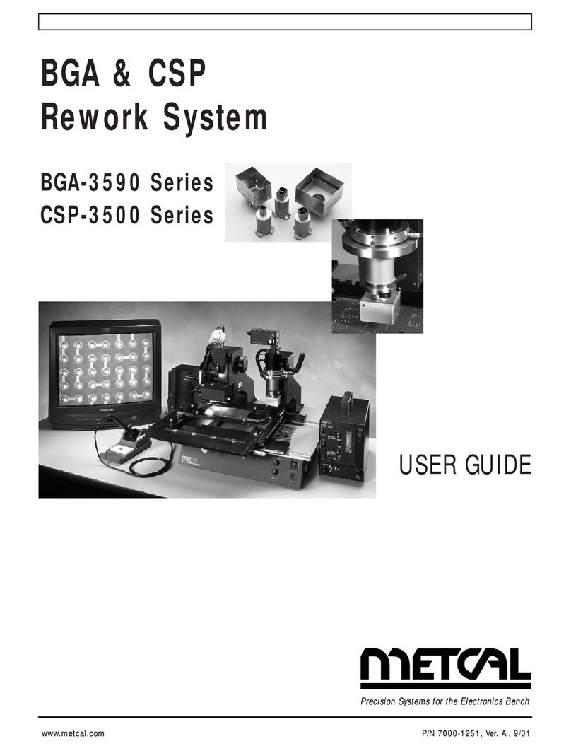
Metcal RSS-1000-CVSI User manual

USER MANUAL, RSS-1000-CVSI
7000-5970 Rev. A
page 1 of 396
Robotic Soldering System
RSS-1000-CVSI
User Manual

USER MANUAL, RSS-1000-CVSI
7000-5970 Rev. A
page 2 of 396
Copyright © 2018 OK International, Inc. 10800 Valley View Street, Cypress, CA 90630
Visit us on the web at www.okinternational.com/metcal
PROPRIETARY NOTICE: This document contains proprietary data of OK International, Inc. The
receipt or possession of this document does not convey any rights to reproduce it, disclose its
contents, or to manufacture the concepts and details disclosed by this document. This document
may not be copied or disclosed in whole or in part to anyone without written permission of an officer
of OK International, Inc.
All rights reserved.

USER MANUAL, RSS-1000-CVSI
7000-5970 Rev. A
page 3 of 396
Table of Contents
SAFETY AND REGULATORY INFORMATION............................................................................................. 7
WARNING ......................................................................................................................................................... 7
OTHER SAFETY TIPS .................................................................................................................................... 8
SPECIFICATIONS ............................................................................................................................................... 9
INTRODUCTION AND GENERAL OVERVIEW ........................................................................................... 12
SYSTEM ARCHITECTURE ............................................................................................................................. 13
TIPS BEFORE SETTING UP ........................................................................................................................... 15
UNBOXING INSTRUCTIONS .......................................................................................................................... 16
CONTROLLER BOX CONNECTIONS .......................................................................................................... 20
ROBOT BASE CONNECTIONS ..................................................................................................................... 21
ROBOT GANTRY CONNECTIONS ............................................................................................................... 22
ROBOT HEAD CONNECTION ........................................................................................................................ 22
CV POWER CABLE CONNECTION INSTRUCTIONS ........................................................................... 23
SOFTWARE NAVIGATION ............................................................................................................................. 24
LOGIN SCREEN ............................................................................................................................................ 24
MAIN SCREEN OVERVIEW ........................................................................................................................ 25
MAIN MENU BAR .......................................................................................................................................... 26
HEADER BAR................................................................................................................................................. 28
PROFILE OPTIONS ...................................................................................................................................... 31
ADVANCE PROFILE OPTIONS .................................................................................................................. 33
SOLDER FEEDER OPTIONS ...................................................................................................................... 35
CAMERA TOOLS ........................................................................................................................................... 37
CONNECTION VALIDATION DISPLAY ..................................................................................................... 39
TOOLBAR ....................................................................................................................................................... 43
MOTION CONTROL ...................................................................................................................................... 45
REMAINING MENUS/ BUTTONS ............................................................................................................... 48
SYSTEM OPERATION ..................................................................................................................................... 50
POWERING UP THE UNIT .......................................................................................................................... 50
POWERING OFF THE UNIT ........................................................................................................................ 51
REBOOTING SOFTWARE ........................................................................................................................... 54
LOGGING IN TO SOFTWARE .................................................................................................................... 57
UPDATING SOFTWARE .............................................................................................................................. 60
UPDATING USER MANUAL ........................................................................................................................ 65

USER MANUAL, RSS-1000-CVSI
7000-5970 Rev. A
page 4 of 396
SAFETY FEATURES .................................................................................................................................... 69
Z-LIMIT SAFETY ........................................................................................................................................ 69
CLEARANCE HEIGHT SAFETY............................................................................................................... 78
CONNECTION VALIDATION (CV) SAFETY FEATURES .................................................................... 82
CLEAR INDICATORS RADIO FREQUENCY IS ACTIVE ................................................................. 82
AUTOMATIC RF ACTIVATION/DEACTIVATION ............................................................................ 82
SAFETY COVER INSTALLATION & ACTIVATION ............................................................................. 84
COMPONENTS OF AC-RSS-1KSC ....................................................................................................... 85
SAFETY COVER INSTALLATION ....................................................................................................... 86
SAFETY COVER ACTIVATION ........................................................................................................... 98
CHANGING PASSWORD ........................................................................................................................... 102
ADDING NEW USER .................................................................................................................................. 106
DELETING USER ........................................................................................................................................ 112
VIEWING USER LOGIN HISTORY........................................................................................................... 116
CHANGING TIME ZONE ............................................................................................................................ 118
CLEAR PATTERN PARAMETERS ........................................................................................................... 122
RESET TO FACTORY SETTINGS ........................................................................................................... 126
IOT SETTINGS ............................................................................................................................................. 129
PROFILE MANAGEMENT .......................................................................................................................... 130
PROFILE CREATION ............................................................................................................................... 130
SAVING A PROFILE ................................................................................................................................ 131
SAVING PROFILE TO EXTERNAL USB DEVICE ............................................................................... 134
PROFILE REMOVAL................................................................................................................................ 136
FOLDER CREATION ................................................................................................................................ 140
FOLDER REMOVAL ................................................................................................................................ 146
CONNECTION VALIDATION VS STANDARD SOLDERING .............................................................. 150
WHY USE CONNECTION VALIDATION? ............................................................................................ 150
FLOW CHARTS OF SOLDERING PROCESSES .................................................................................... 150
CV TIP SELECTION ................................................................................................................................. 151
CV STATE CODES ................................................................................................................................... 151
SOLDER PARAMETERS AND SETTINGS ............................................................................................. 153
SOLDER POINT ........................................................................................................................................ 153
SOLDER LINE ........................................................................................................................................... 158
FEEDING SOLDER ................................................................................................................................... 163
SOLDER FEEDER SETTINGS ................................................................................................................. 164

USER MANUAL, RSS-1000-CVSI
7000-5970 Rev. A
page 5 of 396
WAY POINTS ............................................................................................................................................ 165
SOLDER WIRE FEEDER ADJUSTMENT ............................................................................................... 166
ADVANCED PROFILE FUNCTIONS ........................................................................................................ 168
EDIT PROFILE .......................................................................................................................................... 168
EDIT PROFILE OVERVIEW ................................................................................................................ 168
SOLDER PARAMETER EDIT .............................................................................................................. 170
PROFILE EDIT ...................................................................................................................................... 175
Edit Transition Speed .......................................................................................................................... 180
Edit Parameter ..................................................................................................................................... 182
Editing a Point Coordinate .................................................................................................................. 183
Editing Line Coordinates .................................................................................................................... 185
Editing Coordinates Using Record Coordinate Function ................................................................... 188
Editing Coordinates Using Offset All Function.................................................................................. 192
Editing Feeder Settings ....................................................................................................................... 197
Edit Order of Features Within a Profile .............................................................................................. 199
Remove a Feature from a Profile ........................................................................................................ 200
MERGE PROFILE ..................................................................................................................................... 201
COMPONENT BASED MERGE........................................................................................................... 201
PRINTED CIRCUIT BOARD ASSEMBLY BASED MERGE ............................................................ 208
GENERATE ARRAY ................................................................................................................................ 216
Examples of Generate Array Settings ..................................................................................................... 218
Single Point Array ................................................................................................................................... 229
Multiple Pattern Array ............................................................................................................................ 232
SET GO-TO LOCATION........................................................................................................................... 238
OFFSET PROFILE ..................................................................................................................................... 239
DRY RUN ................................................................................................................................................... 243
TIP ALIGNMENT .......................................................................................................................................... 245
TIP ALIGNMENT ...................................................................................................................................... 245
CENTER POINT ALIGNMENT ............................................................................................................... 248
CAMERA CALIBRATION & FUNCTIONS ............................................................................................... 256
CALIBRATION ......................................................................................................................................... 256
POSITION VERIFICATION TEST ........................................................................................................... 268
FINE ADJUSTMENT AFTER CAMERA CALIBRATION .................................................................... 270
TAKING A SCREENSHOT....................................................................................................................... 273
OPENING AN IMAGE/SCREENSHOT/ DXF/ GERBER ....................................................................... 277
USER MANUAL, RSS-1000-CVSI
7000-5970 Rev. A
page 6 of 396
IMAGE ZOOM ........................................................................................................................................... 278
ESTABLISHING FIDUCIAL POINTS (Future Feature, Not Present in this Release) ............................. 282
PATTERN RECOGNITION ...................................................................................................................... 286
Template Creation ................................................................................................................................... 287
Pattern Recognition Using Template ...................................................................................................... 289
Layout Creation ...................................................................................................................................... 305
Component Layout Creation ................................................................................................................... 311
Pattern Recognition Using Layout .......................................................................................................... 315
MECHANICAL ADJUSTMENT OF COMPUTER VISION CAMERA ................................................. 330
TIP CLEANING ............................................................................................................................................. 332
OVERVIEW ............................................................................................................................................... 332
TIP CLEANING PROFILE SET UP .......................................................................................................... 333
ADVANCE TIP CLEANING PROFILE ................................................................................................... 336
IMPLEMENTATION OF TIP CLEANING PROFILE ............................................................................. 341
TIP CLEANING TROUBLE SHOOTING ................................................................................................ 346
EDITING A CLEANING PROFILE .......................................................................................................... 347
CUSTOM CLEANING LOCATIONS ....................................................................................................... 354
BRUSH REPLACEMENT ......................................................................................................................... 356
INSTALLATION & USE OF FUME EXTRACTION & NITROGEN ......................................................... 359
FUME EXTRACTION .................................................................................................................................. 359
NITROGEN ................................................................................................................................................... 360
TROUBLESHOOTING .................................................................................................................................... 362
MAINTENANCE & INSPECTION ................................................................................................................. 367
REPLACING CV-H8-AV .............................................................................................................................. 369
CHANGING SOLDER WIRE FEEDER..................................................................................................... 381
REPLACING A FUSE .................................................................................................................................. 392
WHEN TO CHANGE SOLDERING CARTRIDGE .................................................................................. 396

USER MANUAL, RSS-1000-CVSI
7000-5970
Rev.
A
page
7
of
396
SAFETY AND REGULATORY INFORMATION
WARNING
IN ORDER TO BE IN COMPLIANCE WITH REQUIREMENTS OF CE DIRECTIVES, THE
ROBOTIC SOLDERING SYSTEM MUST BE EQUIPPED WITH THE AC-RSS-1KSC SAFETY
COVER ACCESSORY. THE SAFETY INTERLOCK OF THE ENCLOSURE WILL
AUTOMATICALLY CEASE ALL MOVEMENT AND HOME THE SYSTEM ONCE AN
OPERATOR COMES IN CLOSE PROXIMITY OF THE WORKING ENVELOPE.
THIS PRODUCT IS HIGH VOLTAGE! MAKE SAFETY THE NUMBER ONE PRIORITY
WHEN OPERATING THIS UNIT.
TO PREVENT FIRE OR SHOCK HAZARD, DO NOT EXPOSE SYSTEM TO MOISTURE OR
OPERATE UNIT WITH WET HANDS.
TO PREVENT FIRE OR SHOCK HAZARD, DO NOT USE FLAMMABLE SOLVENTS NEAR
OR ON THE SYSTEM WHILE CONNECTED TO A POWER SOURCE.
FAMILIARIZE ONESELF WITH EMERGENCY STOP BUTTON’S LOCATION AND HOW TO
USE IT.
TO PREVENT POSSIBILITY OF INJURY OR DAMAGE TO THE SYSTEM:
o DO NOT USE THE UNIT IF THERE ARE ANY VISIBLE BROKEN OR DAMAGED
WIRES/CABLES.
o DO NOT OPERATE WITH ANY COVERS OR PANELS REMOVED.
o DO NOT MOVE THE ROBOT IN ANY AXES BY HAND
o ALWAYS USE THE SILICONE REMOVAL PAD WHEN CHANGING OUT
CARTRIDGES
o ALWAYS CHECK FOR AND REMOVE OBSTRUCTIONS FROM THE WORKING
ENVELOPE OF THE ROBOT
o ALWAYS USE THE ROBOT WITHIN THE STANDARD REQUIREMENTS (SUCH AS
VOLTAGE, AIR PRESSURE, POWER FREQUENCY, ETC.) AS DETAILED IN THE
SPECIFICATIONS ON PAGE 9
CHANGES OR MODIFICATIONS MADE TO THIS PRODUCT WITHOUT EXPRESS
CONSENT FROM OK INTERNATIONAL WILL VOID THE USERS AUTHORITY TO
OPERATE THE EQUIPMENT.
DO NOT PLACE ANY MAGNETS ON THE CONTROLLER BOX OF THE ROBOT, AS THIS
WILL PRODUCE UNDESIREABLE EFFECTS ON THE SYSTEM
Read and understand the entire User’s Manual before installation or operation of the Robotic
Soldering System. Heed ALL warnings on the system and in the operating instructions.
The Robotic Soldering System is only for point to point and line soldering of printed circuit
board assemblies. If you are not familiar with the proper and safe operation of the unit, do not
operate it until properly trained.
Operate the unit from the type of power source indicated on the serial number label.
Use only the supplied power cord. Avoid damage to the power cord. If damage should occur,
replace it with the approved OK International replacement power cord.
This CAUTION symbol on the equipment refers the user to the user guide for additional
important information. This symbol appears next to the relevant information in the manual.
This HOT symbol on the equipment warns the user of a hot surface and potential injury if
touched. This symbol appears next to the relevant information in the manual.

USER MANUAL, RSS-1000-CVSI
7000-5970
Rev.
A
page
8
of
396
This HEAVY LIFTING symbol on the packaging warns the user to team lift the Robotic
Soldering System during removal from packaging and installation on the workbench. This
symbol appears next to the relevant information in the manual.
This PINCH POINT symbol on the equipment warns the user of a potential injury. This symbol
appears next to the relevant information in the manual.
This EYE PROTECTION symbol on the equipment warns the user of potential injury due to
flying debris. This symbol appears next to the relevant information in the manual.
OTHER SAFETY TIPS
Once the unit has been unboxed, inspect unit and remove any obstructions that may have
been put in place to ship the unit securely.
Unplug the unit before cleaning or performing any maintenance. Clean the exterior of the
system with a damp cloth. Do not use solvent-based cleaners.
Slots and openings in the system are provided for ventilation and to ensure reliable operation
as well as protection from overheating. The openings should never be blocked or covered.
Do not overload power outlets and extension cords. This can result in fire or electric shock.
Unit to comply with CE, UL, & CSA standards.
When operating this equipment, please exercise caution. If this unit is used in a manner in
which it is not intended for, serious personal injury may occur. Please read this user manual
thoroughly prior to use.
The main power cord is a means for disconnecting the equipment from an operating energy
source. Position the equipment in a way that impedes the disconnection of the main power
cord in case of an emergency.

USER MANUAL, RSS-1000-CVSI
7000-5970 Rev. A
page 9 of 396
SPECIFICATIONS
Microprocessor
Core Logic
64-bit Intel® Atom™ E3826 Series SoC
Integrated Intel HD Graphics with Open Source Hardware-
A
ccelerated Drivers for Linux OS
Memory 2GB DDR3L RAM - System Memory
8 MB SPI Flash - S
y
stem Firmware Memor
y
Video Intel HD Graphics (1920x1080 max resolution)
HDMI 1.4a
(
micro HDMI connector
)
A
udio Di
g
ital via HDMI
I/O
Micro SDSDIO
SATA2 3Gb/sec
USB 3.0 (host)
USB 2.0 (host)
Serial debug via FTDI cable
1 GB Ethernet RJ-45 connecto
r
8 x Buffered GPIO pins (2 pins support PWM)
I2C & SPI bus
2 x 16550 HS UARTs, one with CTS/RTS
System Firmware Flash Programming Header (compatible with
Dedi-Pro
g
pro
g
rammer
)
Board Dimensions 99 x 74mm
(
2.9 x 3.9in
)
Temperature Ran
g
e 0
–
40 °C
Power 5V (min 2.5A) DC
Operating System Linux O/S
Lan
g
ua
g
e Unicode supported
Motion Control 4-
A
xis
Pro
g
rammin
g
Methodolo
gy
Icon Driven / Graphical Pro
g
rammin
g
Lan
g
ua
g
e
Motion Interpolation 2D, 3D and 4D
Interface with Solder Iron &
Feeder Control Required
File Importin
g
DXF, GER, JPEG
Teach Mode Displa
y
/ Solder Coordination in Real Time
Run Mode Displa
y
/ Solder Coordination in Real Time
Setup Mode Vector speed, acceleration, delay, unit measurement,
programmable cleaning & origin location, relative snap distance
and continuous jog, programmable retract height, programmable
dot & line.
Operatin
g
Temperature 0
–
55° C
ESD housin
g
10
9 ohms
–
1011 ohms
Li
g
htin
g
Minimum 3W LED
Communication Protocol USB 2.0/3.0

USER MANUAL, RSS-1000-CVSI
7000-5970 Rev. A
page 10 of 396
Power Supply & Soldering Iron
Metcal CV-PS5200-R with Communications Port
A
pplication Dependent CV Cartrid
g
es
Ambient Operating Temp. 10 to 40 °C
Max. Enclosure Temp. 55 °C
Input Line Voltage 100 – 240 VAC, Grounded Circuit
Input Line Frequency 50/60 Hz
Rated Power Consumption 125 W
Output Power 80 W Max.
Output Frequency 13.56 MHz
Heating Method Induction
Communications USB
Power Supply Dimensions
W x D x H 121 x 130 x 235 mm
Power Supply Weight 3.35 kg
Certification / Marking CE TUV
Tip-to-Ground Potential <2 mV
Resistance <2 Ohms
Idle Temp. Stability ±1.1°C in Still Air
Tip Temp. Accuracy Meets or exceeds IPC J-STD-001 Standard
Soldering Iron Cable Length 183 cm (72”), Burn Proof, ESD Safe
Soldering Iron
Connectors
Radio Freq.
Connecto
r
F-type Power Connector
Power
Connecto
r
6 pin DIN
Touch Screen Monitor
Diagonal Size 396.24 mm [15.6”]
Aspect Ratio 16:9
Native (Optimal) Resolution 1366 x 768
Response Time 10 ms
Computer Vision Camera
Me
g
apixels 3.2 MP
Resolution 2048 x 1536
Power Consumption <3 W maximum
Interface USB 3.0
Witness Camera
Resolution 720 x 480
Power Consumption <1 W maximum
Interface Wire Harness

USER MANUAL, RSS-1000-CVSI
7000-5970 Rev. A
page 11 of 396
Solder Wire Feeder
Solder Feede
r
Required
Solder Feeder Speed 1.0mm/sec
–
50mm/sec
Solder Diamete
r
0.8mm
Solder Feeder Resolution ± 1.5mm or ± 5% of value
(
whichever is
g
reater
)
Options
Nitro
g
en Optional, Plumbed
Fume Extraction Optional, Plumbed
Safet
y
Curtain Optional
Read
y
Indicato
r
Optional
General Requirements
Power Input 115/230 VAC, 200W, 50/60Hz
Operatin
g
Temperature 0
–
40 °C
Relative Humidit
y
20% - 90%, no condensation.
Communication Protocol UART & TTL
Motor drive
r
Inte
g
rated
Moto
r
Stepper Moto
r
Encoder N/
A
Resolution
X, Y, Z 0.01 mm
Theta
(
0.01°
Operation Range
X, Y 400 mm x 400 mm
(
±0.02%
)
Z 100 mm
(
±0.02%
)
300° (±0.02%)
Speed
Vector
X, Y Up to 100 mm/s Max
Z Up to 80 mm/s Max
Up to 100 °/s Max
Interpolation
X, Y Up to 150 mm/s Max
Z Up to 150 mm/s Max
Up to 150 °/s Max
Space
X, Y Up to 300 mm/s Max
Z Up to 300 mm/s Max
Up to 300 °/s Max
Repeatability X, Y, Z ± 0.2 mm
± 0.2°
Pro
g
ram Capacit
y
Up to 2100 Pro
g
rams*
Memor
y
Capacit
y
@
5,000 Points
/
Pro
g
ram*
Wei
g
ht 83 k
g
Dimensions
(
W x D x H
)
1055 x 775 x 820 mm
(
±1%
)
Communication Protocol UART, TTL
*Storage can be expanded with the addition of an external flash drive or when connected to a network.

USER MANUAL, RSS-1000-CVSI
7000-5970 Rev. A
page 12 of 396
INTRODUCTION AND GENERAL OVERVIEW
Metcal soldering systems have led the way with SmartHeat® technology for 35 years.
SmartHeat® senses the thermal load and instantly delivers Power on Demand directly to the joint.
The embedded, self-regulating heater delivers the right amount of power based on the requirements
of the solder joint. This provides a fast, safe and repeatable process with no calibration required.
Metcal raised the bar by introducing Connection Validation. Connection Validation evaluates the
quality of the solder joint by calculating the intermetallic compound formation and provides closed
loop feedback to the operator of hand soldering applications.
This systemic and objective approach provides repeatability and a measurable standard to the
soldering process. For this reason, Metcal has raised the bar yet again by incorporating their
revolutionary technology into a robotic platform to provide an automated solution with intelligence.
The Robotic Soldering System with Connection Validation & Smart Interface, or RSS-1000-CVSI for
short, is a desktop robot designed as a rapid, automated solution for soldering applications. The
system is a fully automated, high-precision soldering control system with soldering capabilities in 4
axes (X, Y, Z, & R.) Coupled with Connection Validation, the RSS-1000-CVSI takes the risk
associated with the variables involved in soldering activity and removes the success and failure
determination of a good solder joint out of the hands of the operator.
In addition to Connection Validation, the RSS-1000-CVSI includes Smart Interface System.
The Smart Interface System does away with the archaic programming method of using a teach
pendant and provides an easy to use touch screen interface to program the robot. This in turn cuts
down programming time to a fraction of the time it used to take using traditional methods. To further
ease programming, Smart Interface System utilizes machine vision features to provide operators
invaluable tools such as Fiducial Point Auto-Alignment, Pattern Recognition, and Profile Merging.
Smart Interface System not only provides an arsenal of software tools but also offers
convenient, customizable methods for adjustment of a multitude of parameters within each solder
profile. The Edit Profile function allows for quick modification to a solder profile in a matter of
seconds, minimizing downtime. From adjusting solder wire feed by volume or length to personalized
solder tip cleaning patterns, Smart Interface software allows operators to tailor each profile down to
their individual application’s need.

USER MANUAL, RSS-1000-CVSI
7000-5970
Rev.
A
page
13
of
396
SYSTEM ARCHITECTURE
1 Compute
r
Vision Camera 10 Emergency Stop Button
2 Tip Alignment Fixture 11 Pause Button (N/A)
3 CCD Witness Camera 12 Solder Tip Cleane
r
4 Solder Wire Feeder Tube Adjustment Assembly 13 Smart Interface Display
5 Power “On” LED 14 Fume Extraction Tube
6 CCD Camera Power Switch & Lighting Controls 15 CCD Witness Camera Display
7 Main Power Switch 16 Nitrogen Outlet Tube
8 Camera Calibration Fixture 17 Solder Wire Feede
r
9 End Effector Cartridge Lock
5
6
7
1
2
3
16
14
9 12
10 11
15
13
17
8
4

USER MANUAL, RSS-1000-CVSI
7000-5970
Rev.
A
page
14
of
396
18 CV Power Supply Power Switch 25 Nitrogen Inlet
19 Monitor Adjustment Thumb Screws 26 CCD Witness Camera 12V Power Connection
20 Controller Box Power Connection 27 Micro HDMI Connection
21 Solder Wire Feeder Connection 28 Ethernet Connection
22 CCD Witness Camera Connection 29 6x USB Connections
23 Inlet Power Connection 30 Communications Cable
24 Nitrogen Air Regulato
r
19
18
24
30
29
28
27
26
23
22 25
20 21

USER MANUAL, RSS-1000-CVSI
7000-5970
Rev.
A
page
15
of
396
TIPS BEFORE SETTING UP
Theunitisveryheavy!Pleaseuncratetheunit
withatleast2peopleandusingbestlifting
practices.
DONOTLIFTTHEMAINUNITBYTHEGANTRY
ORTOPPLATE.LIFTINGBYTHEGANTRYOR
TOPPLATEMAYDAMAGETHEASSEMBLY!
BeforeSettingUpYourEquipment...
•EnsureyourRoboticSolderingSystemhasarrivedcomplete
•Providealocationthatallowstheusertooperatethis
machineinacomfortable,well‐spacedenvironment
EverySelectiveSolderingRobothasbeenfactory
assembledandcalibrated.
•Recalibrationisnotnecessaryafterinitialsetup.
•Verifyingcalibrationandproductfunctionalityisstrongly
recommendedpriortoinitialuse.
Power‐Up Sequence
•Pluginallharnessesprovidedwithunit.
•Pluginallallpowercordsprovidedwithunit.
•Onceallharnesseshavebeenpluggedin,youmaypoweron
unit.
BeMindfulofLighting!
•Lightingcanaffectvariouscamerafunctionswithinthe
software.
•Chooseaninstallationlocationwhichwillminimizeuneven
illuminationofaworkpiece

USER MANUAL, RSS-1000-CVSI
7000-5970
Rev.
A
page
16
of
396
UNBOXING INSTRUCTIONS
1. With proper Personal Protection Equipment (PPE), use an 8mm (5/16”) socket to remove all of the
screws (16X) at the bottom of the crate.
2. With the assistance of a coworker or a mechanical lifting device, carefully lift lid of crate vertically
and evenly using proper lifting techniques.
3. Remove accessory box

USER MANUAL, RSS-1000-CVSI
7000-5970
Rev.
A
page
17
of
396
4. Use a spanner wrench to remove the 4X 8mm hex nuts.
5. With the assistance of a coworker or a mechanical lifting device, carefully lift unit off pallet using
proper lifting techniques.
5.1. Warning: Weight of unit is not evenly distributed. The back of the unit is heavier than the
front. Please be mindful of this when lifting.
6. Loosen nuts of unit’s feet to remove shipping brackets.
7. Remove shipping foam from the following locations:
7.1. Top Plate

USER MANUAL, RSS-1000-CVSI
7000-5970
Rev.
A
page
18
of
396
7.2. Calibration Slider Block Assembly
7.3. End Effector
7.4. Head/Gantry

USER MANUAL, RSS-1000-CVSI
7000-5970
Rev.
A
page
19
of
396
7.5. Connection Validation Housing
7.5.1. Warning: Failure to remove foam from Connection Validation Housing may result
in the overheating of the Connection Validation Power Supply
8. Replace Connection Validation Housing Cover once foam is removed
Unboxing Complete!

USER MANUAL, RSS-1000-CVSI
7000-5970
Rev.
A
page
20
of
396
CONTROLLER BOX CONNECTIONS
(Optional)
(Optional)
(Optional)
OPEN
Table of contents
Other Metcal Soldering Gun manuals

Metcal
Metcal HCT-910 User manual

Metcal
Metcal Metcal MX-5200 User manual

Metcal
Metcal SP200 User manual

Metcal
Metcal MX-5000 Series User manual

Metcal
Metcal MX500 User manual

Metcal
Metcal PCT-1000 User manual

Metcal
Metcal MFR-WSDSX User manual

Metcal
Metcal CV-5200 User manual

Metcal
Metcal RSS-1000-CVSI-NC User manual

Metcal
Metcal HCT-900 User manual
Popular Soldering Gun manuals by other brands

Velleman
Velleman VT-SSD user manual

Parkside
Parkside KH3014 SOLDERING GUN WITH HOLDER manual

Weller
Weller WD 1000T operating manual

Parkside
Parkside PLBS 48 B1 Operation and safety notes

Hakko Electronics
Hakko Electronics HU-200 instruction manual

Hakko Electronics
Hakko Electronics 485 instruction manual