Cable voltage check 5V to 16V DC
4.MEASURING PROCEDURE
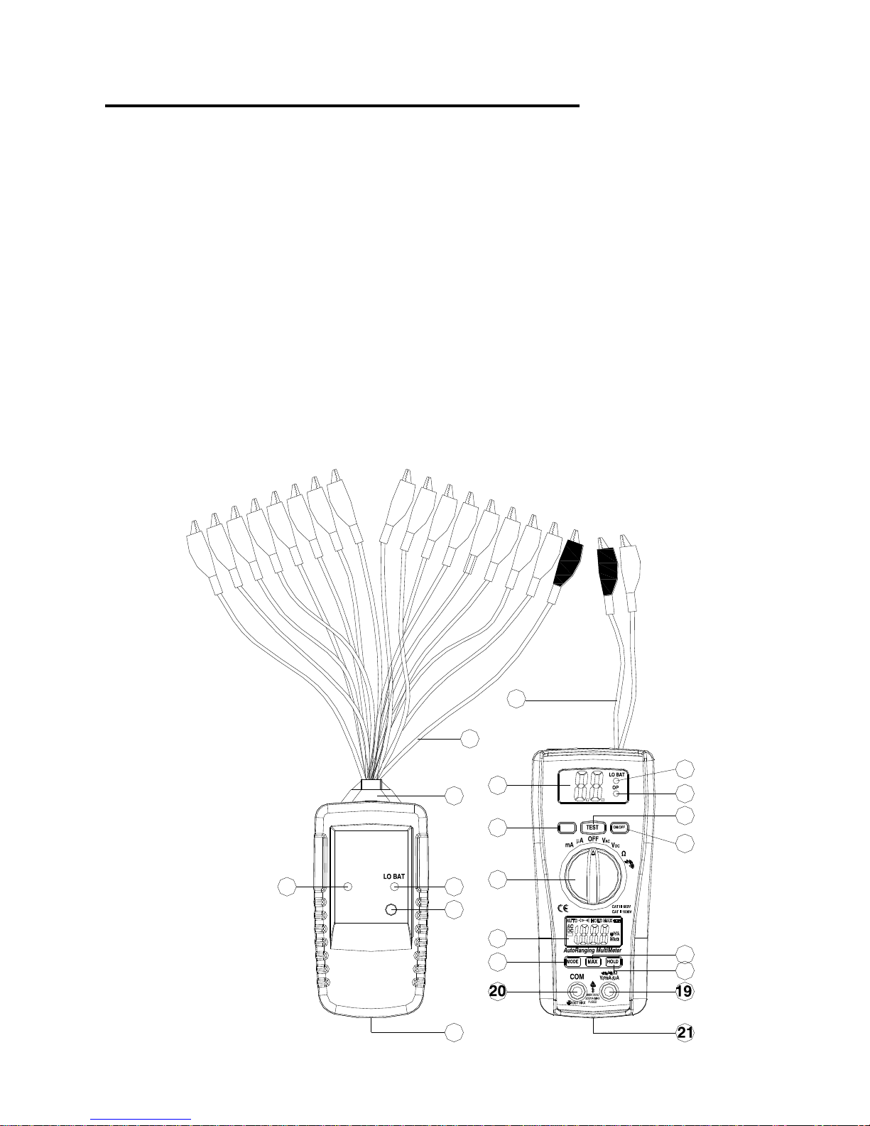
4.1 Transmitter&Receiver operation
1).At one end of the cable, Connect one of the transmitter
terminals marked “CH1 to CH16”to each core of the cable
under tester.Connect the “COM”reference lead (black
alligator) of the transmitter to a core which is the only known
one.
2).At the other end of the cable ,connect the “COM
terminal”(black alligator) of the receiver.
When the “input terminal”(red alligator) of the receiver is
successively touched on the cores of the cable under test,the
relevant number of the way is indicated on the display of the
receiver(1-16).
Operation example 1: Cable trace test
Operation example 2: Metal water pipe trace test
CAUTION: Though the units already build in the
protection circuit,however do not apply voltage that over
50V(AC or DCV)toany alligator clips of
transmitter&receiver. Otherwise the instruments may
defect permanently.
4.2 Beep alarm test : “TEST”button to down use receiver of
2Croc clips connect cable of two port if cable is put through
will have beep sound.otherwise cable isn’t put through or isn’t
same a cable.
CAUTION: Beep if less than 100Ω