Cembre PCM-2P/FC User manual

32
This manual is the property of
CEMBRE
:
any reproduction is forbidden without written permission.
CEMBRE
reserve the right to modify the specifications in this manual without prior notice.
cod. 6261264
www.cembre.com
CEMBRE Ltd.
Dunton Park
Kingsbury Road, Curdworth - Sutton Coldfield
West Midlands B76 9EB (UK)
Ph. +44 01675 470440 - Fax +44 01675 470220
www.cembre.co.uk
CEMBRE S.a.r.l.
22 Avenue Ferdinand de Lesseps
91420 Morangis (France)
Tél. +33 1 60 49 11 90 - Fax +33 1 60 49 29 10
CS 92014 - 91423 Morangis Cédex
www.cembre.fr
CEMBRE S.L.U.
Calle Verano 6 y 8 - P.I. Las Monjas
28850 Torrejón de Ardoz - Madrid (España)
Tel. +34 91 4852580
Fax +34 91 4852581
www.cembre.es
CEMBRE GmbH
Geschäftsbereich
Energie- und Bahntechnik
Heidemannstraße 166
80939 München (Deutschland)
Tel. +49 89 3580676
www.cembre.de
CEMBRE Inc.
Raritan Center Business Park
300 Columbus Circle - Suite F
Edison, New Jersey 08837 (USA)
Tel. +1 732 225-7415 - Fax +1 732 225-7414
www.cembreinc.com
CEMBRE S.p.A.
Via Serenissima, 9
25135 Brescia (Italia)
Tel. +39 030 36921
Fax +39 030 3365766
www.cembre.com
Geschäftsbereich
Industrie Handel
Boschstraße 7
71384 Weinstadt (Deutschland)
Tel. +49 7151 20536 - 60
www.cembre.de
1
MACHINE FOR PANDROL
MACHINE FOR PANDROL
“FASTCLIP” FASTENING
PCM-2P/FC
ENGLISH
ENGLISH OPERATION AND MAINTENANCE MANUAL
21M110E

2
14
2
1)Before using the machine read the instructions contained in this manual carefully.
SAVE THESE INSTRUCTIONS: this manual contains important safety and operating
instructions for the machine.
2)Alwaysuse PersonalProtectiveEquipmentsuchasis normallyrequiredbyyouremployer
and/or appropriate to your sector of operation.
3)Always wear hearing protection. Under normal operating conditions, this machine may
cause the operator to be exposed to a personal and daily noise level of over 85 db (A).
4)During operation keep your hands and all other persons outside the danger area.
- Always follow fuelling and refuelling practices and procedures normally required by
your employer and/or appropriate to your sector of operation.
- Machine operation is guaranteed only if used by well-trained users and expert on the
adjustments on the machine itself.
- Thedesign or configurationof the machine shall not be modified other than by CEMBRE.
- Cannot be used over switches and crossings.
- Not to be used near live d.c. conductor rail.
- Not to be used for any purpose other than for which machine is designed.
- Do not exceed walking pace when moving the machine along the rail.
- Wrong settings and operations may cause damage to the machine and to the rail
fastener .
- The machines will not function reliably if they are left“outside and uncovered”for long
periods of time exposed to the elements.
5)The machine fulfils the requirements of the Norm EN 13977.
WARNINGS
EN 13977
3 5
31
UK DECLARATION OF CONFORMITY
We: CEMBRE S.p.A. Via Serenissima, 9 – 25135 Brescia (Italy)
Declare under our sole responsibility that the product:
To which this declaration relates is in conformity with the following standard(s) or other normative document(s):
Following the provisions of the UK Legislation(s):
Brescia
Felice Albertazzi
CHIEF SALES & MARKETING OFFICER
Cembre S. .A.
p
EC DECLARATION OF CONFORMITY -
DECLARATION DE CONFORMITE - KONFORMITÄTSERKLÄRUNG -
DECLARACIÓN DE CONFORMIDAD - DICHIARAZIONE DI CONFORMITÁ
We Nous Wir Nos Noi: CEMBRE S.p.A. Via Serenissima, 9 – 25135 Brescia (Italy)
Declare under our sole responsibility that the product - Déclarons sous notre seule responsabilité que le produit
- Erklären in alleiniger Verantwortung daß das Produkt - Declaramos bajo nuestr responsabilidad que el producto
- Dichiariamo sotto nostra unica responsabilità che il prodotto:
To which this declaration relates is in conformity with the following standard(s) or other normative document(s)
- Auquel cette déclaration se réfère est conforme à la (aux) norme(s) ou autre(s) document(s) normatif(s) -
Auf das sich diese Erklärung bezieht mit der/den folgenden Norm(en) oder normativen Dokument(en) über-
einstimmt - Al que se refiere esta declaración, cumple la(s) norma(s) u otro(s) documento(s) normativo(s) -
Al quale si riferisce questa dichiarazione è conforme alla(e) norma(e) o altro(i) documento(i) normativo(i):
Following the provisions of Directive(s) - Conformément aux dispositions de(s) Directive(s) -
Gemäss den Bestimmungen der Richtlinie(n) - De acuerdo con las disposiciones de la(s) Directiva(s) -
Conformemente alle disposizioni della(e) direttiva(e):
Person authorised to compile the technical file - Personne autorisée à constituer le dossier technique -
Person die bevollmächtigt ist die technischen Unterlagen zusammenzustellen -
Persona facultada para elaborar el expediente técnico - Persona autorizzata a costituire il file tecnico:
Ennio Peroni Via Serenissima, 9 – 25135 Brescia (Italy)
Brescia
Felice Albertazzi
CHIEF SALES & MARKETING OFFICER
Cembre S. .A.
p
PCM-2P/FC
2006/42/EC 2014/30/EU
EN 13977 EN ISO 12100 EN ISO 3746 EN ISO 11202 EN ISO 5349-1 EN ISO 5349-2
PCM-2P/FC
S.I. 2008/1597 S.I. 2016/1091
EN 13977 EN ISO 12100 EN ISO 3746 EN ISO 11202 EN ISO 5349-1 EN ISO 5349-2
24-03-2021
24-03-2021

30
INDEX page
WARNINGS........................................................................................................................................................... 1
1. GENERAL CHARACTERISTICS.................................................................................................................... 3
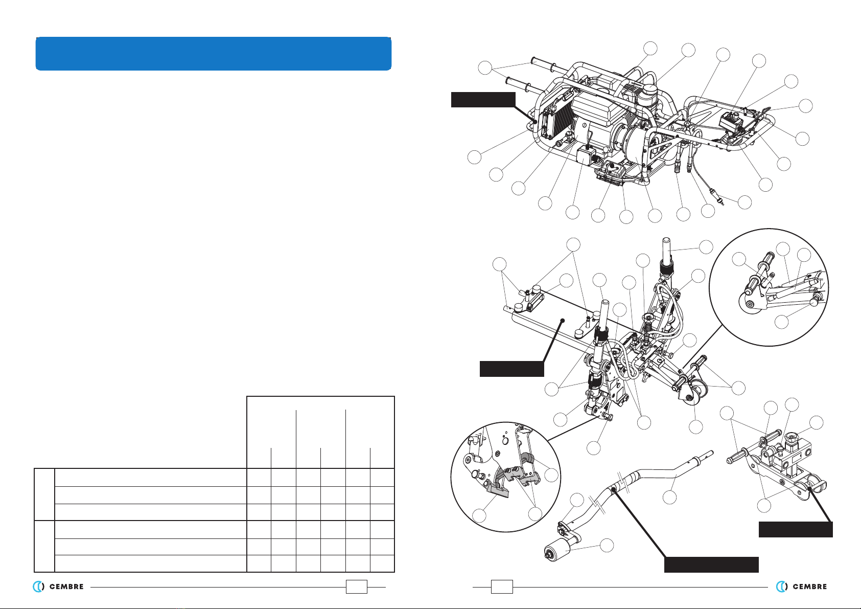
2. MACHINE DESCRIPTION............................................................................................................................... 4
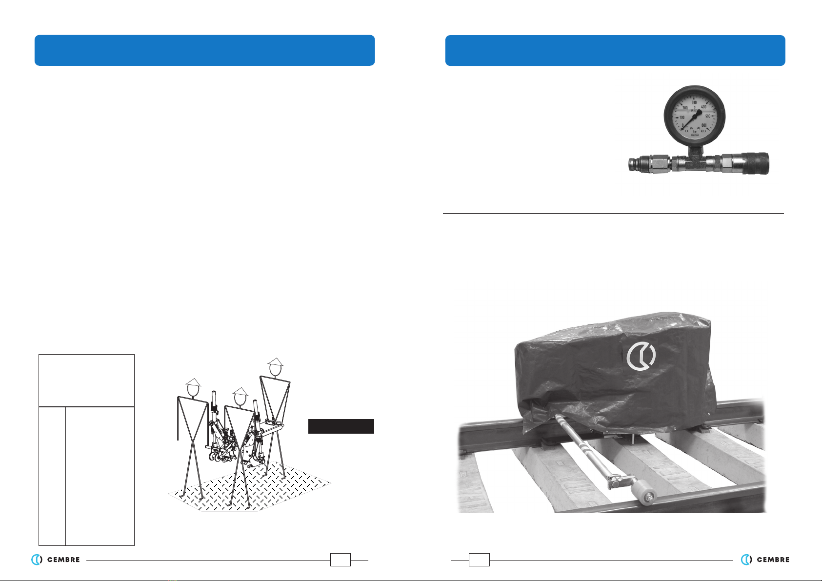
3. UNPACKING .................................................................................................................................................... 6
3.1 Transporting the units ............................................................................................................................... 6
4. INSTRUCTIONS FOR USE.............................................................................................................................. 7
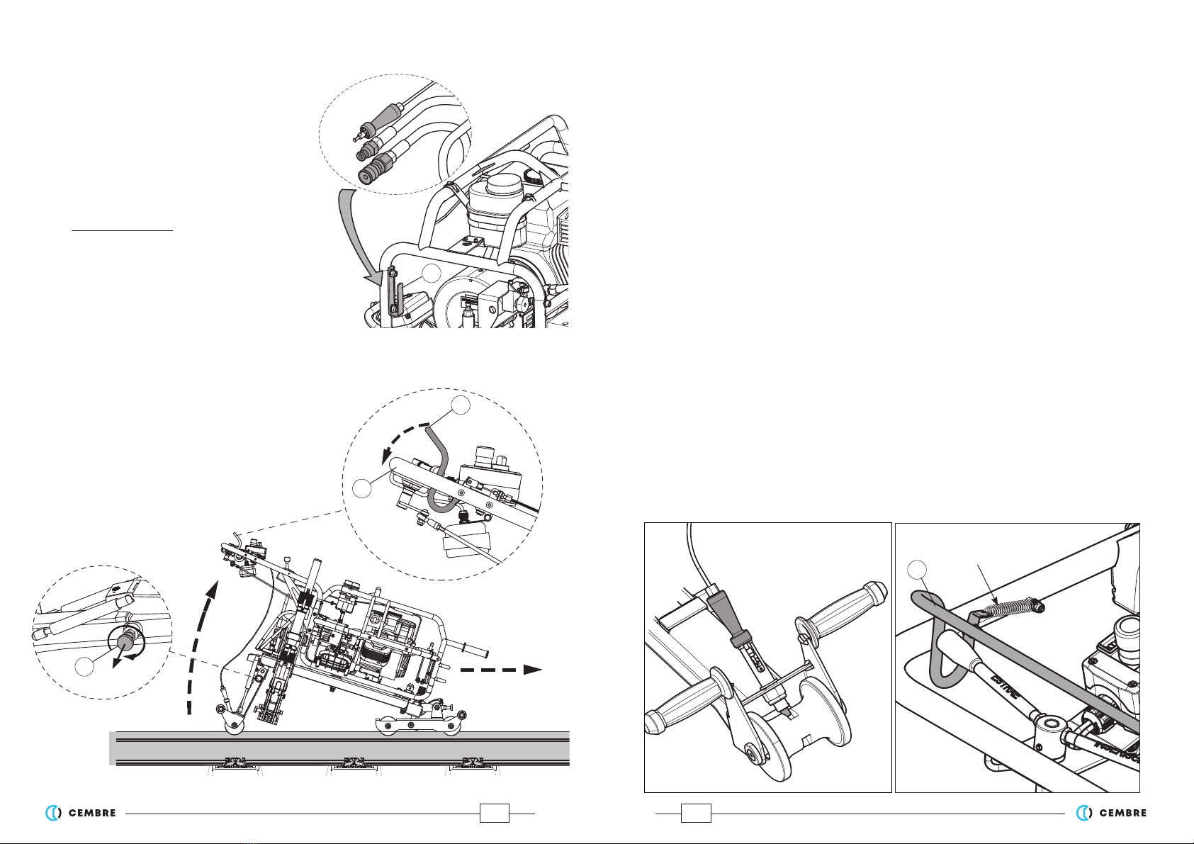
4.1 Assembly of the machine.......................................................................................................................... 7
4.1.1 Braking device.......................................................................................................................................... 8
4.1.2 Disassembly of the machine ................................................................................................................ 9
4.2 Moving the machine.................................................................................................................................. 9
4.3 Controls.......................................................................................................................................................11
4.4 Description of the Pandrol Fastclip ......................................................................................................12
4.5 Preliminary machine adjustments .......................................................................................................13
4.5.1 Centred positioning of contrast jaws ...............................................................................................13
4.5.2 Adjusting horizontal alignment........................................................................................................14
4.5.3 Stable rest of both the contrast jaws................................................................................................14
4.6 Operation ...................................................................................................................................................15
4.6.1 Simultaneous insertion of two Fastclip ...........................................................................................15
4.6.2 Simultaneous extraction of two Fastclip.........................................................................................16
5. ADJUSTING RAM STROKE ........................................................................................................................17
5.1 Adjusting ram stroke for the insertion operations............................................................................17
5.2 Adjusting ram stroke for the extraction operations .........................................................................18
5.1.1 Parking position of the Fastclips........................................................................................................18
5.1.2 Insulatort change position of the Fastclips.....................................................................................19
5.1.3 Complete extraction of the Fastclips from shoulders...................................................................19
6. STARTING THE ENGINE...............................................................................................................................20
7. MAINTENANCE.............................................................................................................................................22
7.1 Routine maintenance of the machine....................................................................................... 22
7.1.1 Maintenance of braking device.........................................................................................................22
7.1.2 Topping up the oil in the hydraulic pump .......................................................................................24
7.1.3 Changing worklight bulbs ..................................................................................................................24
7.1.4 Changing gas springs ..........................................................................................................................25
7.1.5 Maximum pressure valve ....................................................................................................................25
7.2 Routine maintenance of the engine.....................................................................................................25
7.3 Long periods of inactivity .......................................................................................................................25
8. ADDITIONAL ACCESSORIES AVAILABLE ON REQUEST........................................................................27
9. RETURN TO CEMBRE FOR OVERHAUL....................................................................................................28
3
– Application range: suitable for inserting and removing Pandrol Fast clips* on standard-
gauge rails (1435 mm).
– Developed force (single clamp): ..................................................................................................29.000 N
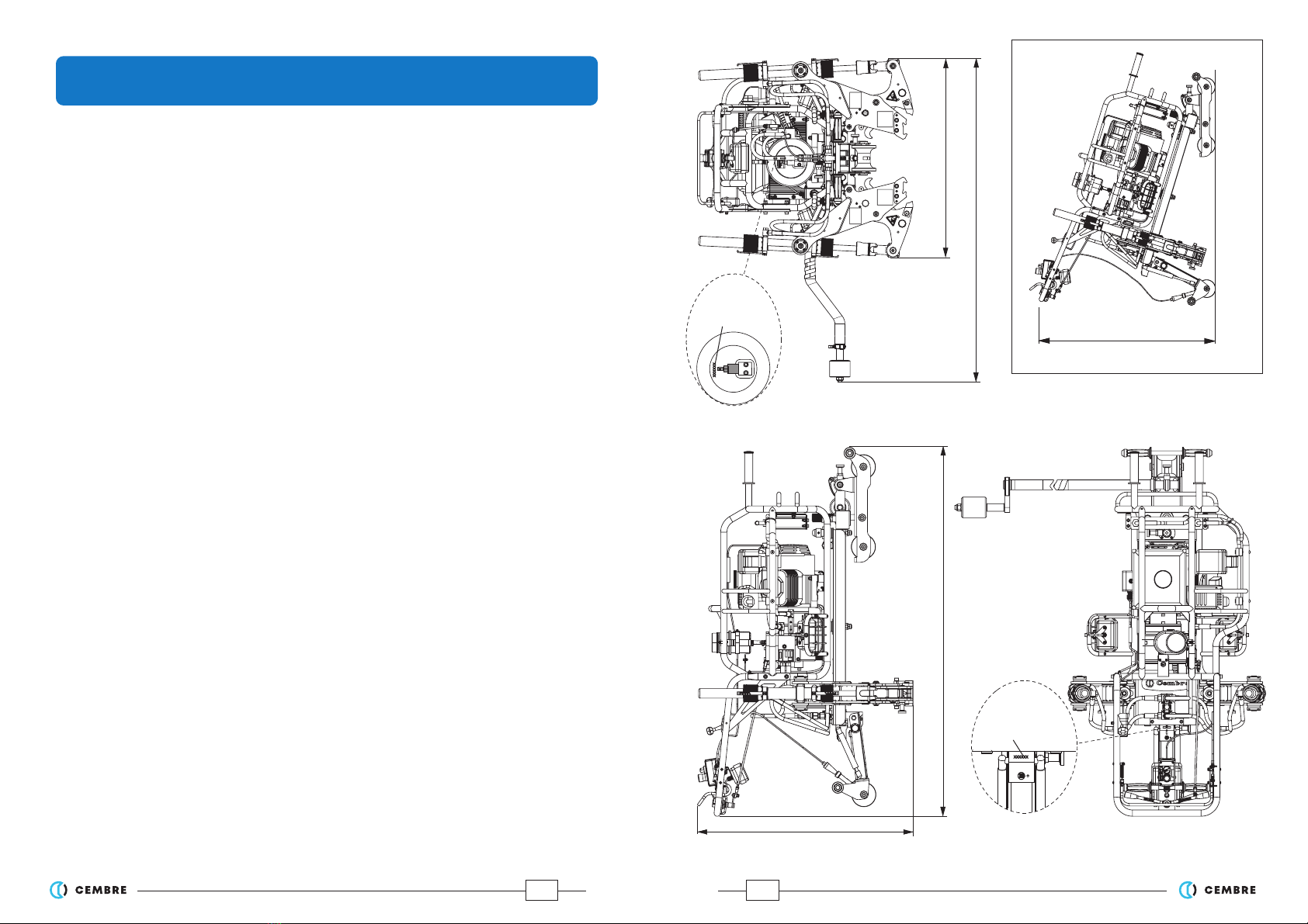
– Dimensions: ................................................................................................................. (see Fig. 25, page 29)
– Resistance between rail and wheel: ...............................................................................................≥1 MΩ
– Weight:
– complete machine: ..................................................................................................................................134 kg
– pump unit:
....................................................................................................................................................
55 kg
– clamp unit: .................................................................................................................................................... 65 kg
– carriage: ............................................................................................................................................................9 kg
–
3
rd wheel bar:...................................................................................................................................................5 kg
– Combustion engine:
– type:...............................................................................................4-stroke, overhead valves, one cylinder
– model:.....................................................................................................................
Honda GX200 UT2-SMCR OH
– displacement: ......................................................................................................................................... 196 cm3
– power:............................................................................................................................................ 4.3 kW 5.8 HP
– revs.:.........................................................................................................................................................3600 rpm
– fuel:
.................................................................................................................
unleaded regular grade petrol
– fuel consumption: .............................................................................................. 1.7 litres/hour (3600 rpm)
– fuel tank capacity: .................................................................................................................................3.1 litres
– recommended oil:.....................................................................................................SAE 10W-30 (0.6 litres)
– clutch: ......................................................................................... centrifugal with automatic intervention
– start:......................................................................................................by rope pull with automatic rewind
– Hydraulic pump:
– max. pressure:...........................................................................................................................................42 MPa
– oil supply: .................................................................................................................................5.6 litres/minute
– speed: ..................................................................................................................................................... 3600 rpm
– recommended oil:...................................................................................... ENI ARNICA 32 or equivalents
– Acoustic noise (Directive 2006/42/EC, annexe 1, point 1.7.4.2 letter u)
– The continuous equivalent weighted level (A) of noise pressure
at the working place LpA is equal to ................................................85,2 dB (A), uncertainty KpA ± 4 dB
– The maximum value of instantaneous weighted noise pressure C
at the working place LpCPeak is.....................................................................................................< 130 dB (C)
– The level of noise force produced
by the machine LWA is equal to........................................................ 95,1 dB (A), uncertainty KWA ± 4 dB
–Risks due to vibration (Directive 2006/42/EC, annexe 1, point 2.2.1.1)
Tests carried out in compliance with the indications contained in ISO 5439 Standard, and under
operating conditions much more severe than those normally found, certify that the weighted
root mean square in frequency of the acceleration the upper limbs are exposed to for each
biodynamic reference axis is ahv = 2,44 m/s2uncertainty K ± 0,8 m/s2.
1.
GENERAL CHARACTERISTICS
(*) "Pandrol Fast clip" is a Pandrol Ltd trademark.

4
01 – TRANSPORT HANDLES
02 – MACHINE LIFTING POINT IN NEUTRAL POSITION
03 – HYDRAULIC PUMP OIL TANK
04 – ACCELERATOR
05 – WORKLIGHT ON/OFF SWITCH
06 – STOP/EMERGENCY BUTTON
07 – CLAMP CONTROL LEVER
08 – HANDLEBAR
09 – QUICK RELEASE MALE AUTOMATIC HYDRAULIC COUPLER
10 – QUICK RELEASE FEMALE AUTOMATIC HYDRAULIC COUPLER
11 – HYDRAULIC PUMP
12 – PUMP UNIT FASTENING/RELEASE KNOB
13 – WORKLIGHT
14 – ELECTRICAL TERMINAL BOX
15 – ENGINE
16 – PUMP UNIT FASTENING/RELEASE KNOB
17 – OIL COOLING RADIATOR
18 – FRAME
19 – CLAMP UNIT LOCATING PINS
20 – PUMP UNIT LOCATING PINS
21 – TRANSPORT HANDLES
22 – HYDRAULIC RAM FOR MOVING THE LEFT CLAMP
23 – KNOB FOR REGULATING THE POSITION OF THE LEFT CLAMP
24 – QUICK RELEASE MALE AUTOMATIC HYDRAULIC COUPLER
25 – QUICK RELEASE FEMALE AUTOMATIC HYDRAULIC COUPLER
26 – HYDRAULIC RAM FOR MOVING THE RIGHT CLAMP
27 – GAS SPRING LEFT SIDE
28 – GAS SPRING RIGHT SIDE
29 – WHEEL LOCK/RELEASE KNOB
30 – KNOB FOR REGULATING THE POSITION OF THE RIGHT CLAMP
32 – BRAKE RELEASE DEVICE LOCK
33 – TRANSPORT HANDLE
34 – WHEEL
35 – FLEXIBLE HOSES
36 – EXTRACTION HOOK FASTENING/RELEASE KNOB
37 – RAM OVERRUN SPACER
38 – RING NUT FOR REGULATING RAM END OF STROKE
39 – BAR
40 – WHEEL ADJUSTMENT LEVER
41 – SUPPORT WHEEL
42 – INSERTING TOOTH
43 – CONTRAST JAWS
44 – EXTRACTION HOOK
45 – TRANSPORT HANDLES
46 – CONNECTING ROD FASTENING/RELEASE KNOB
47 – HORIZONTAL ALIGNMENT ADJUST KNOB
48 – CLAMP UNIT FASTENING/RELEASE KNOB
49 – FRONT CARRIAGE WHEELS
50 – BRAKE RELEASE HANDLE
51 – BRAKE RELEASE DEVICE
2. MACHINE DESCRIPTION (Ref. to Fig. 1)
29
xxxxxx
xxxxxx
FIG. 25
DIMENSIONS (mm)
830
1000 max.
Pump unit
serial
number
2000
1470
Clamp unit
serial
number
875

28
RING NUT SETTINGS
Ring
nut
upper
ADJUSTMENTS:
We suggest recording all adjustable Ring nut settings in
the table alongside to facilitate quick ‘resetting’ in future.
From «parking position» to «installation position».
From «insulator change position» to «installation position».
Complete insertion of the Fastclip.
From «installation position» to «parking position».
From «installation position» to «insulator change position».
Complete extraction of the Fastclip.
INSERTIONEXTRACTION
RAIL: RAIL: RAIL:
Ring
nut
lower
Ring
nut
upper
Ring
nut
lower
Ring
nut
upper
Ring
nut
lower
In the case of a breakdown contact our Area Agent who will advise you on the problem and give
you the necessary instructions on how to dispatch the machine to our nearest service Centre; if
possible, attach a copy of the Test Certificate supplied by CEMBRE together with the machine
or fill in and attach the form available in the“ASSISTANCE” section of the CEMBRE website.
9. RETURN TO
CEMBRE
FOR OVERHAUL
5
26
21
20
19
22
23
25
24
29
33
34
35
37
38
36
27 28
41
39
40
3rd WHEEL BAR
PUMP UNIT
CLAMP UNIT
CARRIAGE
30
49
45
48
47
46
01
02 03 04 05
06
07
09
10
11
12
13
14
15
16
17
18 08
13
FIG. 1 – MACHINE DESCRIPTION
50
51
32
36
PUMP UNIT
43
44
42

6
.
To reduce overall dimensions and weight during transport, the machine is supplied disassem-
bled in sturdy wooden crates.
The four component units are easily reassembled (see Fig. 1):
– Pump unit: combustion engine/hydraulic pump for clamp operation.
– Clamp unit: for inserting and extracting Fastclips.
– Carriage: for supporting and moving the machine along the track.
– 3rd wheel bar: for stability and vertical positioning.
The machine is supplied complete with:
– 1pc spark plug key.
– 1litre hydraulic pump oil (do not use in engine).
– 1pc 12V - 21W spare bulb.
3.1) Transporting the units
The four units are well balanced for easy transportation in accordance with the table and dia-
grams in Fig. 2. For uniform weight distribution and to transport the pump and clamp units,
always use the transportation handles provided.
3. UNPACKING THE MACHINE
AB
C
CLAMP UNIT
A 20
B 20
C 25
D 9
E 5
F 15,5
G 15,5
H 24
Distributed Load
per Person
(kg)
27
8. OPTIONAL ACCESSORIES
MPC6 PRESSURE GAUGE code 2595209
To check maximum pressure valve setting.
PROTECTIVE COVER FOR PANDROL CLIP MACHINE:
TARPCOVER 019-PCM code 2593275
(material: Polyethylene HDPE
UV stabilised, + 70 °C to - 40 °C)

26
General cleaning with a clean
cloth, paying attention to remove
settled dirt
Store the machine in dry place
protecting it from shocks
and dust
Visual & manual checks of
(tighten if necessary)
Complete tightening
Visual check of integrity
Replacement
Visual & manual checks
(tighten if necessary)
Complete tightening
Visual & manual checks of integrity
Replacement
Visual & manual checks of
integrity
Replacement
Check reservoir level
(Top up if necessary)
Replacement
Replacement
Visual & manual checks of integrity
PERIODIC OVERHAUL
Performed at the prescribed intervals or at the number of indicated
working hours or at the occurrence of indicated extraordinary events
At every use
Presence
of evident
signs of wear
In case of
breakage
Long periods
of inactivity
ITEM ACTION
Complete machine
Bolts and nuts
Flexible hose
Hydraulic couplers
Rubber dampers
of the machine
Inserting teeth (42)
Extracting hooks (44)
Contrast jaws (43)
Hydraulic oil
Light bulbs and fuse
Gas springs
50 hours
Braking device & wheels
Ref. to § 7.1.1
7
D
G
F
E
3rd WHEEL BAR
2–
1–
4.1) Assembly of the machine
Select the rail to be worked on and the direction of operation, then assemble the machine as
follows, referring to fig. 4:
With knob (29) engaged and wheel (34) blocked, raise the clamp unit by means of
the handles (33) and rest this on the selected rail, positioning it in line with a
sleeper for stability.
Rest the support carriage on the track and then pull and turn the fastening/release
knob (48). Lift the clamp unit by means of the handle (21) and locate (19) pins fully
into their carriage housings as far as the stop.
Release the knob (48) to lock the clamp unit.
FIG. 2 – TRANSPORTING THE UNITS
PUMP UNIT
CARRIAGE
4. INSTRUCTIONS FOR USE
H

8
Pull and turn the knob (46), insert the 3rd wheel bar in the carriage housing as far
as the stop, aligning the hole in the end of the rod with the pin knob.
Release the knob (46) so the wheel (41) can act as a support on the opposite rail so
the assembly is stable and able to slide along the rail; the rod can be fitted to the
carriage from either side for convenience in selecting the direction of work.
Pull and turn the knobs (12 and 16) at the base of the pump unit.
Lift the pump unit by means of the handles (01) and handlebar (08).
Rest the pump unit on the clamp unit and align the pins (20) with the relevant locating
holes on the under side of the pump unit. Release the knobs (12 and 16) for locking.
Restore the oil delivery/return hydraulic circuit, connecting the flexible hoses by
means of the quick couplings (09 and 10) to the respective connectors (25 and 24)
on the clamp unit.
Connect the brake release device (51) (ref. to § 4.1.1)
3–
4–
5–
6–
4.1.1) Braking device (Ref. to Fig. 3a, 3b, 3c, 5)
To run the machine along the rail, it is necessary to connect
the brake release device (51), proceed as follows:
– Introduce end part (A) into slot seat (B) located above
the rear wheel of the clamp unit (
Ref. to Fig. 3a)
.
– Pull the handle (C) upwards, release it in position than
push until is locked (
Ref. to Fig. 3b and c)
.
– Pressthehandle(45)toverifythecorrectengagementand
disengagement of release pin (P) from the wheel (
Ref. to
Fig. 5 and 3c)
.
During the disassembly of the machine, before removal
of the pump unit, the brake release device must be disas-
sembled as follows:
– Pull the handle (C) and disconnect the end part (A)
from slot seat (B).
A
B
C
FIG. 3a
FIG. 3b FIG. 3c
51
P
25
FIG. 24
7.2) Routine maintenance of the engine
Checks and periodical assistance are indispensable to ensure smooth engine operation.
Refer to the "HONDA owner’s manual" supplied with the machine, for the following operations:
– Oil change
– Air filter assistance (see double-element type)
– Cleaning sediment from sump
– Spark plug cleaning; recommended plugs BPR6ES (NGK) or W20EPR-U (DENSE)
– Minimum carburettor setting
7.3) Long periods of inactivity
– Store the machine in a dry environment, and adequately protect it against accidental
damage and contamination (see § 8).
– For information on the combustion engine, refer to the "HONDA owner’s manual"
.
7.1.4) Changing the gas springs (Ref. to Fig. 23)
Replace the gas springs when required
as follows:
– Using a flat-blade screwdriver, lift the retention
collar at the end of the spring, pulling with force
at the same time to release the spring from its
locating pins.
– Fit the new spring on the same pins and press
withforceuntilthisisproperlyfittedintheoriginal
position.
Note: the two springs differ from one another.
7.1.5) Maximum pressure valve (Ref. to Fig. 24)
The hydraulic pump features a maximum pressure
valve, factory set and sealed at 42 Mpa.
NEVER CHANGE THE MAXIMUM PRES-
SURE VALVE SETTING AS THIS MAY CAUSE SERI-
OUS DAMAGE TO THE MACHINE.
To check correct valve setting, a special pressure
testing gauge is available (see § 8).
FIG. 23
Maximum
pressure
valve
screwdriver
gas spring

24
14
FIG. 22
FIG. 19
FIG. 20
FIG. 21
7.1.2) Topping up the oil in the hydraulic pump (Ref. to Fig. 19)
Periodically check the level of the oil in the hydraulic
pump. The oil should always be visible inside the
tank (03). If the level is low, top up with the specific
oil recommended:
– Unscrew the cap and add sufficient oil to fill the
tank; do not exceed the oil level.
– After topping up, tightly screw the cap back on.
Always use clean recommended oil, see § 1.
Do not use old or recycled oil.
Do not use hydraulic brake fluid.
7.1.3) Changing worklight bulbs
– Loosen the locking nut (Ref. to Fig. 20).
– Turn worklight upwards and remove the two
screws in the lens (Ref. to Fig. 21) using a screw-
driver.
–
Remove the faulty bulb and replace with another
having the same specifications: 12V - 21W
– Replace lens and tighten the two screws.
– Reset worklight to original position and tighten
the nut.
The light bulb power circuit is protected by a
fuse against overcurrents and short-circuits.
In case of a fault:
– Remove the 4 screws from the lid of the termi-
nal box (14) using a screwdriver.
– Pull out fuse carrier and open it (Ref. to Fig. 22).
– Replace faulty fuse with a new one with the
same specifications: 6,3A - 250V.
– Push fuse carrier back, replace lid and tighten
4 screws.
fuse-carrier
light bulb
12V - 21W
locking
nut
03
9
DIRECTION OF MOVEMENT
3
5
4
1
2
34
48
21
19
46
41
16
12
20
20
09
10
24
25
08
01
33
FIG. 4 – SEQUENCE OF ASSEMBLY
SLEEPER
RAILS
29
51
6

10
4.2) Moving the machine (Ref. to Fig. 4b)
To move the machine along the track, the rear part must be raised to prevent the clamps knock-
ing against the Fastclip.
1 - Pull and turn knob (29). The wheel arm will be freed.
2 -Slightly raise the machine by means of
handlebar (08); lifting will be made easier by
the two gas springs, then release the knob (29)
to lock the machine fully up.
3- Press brake release handle (50) against the
handlebar (08).
4- Push the machine along the rail.
FIG. 4b – MOVING THE MACHINE
08
2
3
50
4
29
1
S
4.1.2) Disassembly of the machine (Ref. to Fig. 4 and 4a)
To disassemble the machine:
– First lower the rear part and lock with pin
(29), block wheel (34) then reverse the pro-
cess described in § 4.1.
– Before disconnecting the pump unit, make
sure
to have disconnected the hydraulic
circuit and
the braking device; locate the
hoses in support
(S) got on the frame of the pump unit.
If necessary, with the machine fully assembled and
the motor switched off, the clamps can always be
opened or closed manually.
NOTE: Under normal conditions, the time taken to
remove the machine from the rail is approximately
60 seconds.
FIG. 4a – SUPPORT
23
Before every use:
– Check wheel for resistance, wheel should not be free rotating.
– Ensure wheel is clean, removing any dirt or mud.
– Check for signs of damage.
Every 6 months:
– Check for excessive braking on wheel. Wheel should roll along track when pushed,
wheel will slide if excessive braking occurs.
Clamp unit wheel
Before every use:
– Check cable, linkages, springs and wheel for signs of damage.
– Check linkages are free moving.
– Ensure brake cable moves without resistance.
– With brake released, check that wheel rotates freely.
– Check that when handlebar lever is in the raised position, the brake is engaged.
– Ensure that wheel is clean of dirt and mud.
– Check that, before assembly, the wheel does not rotate one full turn in either direction.
– Ensure coupling is free of dirt and mud.
Every 6 months
– Check wheel pockets for excessive wear. If braking effectiveness is compromised,
replace wheel.
– Check extension spring (see figure) on brake release handle (50) are undamaged.
– Check for wear on pivots.
– Ensure fasteners are secure.
– Check for wear on coupling, parts should mate securely.
– Clean all moving parts and lubricate as required.
50
extension
spring

22
7. MAINTENANCE
Before servicing or removing any parts of the machine, stop the engine and allow it to
cool. Always remove the spark plug cap from the spark plug when servicing the engine
to prevent accidental starting.
All electrical and mechanical maintenance shall only be carried out by authorised persons
in accordance with a safe system of work and CEMBRE instructions.
7.1) Routine maintenance of the machine
At the end of each day, clean the machine carefully using a clean cloth, being careful to remove
all dirt, especially near the moving parts such as the clamp teeth, piston rods and wheels. Do
not rest the machine or units directly on dusty or muddy ground.
Regularly perform the following operations or inspections:
– Tighten all bolts.
– Check the integrity of the rubber dampers which reduce vibration caused by the en-
gine-pump.
–If necessary, replace the insertion teeth (42), the hooks (44) and jaws (43) as these
could become worn or damaged by long or improper use.
7.1.1) Maintenance of braking device (only for versions of machine with braked wheels)
The braking system is robust and will require very little maintenance, however the following
routine checks should be performed.
Dust, sand and dirt are a danger for any mechanical device. Avoid putting the machine on
muddy ground. After every use, the machine must be wiped with a clean cloth, taking care to
remove any residue, especially around moving parts.
Rear Carriage wheel (A):
(A)
11
4.3) Controls (Ref. to Fig. 5)
After gripping the handlebar (08), the operator can easily access all the unit controls and,
more specifically:
– Accelerator control lever (04): changes engine rpm.
– Worklight ON/OFF switch (05): in case of night work or bad lighting, the clamping
area can be illuminated by these side mounted lamps.
– Stop/emergency button (06) in a very visible position and easy to operate to stop the
unit normally and in case of an emergency.
NOTE: when this button is pressed it remains in OFF position. To start the engine, the button
should be turned clockwise so that it lifts automatically into the ON position.
The engine will not start unless the red button (06) is lifted.
– Clamp control lever (07) with swinging movement, for operating the clamps:
- right side for inserting rail clips, "INSERT" position
- left side for extracting rail clips, "EXTRACT" position
–
Brake release lever (50): for safety reasons, the machine is equipped with an auto-
matic braking device. This device is always engaged within the rear wheel.
By pressing handle (50), the brake is released enabling movement of the machine along
the rail.
FIG. 5 – CONTROLS
EXTRACT
INSERT
05
07
06
04
50
08

12
Fastclip
Toe insulator
Shoulder
Side post insulator
4.4) Description of the "Pandrol Fastclip" (Ref. to Fig. 6)
The “FASTCLIPS”have three positions:
PARKING POSITION
All components are captive.
INSTALLED POSITION:
The Fastclip holds the rail.
INSULATOR CHANGE POSITION :
The Fastclip is withdrawn to the rear detent so that the
side post insulator can be removed.
FIG. 6 – FASTCLIP
21
TROUBLESHOOTING
When the starting cable is pulled, the engine fails to start:
Is the Stop/Emergency button (06) released? (see § 4.3).
Is there enough oil in the combustion engine?
– The engine features an oil alert system to prevent damage caused by too little
oil. Before the level drops below safe limits, the alarm system automatically
stops the engine.
Refer to the "HONDA owner’s manual" for the type of recommended oil and topping up.
THE HYDRAULIC OIL SUPPLIED WITH THE MACHINE IS INTENDED ONLY FOR
USE IN THE HYDRAULIC PUMP AND IS MUST NOT BE USED IN THE ENGINE.
Is the fuel stopcock open?
Is there fuel in the tank?
Is fuel reaching the carburettor?
– To check, loosen the carburettor drainage screw with fuel cock open and refer to the
"HONDA owner’s manual" .
Is the spark plug producing a spark?
– Remove the plug cap, clean around of the plug and remove the plug using the span-
ner provided.
– Fit the plug back in the cap.
– Move button (06) to ON.
– After earthing the side electrode, pull the starting cable and check to see whether the
plug produces a spark.
If the engine still fails to start, contact
CEMBRE
(see § 9).

20
FIG. 18d
– Move the stop button (06) (see § 4.3) to "ON"
position (see Fig. 18a).
The engine will not start unless the
red button (06) is lifted.
– Move the fuel cock to "ON" position
(see Fig. 18b).
– Move the air lever to "CLOSE" position
(see Fig. 18b).
Do not use the air lever if the engine is hot and
the air temperature is high enough.
– Move the accelerator control lever (04) to mid
stroke (see Fig. 18c).
– Start the engine by pulling the starting cable un-
til a certain resistance is felt and then pull with
force (see Fig. 18d).
IMPORTANT: Do not allow the cable knob to
return forcefully and knock against the engine.
Return this slowly to its original position. This
will prevent damage to the starting device.
– As the engine heats up, gradually move the air
lever to "OPEN" position (see Fig. 18b).
– Move the accelerator control lever (04) fully for-
ward to achieve the correct rpm (see Fig. 18c).
–To stop the engine in emergency condition,
press button (06).
–To stop the engine in normal conditions:
move the accelerator control lever (04) fully back.
Press the button (06).
Move the fuel cock to "OFF".
6. STARTING THE ENGINE
Air lever
CLOSE
OPEN
Fuel cock
OFF
ON
Starting
cable knob
FIG. 18b
06
FIG. 18a
04
FIG. 18c
13
4.5) Preliminary machine adjustments (to be made with the engine switched OFF)
The machine is extremely versatile and adaptable to the many operating situations to be found
along a railway line (different types of rails, UIC60 etc. with different flange heights and widths,
different types of Fastclips and anchoring supports); for this reason, before using, some initial
adjustment will be required to define the correct machine setup during work.
It is most important that the following conditions be met for subsequent Fastclip insertion and
extraction operations:
– Contrast jaws of both clamps centred on the shoulders of the Fastclip supports
and resting perfectly on their top (§ 4.5.1 and § 4.5.3).
– Movement of the machine parallel with the rail (§ 4.5.2).
– Move the machine up to a pair of
Fastclips.
– Lower the machine completely to
determine the position of the con-
trast jaws (43).
– If necessary, turn the knobs (23
and 30) clockwise to move the
clamps away from the rail or anti
clockwise to move them closer to
the rail (see Fig. 7).
– Continue adjusting until the moving
jaws centre on the top of the sup-
port shoulders.
– Lower the machine to make sure
it is correctly supported as shown
in Fig. 8.
30 23
resting resting
OK
AB
AB B A
FIG. 7
FIG. 8
43
43
Machine adjustment is essential to ensure correct operation
4.5.1) Centred positioning of contrast jaws (Ref. to Fig. 7)
The two clamps are independent of each other, so it will be necessary to adjust knobs (23 and
30) to set the positions of both the contrast jaws (43).

14
4.5.3) Stable rest of both the contrast jaws (Ref. to fig. 10)
Both contrast jaws (43) must be supported in the same way on the top of the support
shoulders (see Fig. 8). If this is not the case, after making the adjustments described in
§ 4.5.1 and § 4.5.2 proceed to adjust the machine vertically by means of the support wheel (41):
– Fully lower the machine so it is resting on the support shoulders.
– Loosen handle (40).
– Lower or raise the rod (39) to change the vertical angle of the machine and achieve correct
alignment.
– After making adjustments, fully retighten handle (40).
FIG. 10
41
39
40
4.5.2) Adjusting the height of the front of the machine
– Fully lower the machine so it is resting on the
support shoulders.
– Line up the side of the machine so that the
clamp unit is parallel with the upper surface of
the railhead. If this is not the case, adjust knob
(47) on the carriage (Ref. to Fig. 9).
To lift the machine turn knob (47) anti-clocwise.
To lower the machine turn it clockwise.
The measuring scale will facilitate adjustment
by precisely defining the correct position of the
machine.
Note: It may be easier to use the knob (47) with the clamp unit partially disconnected from the
carriage by the knob (48)
FIG. 9
After making the adjustments described in § 4.5.1
proceed to adjust the machine horizontally as follows:
0
1
2
3
4
5
48
47
19
If this is not the case, turn the lower ring nut anticlockwise to increase the ram stroke
or clockwise to reduce it, then try another extraction; several attempts may be neces sary
to achieve exact Fastclip position. Use the graduated scale for fine and precise
adjustment.
– Once exact adjustment has been made on a ram, position the ring nut of the other ram
on the same graduated scale value.
5.2.2) "Insulator change position" of the Fastclips:
Follow the instructions at § 5.2.1 being careful to regulate the lower ring nut so as to increase
ram stroke, thereby favouring greater Fastclip return movement.
5.2.3) "Complete extraction" of the Fastclips from shoulders;
For all the operating stages described so far, the spacers (37) must be in the position shown
in Fig. 17a, for total extraction of the Fastclips only. Ram overrun will be necessary. This can be
obtained in the following way:
– Move the clamps fully forward by pulling the control lever (07) to the right to “INSERT”
position.
– Lift the spacers (37) (see Fig. 17a), turn them by 90° (see Fig. 17b) and move them
back down (see Fig. 17c) so the long slot fits into the stop; this will ensure complete
exit of the Fastclip.
We suggest recording all adjustable Ring nut settings in the table on page 29.
FIG. 17a
stop
37
FIG. 17b FIG. 17c
6 - 12 mm
PARKING
POSITION
FIG. 16
Toe insulator
Side post insulator
Rail

18
5.2) Adjusting ram stroke for the extraction operations
During extraction, the upper ring nut establishes ram stroke during movement of the clamp
towards the rail; to adjust this, proceed as follows:
–Fully turn the upper ring nut clockwise until the reference line is in proximity to POS. 4.
–
Once exact adjustment has been made on a ram, position the ring nut of the other ram
on the same graduated scale value.
The lower ring nut establishes the ram stroke during extraction. To adjust, proceed as follows:
– Turn the lower ring nut of a ram until the reference line is in intermediate position of
the graduated scale, POS. 2.
5.2.1) "Parking position" of the Fastclips:
– Perform a removal operation (see § 4.6.2) and check the position of the Fastclip.
When in “parking position” the Fastclip hood must normally be 6 - 12 mm from the edge
of the side post insulator (see Fig. 16), unless otherwise indicated.
123
FIG. 15
44
36
UPPER
RING NUT
LOWER
RING NUT
graduated scale:
0 = max. stroke
4 = min. stroke
FIG. 14
graduated scale:
0 = max. stroke
4 = min. stroke
clockwise
anticlockwise
clockwise
anticlockwise
reference line
reference line
– Make sure the clamps are open by pulling
the clamp control lever (07) to the left in
“EXTRACT” position.
– Fully lower the machine at the Fastclip points.
– Pull and turn knob (36) to release the ex-
traction hook (44) which will position hori-
zontally (see Fig. 15).
– Move the extraction hook (44) fully forward
by pulling the control lever (07) to the right
to “INSERT” position.
– Check the position of the hook (44) at the
end of stroke; if necessary, adjust the ring
nut by turning anticlockwise to increase the
stroke and position the fastener just after
the Fastclip hood (see Fig. 12a).
15
4.6) Operation
Before use, always check:
– Integrity of the machine.
– The correct coupling of the units making up the machine.
– Correct connection of the quick couplings and the braking device.
– Correct level of oil in pump.
– For any oil leaks in the hydraulic circuit (radiator, hoses, pump).
– Flexible hoses are in good condition and show no signs of wear or crushing.
– Protection devices in the clamp areas are firm and show no signs of damage.
– That the engine fuel tank cap is tight. Petrol is highly inflammable and can explode.
– Start the engine (see § 6).
– With knob (29) released, push the machine to the rail clips points on which operations
are to be performed (see § 4.2).
4.6.1) SIMULTANEOUS INSERTION OF 2 FASTCLIPS
Make sure the locking knob (29) of the wheel is released (see § 4.2).
An "Insertion operation" means (see § 4.4):
1 - Moving from “parking position” to “installation position”.
2 - Moving from “insulator change position” to “installation position”.
3 - In exceptional cases, the complete insertion of the Fastclip.
– Push the machine to the Fastclips on which operations are to be performed (see § 4.2).
IMPORTANT: when performing the first insertion operation, the correct stroke of the
rams will have to be established so the Fastclips are positioned precisely (see § 5.1).
–
Make sure the clamps are open by pulling the clamp control lever (07) to the left “EXTRACT”
position.
– Fully lower the machine and position the jaws (43) so these rest on the top of the
support shoulders (see Fig. 11).
– Pull the control lever (07) to the right “INSERT” position and keep this pressed until
clamp movement stops: gradual tooth
(42) feed will be obtained with conse-
quent insertion of both the Fastclips see
Fig. 11.
Once insertion is completed, pull the
control lever to “REMOVE” position so the
clamps move back.
Lift the machine, move to the next Fastclips
and repeat the above operations.
NOTE: Because the two clamps are indepen-
dent, their movement may be different, with
different reaction times.
Movement of one of the clamps is schematically shown in the illu-
stration; the other will have an identical and opposite movement.
42
43

16
4.6.2) SIMULTANEOUS EXTRACTION OF 2 FASTCLIPS
Make sure the the locking knob (29) of the wheel is released (see § 4.2).
An "Extraction operation" means (see § 4.4):
1 - Moving from “installation position” to “parking position”.
2 - Moving from “installation position” to “insulator change position”.
3 - In exceptional cases, the complete extraction of the Fastclip.
– Push the machine to the Fastclips on which operations are to be performed (see § 4.2).
IMPORTANT: when performing the first extraction operation, the correct stroke of the
rams will have to be established so the Fastclips are positioned precisely (see § 5.2).
– Make sure the clamps are open by pulling the clamp control lever (07) to the left “EXTRACT”
position.
– Pull and turn knob (36) to release the extraction hook (44) which will position horizon-
tally (see Fig. 15).
– Fully lower the machine and position the jaws (43) so these rest on the top of the
support shoulders (see Fig. 12a).
–
Move the extraction hook (44) fully forward by pulling the control lever (07) to the right
“INSERT” position (see fig. 12a).
– After positioning on the Fastclip, pull the control lever (07) to the left to “EXTRACT”
position and keep it pressed until clamp movement stops: the hooks (44) will gra-
dually
move back, with consequent removal of both the Fastclips (see Fig. 12b).
After removal, pull the control lever (07) to the right to “INSERT” position until the ma-
chine is released.
– Lift the machine, move to the next Fastclips and repeat the above operations.
–
Having completed the operation, return the hooks (44) to the vertical position and block
these with knobs (36).
Movement of one of the clamps is schematically shown in the illustrations; the other will have an identical and opposite movement.
FIG. 12a FIG. 12b
44
43 44
NOTE: Because the two clamps are independent, their movement may be different, with
different reaction times.
17
5.1) Adjusting ram stroke for the insertion operations
The upper ring nut establishes the stroke of the ram during forward movement of the clamp
towards the rail during Fastclip installation; to adjust this, proceed as follows:
– Turn the upper ring nut of a ram until the reference line is in the intermediate position
of the graduated scale, POS. 2 (see Fig. 14).
– Perform an insertion operation (see § 4.6.1) and check the position of the Fastclip.
When in installation position, the Fastclip must normally be at 1- 3 mm from the edge
of the side post insulator (see Fig. 13), unless otherwise indicated.
If this is not the case, turn the upper ring nut clockwise to increase the stroke of the
ram or anticlockwise to decrease it, then try another insertion: several attempts may
be necessary to obtain the exact position of the Fastclip. Use the graduated scale for
fine and precise adjustment.
–
Once exact adjustment has been made on a ram, position the ring nut of the other ram
on the same graduated scale value.
Thelowerringnut establishes ram strokeduringclampopening,after installation of the Fastclip;
to avoid any wasteful empty stroke of the ram, we suggest regulating the stroke until the refer-
ence line is in the intermediate position of the graduated scale, POS. 2, so the clamp opens just
enough to release the machine from the Fastclips and allow placement on to the next Fastclips.
If necessary, proceed to make an even finer adjustment.
Once exact adjustment has been made on a ram, position the ring nut of the other ram on the
same graduated scale value.
1 - 3mm
Fastclip
Side post insulator
Rail
INSTALLATION
POSITION FIG. 13
5.
ADJUSTING RAM STROKE
Table of contents
Other Cembre Industrial Equipment manuals
Popular Industrial Equipment manuals by other brands

Interroll
Interroll SH 1210 Installation and operating instructions

Zimmer
Zimmer GEP2000IO-45 Installation and operating instructions

Wilo
Wilo Wilo-Flumen OPTI-TR 28-1 Installation and operating instructions

Nexen
Nexen Air Champ B275 user manual

Rondo
Rondo Econom STM514 operating manual

Noritz
Noritz CK-31 installation guide