Cembre PCM-2P User manual

1
MACHINE FOR PANDROLMACHINE FOR PANDROL
“E-CLIP” FASTENING“E-CLIP” FASTENING
PCM-2P
ENGLISHENGLISH OPERATION AND MAINTENANCE MANUAL
(Translation of the original instructions)
21M186E_0623_6261268

2
14
2
1)Before using the machine read the instructions contained in this manual carefully.
SAVE THESE INSTRUCTIONS: this manual contains important safety and operating
instructions for the machine.
2) Alwaysuse PersonalProtectiveEquipmentsuchasis normallyrequiredbyyouremployer
and/or appropriate to your sector of operation.
3)Always wear hearing protection. Under normal operating conditions, this machine may
cause the operator to be exposed to a personal and daily noise level of over 85 db (A).
4)During operation keep your hands and all other persons outside the danger area.
- Always follow fuelling and refuelling practices and procedures normally required by
your employer and/or appropriate to your sector of operation.
- Machine operation is guaranteed only if used by well-trained users and expert on the
adjustments on the machine itself.
- Thedesign or configurationof the machine shall not be modified other than by CEMBRE.
- Cannot be used over switches and crossings.
- Not to be used near live d.c. conductor rail.
- Not to be used for any purpose other than for which machine is designed.
- Do not exceed walking pace when moving the machine along the rail.
- Wrong settings and operations may cause damage to the machine and to the rail
fastener .
- The machines will not function reliably if they are left“outside and uncovered”for long
periods of time exposed to the elements.
5)The machine fulfils the requirements of the Norm EN 13977.
WARNINGS
EN 13977
50x50 pvc
Targhetta: ………………………
Codice: …………………………
Colore: ….………………………
Quantità: ………………..………
Brescia, il .................................
TG. 0795
6232582
BIANCO
n.
11/05/2009
3 5

3
– Application range: suitable for the insertion and extraction of Pandrol E-clip* used with
75 mm bases on standard-gauge rails (1435 mm).
– Developed force (single clamp) ...................................................................................................29.000 N
– Resistance between rail and wheel:..............................................................................................≥1 MΩ
– Dimensions: (see Fig. 17, page 26)
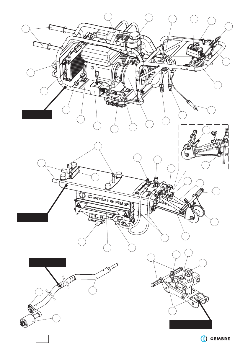
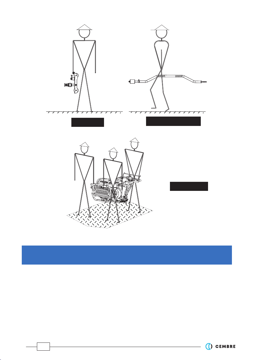
– Weight:
– complete machine:..................................................................................................................................117 kg
– pump unit:.................................................................................................................................................... 55 kg
– clamp unit:................................................................................................................................................... 48 kg
– carriage:...........................................................................................................................................................9 kg
– 3rd wheel bar: ................................................................................................................................................5 kg
– Combustion engine:
– type: .............................................................................................4-stroke, overhead valves, one cylinder
– model: ..................................................................................................................
Honda GX200 UT2-SMCR OH
– displacement:......................................................................................................................................... 196 cm3
– power:........................................................................................................................................... 4.3 kW 5.8 HP
– revs.:.......................................................................................................................................................3600 rpm
– fuel consumption:.............................................................................................. 1.7 litres/hour (3600 rpm)
– fuel: ...............................................................................................................unleaded regular grade petrol
– tank capacity:.........................................................................................................................................3.1 litres
– recommended oil:.....................................................................................................SAE 10W-30 (0.6 litres)
– clutch:........................................................................................centrifugal with automatic intervention
– start:....................................................................................................by rope pull with automatic rewind
– Hydraulic pump:
– max. pressure: ..........................................................................................................................................42 MPa
– oil supply: ............................................................................................................................... 5,6 litres/minute
– speed: ....................................................................................................................................................3600 rpm
– recommended oil:..............................................................................ARNICA-ISO32 or equivalents
– Acoustic noise (Directive 2006/42/EC, annexe 1, point 1.7.4.2 letter u)
– The continuous equivalent weighted level (A) of noise pressure
at the working place LpA is equal to..................................................85,2 dB (A), uncertainty KpA ± 4 dB
– The maximum value of instantaneous weighted noise pressure C
at the working place LpCPeak is......................................................................................................< 130 dB (C)
– The level of noise force produced
by the machine LWA is equal to.......................................................... 95,1 dB (A), uncertainty KWA ± 4 dB
–Risks due to vibration (Directive 2006/42/EC, annexe 1, point 2.2.1.1)
Tests carried out in compliance with the indications contained in ISO 5439 Standard, and under
operating conditions much more severe than those normally found, certify that the weighted
root mean square in frequency of the acceleration the upper limbs are exposed
is ahv = 3,57 m/sec2 uncertainty K ± 0,8 m/s2.
1.
GENERAL CHARACTERISTICS
(*) "Pandrol E clip" is a Pandrol Ltd trademark.

4
01 – TRANSPORT HANDLES
02 – LIFTING POINT IN NEUTRAL POSITION
03 – HYDRAULIC PUMP OIL TANK
04 – ACCELERATOR
05 – WORKLIGHT ON/OFF SWITCH
06 – STOP/EMERGENCY BUTTON
07 – CLAMP CONTROL LEVER
08 – HANDLEBAR
09 – QUICK RELEASE MALE AUTOMATIC HYDRAULIC COUPLER
10 – QUICK RELEASE FEMALE AUTOMATIC HYDRAULIC COUPLER
11 – HYDRAULIC PUMP
12 – PUMP UNIT FASTENING/RELEASE KNOB
13 – WORKLIGHT
14 – ELECTRICAL TERMINAL BOX
15 – ENGINE
16 – PUMP UNIT FASTENING/RELEASE KNOB
17 – OIL COOLING RADIATOR
18 – FRAME
19 – CLAMP UNIT LOCATING PINS
20 – TRANSPORT HANDLES
21 – PUMP UNIT LOCATING PINS
22 – QUICK RELEASE MALE AUTOMATIC HYDRAULIC COUPLER
23 – BRAKE RELEASE DEVICE LOCK
24 – QUICK RELEASE FEMALE AUTOMATIC HYDRAULIC COUPLER
25 – REAR HEIGHT ADJUSTMENT KNOB
26 – KNOB LOCK HANDLE
27 – WHEEL LOCK/RELEASE KNOB
28 – GAS SPRING RIGHT SIDE
29 – TRANSPORT HANDLE
30 – REAR WHEEL
31 – GAS SPRING LEFT SIDE
32 – FLEXIBLE HOSES
33 – INSERTING/EXTRACTING TOOTH
34 – HYDRAULIC RAM
35 – BRAKE RELEASE DEVICE
36 – YELLOW LOCATOR PLATE
37 – BAR
38 – SUPPORT WHEEL
39 – SUPPORT WHEEL ADJUSTMENT LEVER
40 – TRANSPORT HANDLES
41 – CONNECTING ROD FASTENING/RELEASE KNOB
42 – HORIZONTAL ALIGNMENT ADJUST KNOB
43 – CLAMP UNIT FASTENING/RELEASE KNOB
44 – FRONT CARRIAGE WHEELS
45 – BRAKE RELEASE HANDLE
2. MACHINE DESCRIPTION (Ref. to Fig. 1)

5
01
03 05 06
04
08
07
35
10
11
12
13
16
02
17
18
14
15
27
PUMP UNIT
CLAMP UNIT
19
20
21
22 24
28
29
30
32
34
36
33
26
25
31
09
45
FIG. 1 - MACHINE DESCRIPTION
23
38
37
39
3rd WHEEL BAR
CARRIAGE
44
40
43
42
41

6
To reduce overall dimensions and weight during transport, the machine is supplied disassem-
bled as four units.
It consists of four main sections which can be easily assembled/disassembled (Ref. Fig. 1):
–Pump unit: combustion engine/hydraulic pump for clamp operation.
–Clamp unit: for inserting and extracting E-clips.
–Carriage: for supporting and moving the machine along the track.
–3rd wheel bar: for stability and vertical positioning.
The machine is supplied complete with:
– 1pc spark plug key.
– 1litre hydraulic pump oil (do not use in engine).
– 1pc 12V - 21W spare worklight bulb.
3.1) Transporting the units
The four units are well balanced for easy transportation in accordance with the table and dia-
grams in Fig. 2. For uniform weight distribution and to transport the pump and Clamp units,
always use the transportation handles provided to lift the units.
3. UNPACKING THE MACHINE (Ref. to Fig. 1)
Distributed Load
per Person
(kg)
CLAMP UNIT
AB
A 24
B 24
C 9
D 5
E 15,5
F 15,5
G 24

7
.
C
F
E
D
3rd WHEEL BAR
FIG. 2 – TRANSPORTING THE UNITS
PUMP UNIT
CARRIAGE
4.1) Assembly/disassembly of the machine
Select the rail to be worked on and the direction of operation, then assemble the machine as
follows, referring to Fig. 4:
With pin (27) engaged and wheel (30) blocked, raise the clamp unit by means of the
handles (20 and 29) and rest this on the selected rail, positioning it between two sleepers.
Rest the support carriage on the track and then pull and turn the fastening/release
knob (43). Lift the clamp unit by means of the handle (20) and locate (19) pins fully into
their carriage housing as far as the stop.
Release the knob (43) to lock the clamp unit.
4. INSTRUCTIONS FOR USE (Ref. to Fig. 4)
2–
1–
G

8
Pull and turn the knob (41), insert the 3rd wheel bar in the carriage housing as far as the
stop, aligning the hole in the end of the rod with the pin knob.
Release the knob (41) and the wheel (38) which will act as a support on the opposite rail
so the assembly is stable and able to slide along the rail; the rod can be fitted in carriage
from either side for convenience in selecting the direction of work.
Pull and turn the knobs (12 and 16) at the base of the pump unit.
Lift the pump unit by means of the handles (01) and handlebar (08).
Rest the pump unit on the clamp unit and align the pins (21) with the relevant locating
holes on the under side of the pump unit.
Release the knobs (12 and 16) for locking.
Restore the oil delivery/return hydraulic circuit, connecting the flexible hoses by means
of the quick couplings (09 and 10) to the respective connectors (24 and 22) on the clamp
unit.
Connect the brake release device (35) (ref. to § 4.1.1)
3–
4–
5–
6–
4.1.1) Braking device (Ref. to Fig. 3a, 3b, 3c, 5)
The brake release device (35) must be connected in order to
run the machine along the rail:
– Introduce end part (A) into slot seat (B) located above the
rear wheel of the clamp unit (Ref. to Fig. 3a).
– Pullthe handle(C)upwards,releaseit in position than push
until is locked (Ref. to Fig. 3b and c).
– Pressthe handle (45) to verifythe correct engagement and
disengagement of release pin (P) from the wheel (Ref. to
Fig. 5 and 3c).
During the disassembly of the machine, before removal of
the pump unit, the brake release device must be disassem-
bled as follows:
– Pull the handle (C) and disconnect the end part (A) from
slot seat (B).
A
B
C
P
FIG. 3a
FIG. 3b FIG. 3c
35

9
DIRECTION OF
MOVEMENT
RAILS
41
38
43
20
21
16
01
09
10
08
24
22
29
30
12
19
21
3
5
4
1
FIG. 4 –
SEQUENCE OF ASSEMBLY
26
27
23
35

10
S
4.1.2) Disassembly of the machine (Ref. to Fig. 4 and 4a)
To disassemble the machine:
– First lower the rear part and lock with pin (27),
block wheel (30) then reverse the process de-
scribed in § 4.1.
– Before disconnecting the pump unit, make sure
to have disconnected the hydraulic circuit and
the braking device; locate the hoses in support
(S) got on the frame of the pump unit.
If necessary, with the machine fully assembled and
the motor switched off, the clamps can always be
opened or closed manually.
NOTE: Under normal conditions, the time taken to
remove the machine from the rail is approximately
60 seconds.
FIG. 4a – SUPPORT
4.2) Moving the machine (Ref. to Fig. 4b)
To move the machine along the track, the rear part must be raised to prevent the clamps knock-
ing against the E clip. To do this, simply:
1 -Pull and turn knob (27). The wheel arm will be freed.
2 -Slightly raise the machine by means of handlebar
(08); lifting will be made easier by the two gas
springs, then release the knob (27) to lock the
machine fully up.
3- Press brake release handle (45) against the
handlebar (08).
4- Push the machine along the rail.
FIG. 4b – MOVING THE MACHINE
08
2
3
45
4
27
1

11
4.3) Controls (Ref. to Fig. 5)
After gripping the handlebar (08), the operator can easily access all the unit controls and, more
specifically:
– Accelerator control lever (04): changes engine rpm.
– Worklight ON/OFF switch (05): in case of night work or bad lighting, the clamping area can
be illuminated by these side mounted lamps.
– Stop/emergency button (06) in a very visible position and easy to operate to stop the unit
normally and in case of an emergency.
NOTE: when this button is pressed it remains in OFF position. To start the engine, the button
should be turned clockwise so that it lifts automatically into the ON position.
The engine will not start unless the red button (06) is lifted.
– Clamp control lever (07) with swinging movement, for operating the clamps:
- right side for inserting E clips, "INSERT" position
- left side for extracting E clips, "EXTRACT" position
– Brake release lever (45): for safety reasons, the machine is equipped with an automatic
braking device. This device is always engaged within the rear wheel.
By pressing handle (45), the brake is released enabling movement of the machine along the
rail.
FIG. 5 – CONTROLS
EXTRACT
INSERT
05
07
06
04
45
08

12
33
– Loosen the handle (26).
– To raise the machine, turn the adjust-
ment knob (25) clockwise.
– To lower the machine, turn the ad-
justment knob (25) anticlockwise.
– After making adjustment, tighten
the handle (26) well.
25
26
FIG. 6
FIG. 7
˜3 - 4 mm
4.4) Setting the machine (Ref. to Fig. 6)
Before use, always check the height of the clamps with respect to the E clips.
Taking a retention plate as a reference point, check the position of the clamps with respect to
the plate itself.
In working condition, both clamps must be:
– Perfectly horizontal with respect to the rail.
– The insertion/extraction tooth (33) must be able to slide horizontally with 3-4 mm clearance
above the retention plate (see Fig. 6).
To adjust, proceed as follows:
4.4.1) Adjusting the rear height of the machine (Ref. to Fig. 7)
E clip retention plate

13
2
3
4
5
1
1
4.4.3) Adjusting the vertical alignment of the machine (Ref. to Fig. 9)
The distance of the teeth (33) from the retention plates of the E clips must be the same for both
clamps. If this is not the case, adjust support wheel (38):
– Loosen handle (39).
– Lower or raise the rod (37) to change the vertical angle of the machine and achieve correct
alignment.
– After adjustment, tighten the handle (39) well.
It may also be necessary to change the machine alignment on track bends.
FIG. 9
39
37
38
Note: It may be easier to use the knob (42) with the clamp unit partially disconnected from the
carriage by the knob (43).
FIG. 8
4.4.2) Adjusting the height of the front of the machine (Ref. to Fig. 8)
After making the adjustments described in § 4.4.1
proceed to adjust the machine horizontally
as follows:
0
1
2
3
4
5
43 42
– Line up the side of the machine so that the
clamp unit is parallel with the upper surface
of the railhead. If this is not the case, adjust
knob (42) on the carriage (Ref. to Fig. 8).
To lift the machine turn knob (42) anti-cloc-
wise. To lower the machine turn it clockwise.
The measuring scale will facilitate adjust-
ment by precisely defining the correct posi-
tion of the machine.

14
36
33
4.5) Operation
Before use, always check:
– Integrity of the machine.
– The correct coupling of the units making up the machine.
– Correct connection of the quick couplings and the braking device.
– Correct level of oil in pump.
– For any oil leaks in the hydraulic circuit (radiator, hoses, pump).
– Flexible hoses are in good condition and show no signs of wear or crushing.
– Protection devices in the clamp areas are firm and show no signs of damage.
– That the engine fuel tank cap is tight. Petrol is highly inflammable and can explode.
– Start the engine (see § 5).
– With knob (27) released, push the machine to the E clips points on which operations are to
be performed (see § 4.2).
4.5.1) Simultaneous insertion of 2 E clips (Ref. to Figs. 10 -11)
– Position the E clips in the retention plate eyelets, on both sides of the rail.
– Make sure the teeth (33) of the clamps are moved fully back by pulling the control lever to
the left "EXTRACT".
– Completely lower the machine, positioning the yellow locator plates (36) near the E clip
retention plates (see Fig. 11a)
E clips
FIG. 10
FIG. 11a E clip retention plate
Make sure the the locking knob (27) of the wheel is released (see § 4.2).

15
33
FIG. 11b
33
FIG. 11c
FIG. 11d
33
NOTE:
movement of one of the
clamps is schematically shown
in the illustrations; the other
will have an identical and op-
posite movement.
– Pull the control lever to the right in "INSERT" position to gradually move the teeth for-
wards with consequent insertion of both E clips (see Fig. 11b and 11c).
When performing the insertion operation, each clamp teeth (33) will move in opposite
directions.
NOTE: During clip insertion, the movement of the teeth may NOT be simultaneous because the two
clamps operate independently.
– After insertion, pull the control lever to "EXTRACT" position for teeth (33) reversal (see
Fig. 11d).
– Raise the machine and go onto the next E clips.
– Repeat the above operations.

16
4.5.2) Simultaneous extraction of 2 E clips (Ref. to Fig.12)
– Make sure the teeth (33) of the clamps are moved fully forwarded by pulling the control
lever to the right in "INSERT" position.
– Completely lower the machine, positioning the yellow locator plates (36) near the
E clip retention plates (see Fig. 12a).
– Pull the control lever (07) to the left in "EXTRACT" position: to gradually move the teeth
forwards with consequent extraction of both E clips (see Fig. 12b and 12c).
When performing the extraction operation, each clamps teeth (33) will move in opposite
directions.
33
36
FIG. 12a
FIG. 12b
FIG. 12c
E clip
retention plate
33
33
NOTE: During clips extraction, the movement of the teeth may NOT be simultaneous because the
two clamps operate independently.
Make sure the locking knob (27) of the wheel is released (see § 4.2).

17
– After removal, pull the control lever to "INSERT" position for forward movement of teeth
(33) (see fig. 12d).
– Raise the machine and go onto the next E clips.
– Repeat the above operations.
FIG. 12d
33
NOTE:
movement of one of the
clamps is schematically
shown in the illustrations;
the other will have an
identical and opposite
movement.

18
5. STARTING THE ENGINE
FIG. 13d
– Move the stop button (06) (see § 4.3) to "ON" posi-
tion (see Fig. 13a).
The engine will not start unless the red
button (06) is lifted.
– Move the fuel cock to "ON" position (see Fig. 13b).
– Move the air lever to "CLOSE" position (see Fig. 13b).
Do not use the air lever if the engine is hot and the
air temperature is high enough.
– Move the accelerator control lever (04) to mid stroke
(see Fig. 13c).
– Start the engine by pulling the starting cable until
a certain resistance is felt and then pull with force
(see Fig. 13d).
IMPORTANT: Do not allow the cable knob to return
forcefully and knock against the engine.
Return this slowly to its original position. This will
prevent damage to the starting device.
– As the engine heats up, gradually move the air lever
to "OPEN" position (see Fig. 13b)
– Move the accelerator control lever (04) fully forward
to achieve the correct rpm (see Fig. 13c).
–To stop the engine in emergency condition, press
button (06).
–To stop the engine in normal conditions:
move the accelerator control lever (04) fully back.
Press the button (06).
Move the fuel cock to "OFF".
Air lever
CLOSE
OPEN
Fuel cock
OFF
ON
Starting
cable knob
FIG. 13b
06
FIG. 13a
04
FIG. 13c

19
TROUBLESHOOTING
When the starting cable is pulled, the engine fails to start:
Is the Stop/Emergency button (06) released? (see § 4.3).
Is there enough oil in the combustion engine?
– The engine features an oil alert system to prevent damage caused by too little oil. Before
the level drops below safe limits, the alarm system automatically stops the engine.
Refer to the "HONDA owner’s manual" for the type of recommended oil and topping up.
THE HYDRAULIC OIL SUPPLIED WITH THE MACHINE IS INTENDED ONLY FOR USE IN THE
HYDRAULIC PUMP AND IS MUST NOT BE USED IN THE ENGINE.
Is the fuel stopcock open?
Is there fuel in the tank?
Is fuel reaching the carburettor?
– To check, loosen the carburettor drainage screw with fuel cock open and refer to the "HONDA
owner’s manual" .
Is the spark plug producing a spark?
– Removethe plug cap,clean aroundtheplugandremovetheplugusingthespannerprovided.
– Fit the plug back in the cap.
– Move button (06) to ON.
– After earthing the side electrode, pull the starting cable and check to see whether the plug
produces a spark.
If the engine still fails to start, contact CEMBRE (see § 7).

20
6. MAINTENANCE
6.1) Routine maintenance of the machine
At the end of each day, clean the machine carefully using a clean cloth, being careful to eliminate
all dirt or any oil stains, especially near the moving parts such as the clamp teeth and piston
rods and wheels. Do not rest the machine or units directly on dusty or muddy ground.
Regularly perform the following operations or inspections:
– Tighten all bolts.
– Check the integrity of the 3 rubber dampers which reduce vibration caused by the engine-
pump.
– Lubricate the clamp piston rods.
– If necessary change insertion/extraction teeth (33) and locator plates (36) as these become
damaged or worn by prolonged or improper use.
6.1.1) Maintenance of braking device (only for versions of machine with braked wheels)
The braking system is of robust construction and will require very little maintenance, however
the following routine checks should be performed.
Dust, sand and dirt are a danger for any mechanical device. Avoid putting the machine on
muddy ground. After every use, the machine must be wiped with a clean cloth, taking care to
remove any residue, especially around moving parts.
Rear Carriage wheel (A):
Before servicing or removing any parts of the machine, stop the engine and allow it to
cool. Always remove the spark plug cap from the spark plug when servicing the engine
to prevent accidental starting.
All electrical and mechanical maintenance shall only be carried out by authorised persons
in accordance with a safe system of work and CEMBRE instructions.
(A)
Table of contents
Other Cembre Industrial Equipment manuals